ECO-WORTHY L03US600WYTJ-1 600W All-In-One Solar Charge Inverter
Important Safety Information
- This manual contains important safety, installation, and operating instructions for the inverter.
- The following symbols are used throughout the manual.
- Warning: indicate a potentially dangerous condition. Use extreme caution when performing this task.
- Caution: indicate a critical procedure for the safe and proper operation of the inverter.
- Note: indicate a procedure or function that is important to the safe and proper operation of the inverter.
General Safety Information
- Installation and wiring must comply with the Local and National Electric Codes(NEC) and must be done by a certified technician.
- Read all of the instructions and caution in the manual before beginning the installation.
- There are no serviceable parts for this inverter.do not disassemble or attempt to repair the inverter.
- Make sure all connections going into and from the inverter are tight.
- There may be sparks when making connections, therefore, make sure there are no flammable materials or gases near the installation.
Inverter safety
- ALWAYS make sure inverter is OFF position and disconnect all AC and DC.
- Be careful when touching bare terminals of capacitors as they may retain high lethal voltage even after power is removed.
- Connecting when working on any circuit associated with the inverter-when connecting battery terminals,ensure the polarity of the battery connections is correct.Incorred polarity may cause permanent damage to the unit.
Battery Safety
- Do not let the positive(+)and negative(-)terminals of the battery touch each other.
- Use only sealed lead-acid,flooed,gel,or LiFePO4 batteries which must be deep cycle.
- Be careful when working with large lead acid batteries.Wear eye protec-tion and have fresh water avaiable in case there is contact with the battery acid.
- Over-charging and excessive gas precipitation may damage the battery plates and activate material shedding on them.Too high of an equalizing charge or too long of one may cause damage. Please carefully review the specific requirements of the battery used in the system.
Installation Safety
- The unit should be installed in a well-ventilated, cool, and dry envirment.-Make sure the fans of the unit and the ventilation holes are not blocked.-Do not expose the unit to rain, moisture, snow, or liquids of any type.
General Information
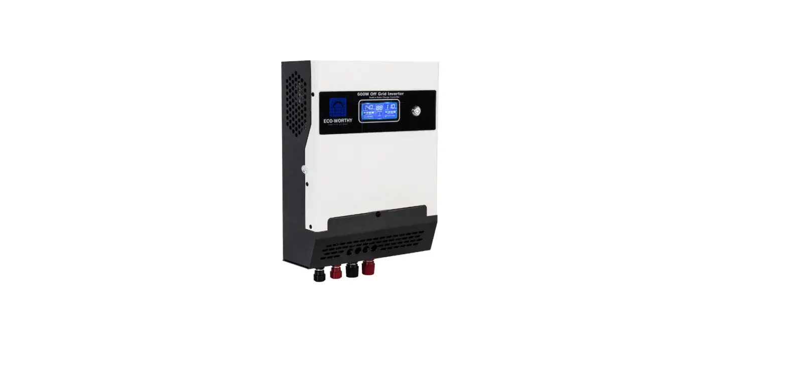
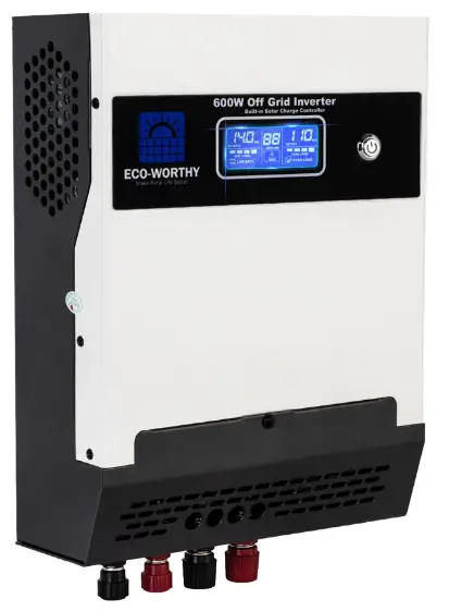
- The Eco-worthy ALL-IN-ONE Pure Sine Wave Charge Inverter delivers superior performance for Off-grid applications, a built-in solar charge controller for your solar panel kit.
Key feature
- Built-in PWM charge controller.
- SPWM pure sine wave output.
- Dynamic LCD displays and intelligent LEDs provide important system information.
- Manual ON/OFF switch controlling AC output.
- Adjustable fan, efficient heat dissipation, extending the life of the system.
- Supports lead-acid battery and lithium battery types.
- Solar protection: PV Short circuit protection, PV reverse protection, PV overvoltage protection.
- Battery protection: Undervoltage protection, overvoltage protection, overload protection, short circuit protection, overheat protection.


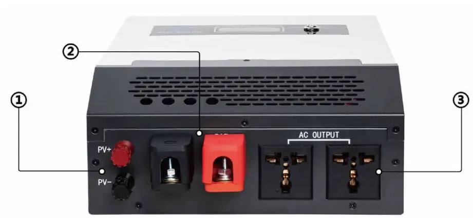
- Solar input terminal
- Battery terminal
- AC Outlets
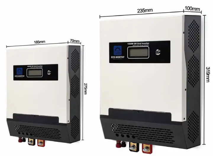
Dimensions
Installation
- Warning: Make sure the inverter is in the off position before connecting anything.
- Caution: Do not over-tighten the terminals. This could potentially damage the unit.
Location Recommendation
- Dry cool well-ventilated area
- Inverters must be in an area where the fans are not blocked or where they are not hit directly by the sun. They should be in an area free of any kind of moisture and allow for clearance of at least 10” around the unit to provide for adequate ventilation.
- Protection against fire hazard The unit should be away from any flam-mable material, liquids, or any other combustible material.
- Close proximity to battery bank Prevent excessive voltage drop by keeping the unit close to the battery bank and having a properly sized wire going from the battery bank to the inverter.
- Do not install the inverter in the same compartment as the battery bank because it could serve as a potential fire hazard.
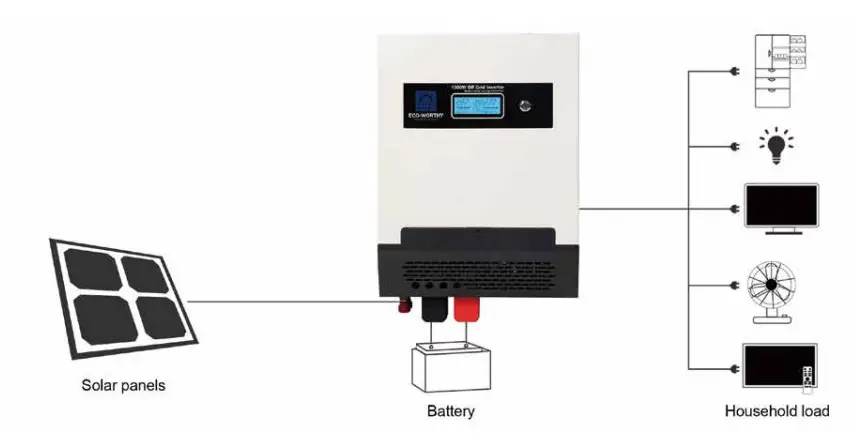
Wiring Step
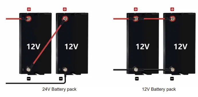
First confirm that the AC output switch is turned off, then connect the battery to the inverter, you need to distinguish 12V battery pack or 24V battery pack, then connect the solar panels to PV input of terminal of inverter, Be careful of the positive and negative poles. and turn on the inverter Switch at last.
Battery Wiring
Caution: e careful of the positive and negative poles. Reversing the poles may cause permanent damage to the inverter.
There may be a sparking occurring even the inverter is in the off posi-tion. To minimize sparking, it is recommended that the user have the appropriate size wire feeding into the solar inverters and/or install an external fuse leading into the inverter.
| Rated Battery- Discharge | Maximum battery charging | Recommended wiring | Recommended circuit breaker | Recommended ring terminal |
| 50A/62.5A | 25A/50A | 6mm2/10mm2 | 2P-63A/2P-120A | 8.2/8.2mmΦ |
- The solar inverter takes a 12V(600W) or 24V(1500W) battery input to operate.
- This will require combining 12V or 6V batteries in series to achieve the minimum voltage DC requirement.
- It is recommended to use battery cables with ring terminals.
- The ring terminals must be firmly tightened and secured on the respective battery terminals to prevent any excessive heating or resistance.

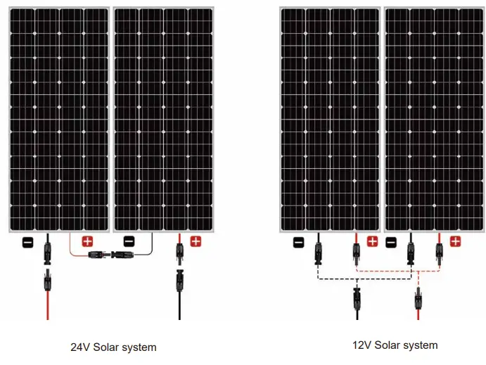
Solar Panel Wiring
| Maximum PV Charging Current | Recommended wiring | Recommended circuit breaker | Recommended wiring |
| 30A/50A | 4mm² | 4.3mm/4.3mmΦ | Bare wire |
- When combining panels in parallel it is recommended to use a combiner box for safety and organizational precautions.
- This will require combining solar panels in series or series-parallel to achieve the minimum voltage DC requirement.
- Caution: Connect the positive and negative PV wires to the respective positive and negative PV terminal blocks on the solar inverter.

Operation
- Assuming all connections are correct and tightly secured, Locate the power button on the solar inverter and press the power switch to the ON position. The following describes the basic operation of the solar invert-er charger.
LED Display Operation

- Solar input voltage
- Present battery capacity
- AC output voltage
- Load power
Maintenance
In order to maintain optimal long-term performance, it is recommended to perform inspections of the following items twice a year.
- Make sure that the air flow around the solar inverter is not blocked and remove any dirt or debris from the radiator.
- Check all terminals to see if there is corrosion, insulation damage, high temperature, or combustion/discoloration signs, and tighten the terminal screws.
Product specification
| Model | 600W 12V- 110V/230V (CSP600) | 1500W 24V-110V/230V (CSP1500) |
| Input Voltage | 12V | 24V |
| Rated Power | 600W | 1500W |
| Peak Power | 1200W | 3000W |
| Output Waveform | Pure Sine Wave | |
| Maximum PV Array Open Circuit Voltage | ||
| Maximum PV Array Wattage | 500W | 1200W |
| Maximum Solar Charge Current | 30A | 50A |
| Battery Voltage Range (BAT not included) | 10Vdc-15Vdc | 20Vdc-30Vdc |
| Solar Panel Input Voltage | 12V | 24V |
| Battery Charge Type (BAT not included) | PVM | |
| Protect Function | PV-Reverse Input Protection、PV-Short Circuit Protection、Over-Heating Protection、Over-Charge Protection | |
| AC Output Voltage | 120VAC±12V/230VAC ± 23V | |
| AC Output Frequency | 50Hz/60Hz | |
| Output Wave | Pure Sine Wave | |
| AC Output Sockets | 1 | 2 |
| Size | 275*185*74 | 319*235*100mm |
| Weight | 2.36Kg | 4.5Kg |
Troubleshooting
| Fault code | Fault Name | Description | Solution |
| 1 | Solar panels overvoltage | too many solar panels in series | reduce the number of solar panels in series |
| wrong solar panel | choose suitable panels | ||
| 2 | Generatrix overvoltage | DC-DC voltage increase system failed | repair |
| 4 | Generatrix undervoltage | DC-DC voltage increase system failed | repair |
| 8 | Overload | Overload | reduce the load power |
| 16 | Slightly overload | Slightly overload | reduce the load power |
| 32 | Battery undervoltage | Low battery power | charge your battery |
| Overdischarge recovery time | Restart | ||
| 64 | Battery overvoltage | Wrong battery type | choose right battery type |
| Overcharge recovery time | Restart | ||
| 28 | AC output undervoltage | DC-AC conversion failed | load removing and restart |
| 56 | Short circuit of AC output | Load short/Overload | load removing and restart |
| 12 | Over-temperature | long working time/Overload/ Cooling system | failed |
- E-mail: [email protected]
- Web: www.eco-worthy.com
- +44 20 7570 0328(EU)
- Tel: 1-866-939-8222(US)


