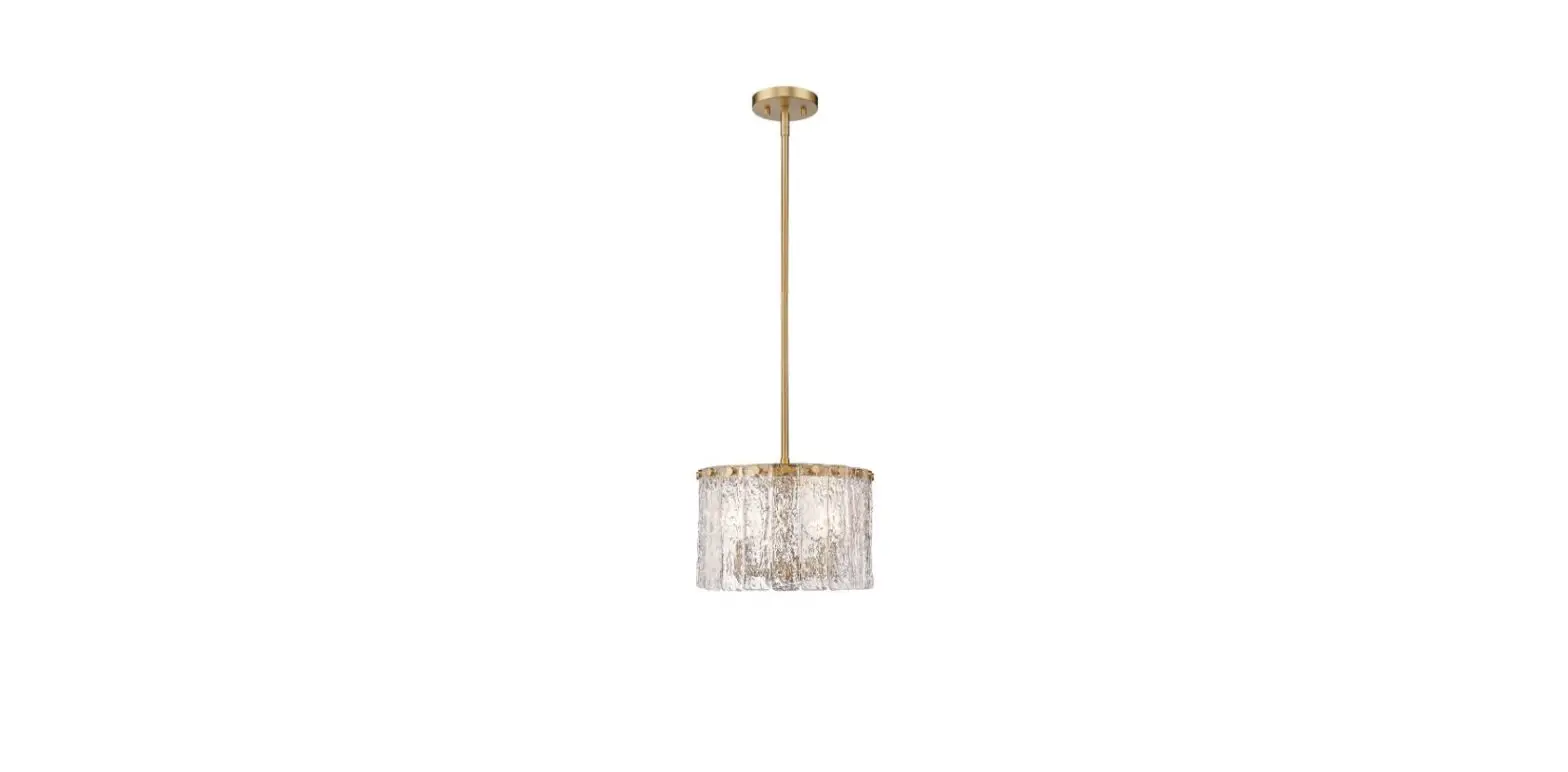
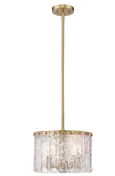
Z-Lite 1943P32-MGLD Glacier Pendant Chandelie
Product Information
- Product Name: Lamp Body
- Model Number: N/A
- Manufacturer: N/A
Product Usage Instructions
- Before starting the installation, ensure that the power is shut off at the fuse or circuit breaker.
- Consult the local electrical codes to understand the wiring and grounding requirements specific to your area.
- Follow the steps below for proper installation:
- Turn off the power at the circuit breaker box and remove the old fixture and all hardware from the Outlet Box. Unpack the new fixture carefully and lay out all the parts on a clear area. Take care not to lose any small parts required for installation.
- Thread the two Mounting Screws into the pre-drilled holes in the Mounting Plate, spacing them the same distance apart as the holes in the Canopy. Attach the Mounting Plate to the Outlet Box using the two Outlet Box Screws. Ensure that the side of the Mounting Plate marked GND is facing out.
- This lamp body consists of 8pcs Pipes that can be connected to achieve various heights. Measure and determine the correct number of Pipes required for your installation. Feed the wires and Safety Cable from the Lamp Holder through each Pipe, Frame, and Pipes. Connect the Pipe to the thread nipple from the Lamp Holder. Thread the thread nipple inside each Pipe and connect all the Pipes and Canopy together until secure. Feed the Safety Cable through the small holes in the side of the Column Nut and lock it securely with the screws.
- Take the lamp body assembly to the ceiling Outlet Box and connect the electrical wires. Note: When making wire connections, attach the fixture ground wire to the supply ground wire using a wire nut or attach them to the mounting plate with a green ground screw.
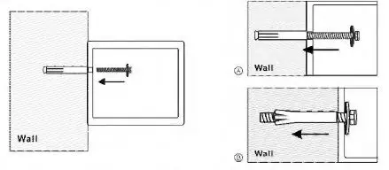
MOUNTING METHOD
- Fix the safe in the place which is not easy to move.
- Drill holes for expansion bolts (or clamping screws) in the right place.
- Turn the expansion bolts counterclockwise to separate.
- Use the expansion bolts (or clamping screws) to secure the case to the wall.
- Make sure the case is mounted in place as required and then tighten all screws. @ CAUTION: Use the expansion bolt when there is a concrete wall surface. Use the clamping screw when there is a wooden wall surface

For any help, kindly consult the local distributor
NOTICE ABOUT RECYCLING
‘Q” Your product is designed and manufactured with high-quality materials and components ~ which can be recycled and reused. This symbol means that electrical and electronic equipment, at their end-of-life, should be disposed of separately from your household waste. Please dispose of this equipment at your local community waste collection/ recycling center. In the European Union, there are separate collection systems for used electrical and electronic products. Please help us to conserve the environment we live in!
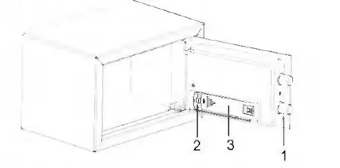
Schematic drawing of case
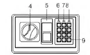
Schematic drawing of the control panel
- Bolts
- eset Button
- Battery Compartment
- Knob (Master Key)
- Emergency Lock Cover
- Green Light
- Red Light
- Yellow Light
- Confirming button
CAUTION: All drawings in this manual have been prepared based on the EA. The exterior design or component positions of other models may be different from what is indicated in the drawings, while the operation is the same.
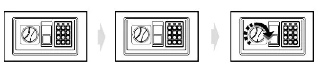
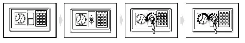
OPENING YOUR SAFE FOR THE FIRST TIME
- Upon first opening, users should open the safe with the emergency key. The operation in details refers to ·’opening the safe with the emergency key”.
- Remove emergency lock cover. then insert the emergency key, and turn it count clockwise.
- Turn the knob (master key) clockwise to open the door.
CAUTION: Finish operation, pull out the emergency key and keep ii in a safe place.
INSERTING THE BATTERIES
- Open the door.
- Insert 4 X 1.5V batteries into the battery compartment.
- Under normal condition, if both of the red and the green lights are on at the same time, it means the voltage is low and you should insert new batteries. 0 CAUTION: Replace 4 fresh batteries by lining them up in a manner as indicated by the “+ ” and ” – ” signs.When outage for longer than thirty minutes, you should reset the user’s code.
OPENING DOOR
- Input your user’s code (3 to 8 digits), each pressing results one buzzer beep and yellow light flashes.
- Press “A” (C /#)or “B” (E /*)button, the green light will be on.
- Rotate the knob (master key) clockwise and pull outwards within 5 seconds, the door is opened.
0 CAUTION: The user preset code “159··. Please input the user code again if the yellow light flashes with three buzzer beeps.
AUTOMATIC LOCK
- 3 continuously wrong entries will activate the warming beep for 20 seconds. 0 CAUTION:The key pad would be disabled during the beeping. You can only stop the beeps by opening the safe with emergency key and power-cut by removing the battery.
SETTING THE USER CODE
- With the door open, press the reset button one, and start setting the code when the yellow lights goes on.
- Input new code (3-8 digits), and press the “A” (CI#) or “B” (E /*)button to confirm with 2 buzzer beeps, which indicates the acceptance and storage of the new code.
- If the yellow light flashes with 3 buzzer beeps, which means the code changing is not effective, and you need to try again.
SETTING MASTER CODE
- Open the safe, input “O” twice and press the reset button, start setting the code when the yellow light goes on.
- Input the new master code (3-8 digits), then press the “A” (CI#) or “B” (E /*) button to confirm, it will be confirmed by 2 beeps and the yellow light flashes two times, then setting is done successfully.
- If the yellow light flashes three times, it means the new code is invalid and should operate again.
OPENING THE SAFE WITH THE EMERGENCY KEY
Upon first receipt of the safe, or either the electronic circuit malfunction or codes unknown. You could also use the emergency key to open the safe.
- Remove the cover of the emergency lock.
- Insert the emergency key, turn it count clockwise, then turn the knob (master key) clockwise to open the door.