
CANBAT CLI120-48 Lithium Iron Phosphate Battery LiFePO4
 SAFETY INFORMATION
 SAFETY INFORMATION
It is essential to read, understand, and follow these instructions prior to installing or operating Canbat batteries.
Warning
- Failure to follow the instructions in this manual may result in serious injury or death.
- Do not place or install near flammable or explosive materials.
- Install the battery module out of the reach of children and animals.
- The CLI120-48 is over 75 kg (165 lb). Lift with multiple people and use lifting equipment rated to lift and support at least 200 lb.
- Do not dispose of this product with household waste.
Caution
Risk of electric shock.
Attention
Disconnect the battery before carrying out maintenance or cleaning. Read this manual before installing and operating the battery.
Note
Make notes if needed during the installation process. This is particularly helpful if the installation is conducted over multiple days.
Recyclable
Please contact your local solid waste recycling agency for recycling instructions.
- The battery is to be installed on fire-retardant objects. Do not place flammable materials inside or near the battery.
- Do not leave paper, metal crumbs, tools and/or other foreign bodies inside the battery module.
- In non-emergency cases, the operation and stop of the monitoring system shall not be controlled by means of connecting and disconnecting the input power.
- There are no user-serviceable parts inside of the CLI120-48. Do not attempt to disassemble the battery module. Opening the module case is dangerous and voids the warranty. Simply keep the exterior clean, dry, and dust-free.
- Please pay attention to the screen-related reminders when the system is performing electrical debugging.
- A small risk of spark does exist while making connections. Ensure the area is free of explosive gasses and liquids. Also, ensure the battery is not installed in a confined environment. This includes flammable fuel-powered machinery, holding tanks, pipe fittings, and connectors.
- High voltage battery connections (configurations of greater than 36V DC nominal) can be dangerous in any DC system. The CLI120-48 is a 48V nominal battery system and is greater than 36V DC at the terminals when charged! DC voltages over 52V can stop the human adult heart; please be careful and wear insulated gloves.
- NEVER reverse the polarity (positive and negative) of your unit’s connections. NEVER short circuit your CLI120-48.
- The CLI120-48 is for 48V systems only. NEVER connect the battery modules units in series! This is unsafe and will void the warranty.
PRODUCT INTRODUCTION
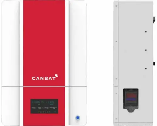
- Canbat CLI120-48 is a wall-mount energy storage system that provides a 6.144 Kilowatt-hour battery in a single package. Up to 14 units can be connected in parallel for additional capacity. The battery does not support series connections. Attempting series connections is dangerous and voids the warranty. The CLI120-48 has been designed for trouble-free mounting and is easy to connect with other system components. Supported inverters are Sol-Ark, Victron and Schneider Electeic.
The battery utilizes advanced lithium iron phosphate (LiFePO4) technology with a unique built-in BMS (Battery Management system). It is compact, efficient, light weight, safe and eco-friendly. - BMS Features
- Charge/discharge management
- Thermal management
- Communication management
- Cell balance management
- Data management and remote monitoring
- Remote management and maintenance
PRODUCT SPECIFICATION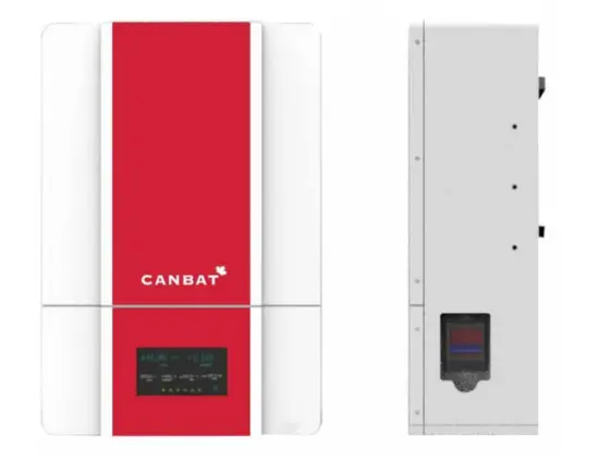
Model Number: CLI120-48
BATTERY SPECIFICATION
| Item | Specification |
| Battery Type | LiFePO4 |
| Nominal Voltage | 51.2V |
| Nominal Capacity | 120Ah |
| Nominal Energy | 6.144kWh |
| Standard Charge Voltage | 56.0V |
| Recommended Floating Charge Voltage | 54.4V |
| Maximum Continuous Charge Current | 120A |
| Maximum Continuous Discharge Current | 120A |
| Peak Discharge Current (3s) | 300A |
| Maximum Continuous Discharge Power | 5kW |
| Peak Discharge Power (3s) | 15kW |
| Approx Weight | 75 Kg (165 lbs) |
STRUCTURE SIZE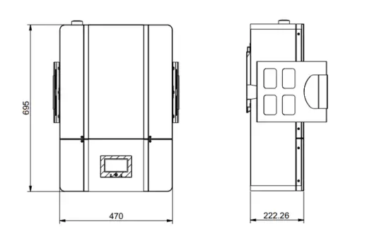
STORAGE AND TRANSPORT
STORAGE
The CLI120-48 LiFePO4 battery must be stored as follows:
This battery should be stored indoors in a dry, clean, shaded, and well-ventilated area at a temperature between 15° and 35°C (59° and 95°F). The battery needs to be charged to at least 70% before storage. Store the battery modules for no longer than 6 months. If storage exceeds 6 months, cycle the battery at least once.
- Over-discharge will damage the battery and void the warranty. The battery must be charged within a maximum of 10 days after the over-discharge stage has been reached.
- The battery must not be dropped, installed on its side or face any serious impact.
- Ensure the battery is stored out of reach of children and pets.
TRANSPORT
- The battery module should be kept horizontal while being moved, except when it is being lifted into place for mounting.
- Two or more people are required to lift/move the battery.
- Do not drop the battery module or damage will occur.
- If you are transporting the battery while it is still in the packing crate, do not stack them more than two layers high and ensure they are strapped together to prevent tumbling.
- Only transport the CLI120-48 battery module facing up.
INSTALLATION PREPARATION
CHECK THE PACKING LIST
| Parts | Quantity |
| Modules communication cable_RJ45+RJ45_150mm | 1 unit |
| Terminal matching resistance_120Ω_RJ45 | 1 unit |
| Wall mounting bracket | 1 unit |
| Lift handle | 2 units |
| Expanding screw M8*60 | 8 units |
PRODUCT IMAGE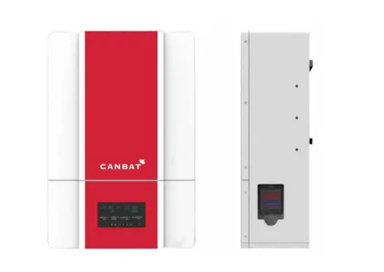
BATTERY INSTALLATION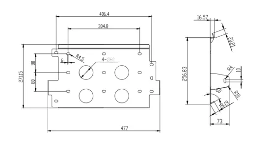
INSTALLATION LOCATION
ENVIRONMENT REQUIREMENT
| Application Scenarios | Residence |
| Operating Environment | Indoor and place away from strong electromagnetic radiation |
| Discharge Temperature | -20~55 |
| IP Grade | IP55 |
| Storage Temperature | Short-term (≤ 1month): -20~45°C (-4~113°F) Long-term (≥ 1month): 15~35°C (59~95°F) |
| Operating Humidity | 0 ~ 85% |
| Max Charge/Discharge Current Vs. Altitude | 100A @ ≤ 2,000m 90A @ 2,000m~4,000m |
| Case Ground Requirement | Use at least 2mm² copper wire with a resister ≤1Ω. |
SITE SELECTION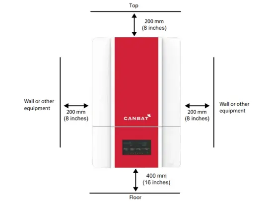
The total weight of the CLI120-48 battery is about 75 kg (165 lbs). Please ensure that the wall or bearing wall studs are strong enough to withstand such weight. Mounting brackets are included with the battery. The site’s absolute maximum altitude is 9843 feet (3000 m). To operate the CLI120-48 at 3000m, limit the output power to max 90A or about 5KW. To ensure the battery is well-ventilated, ensure there is sufficient space from all sides as follows:
- Top: 200mm (8 inches)
- Right: 200mm (8 inches)
- Left: 200mm (8 inches)
- Bottom: 400mm (16 inches)
ATTENTION
The battery system must be installed and ventilated in a cool and dry place. Ensure the battery is away from any heat source and avoid sunlight to prevent the battery from cutting off the power output or entering system failure mode due to overtemperature. Keep the battery away from transformers and other equipment that cause a strong electro-magnetic field environment, as such can disturb communication and power supply. Keep away from fire; keep away from flammable and explosive items. Keep away from children and pets. The battery must only be installed by a professional. The battery should be in a heated environment. The battery has cold-temperature protection and will not recharge if the temperature is below 0°C (32°F). If the battery is already charged, it can discharge in temperatures as cold as -20°C (-4°F).
WALL MOUNTING BRACKET INSTALLATION
If you are anchoring the mounting plate into wood studs use at least four (one at each corner) #14 (1/4”) wood screws with washers. The screws must be long enough to penetrate at least 1½” into the studs.
If you are anchoring into plywood wall material, the plywood must be at least ¾ inch thick. Usea four (one at each corner) #14 (1/4”) wood screws with washers. The screws must be long enough to penetrate at least ¼ inch beyond the back of the plywood. You can also use four (one at each corner) heavy-duty ¼-inch toggle bolts, rated for at least 250 lb.
If you are anchoring into metal studs, the studs must be a minimum of 18 gauge. Use at least four (one at each corner) #14 sheet metal screws with washers. The screws must be long enough to penetrate at least three threads beyond the stud. If installing on a wall with metal studs less than 18 gauge, a mounting surface (such as a larger plywood surface to distribute the weight) must be attached to the wall prior to installing the CLI120-48.
If you are anchoring into concrete or masonry, the minimum strength of the concrete must be at least 2500 PSI, while the minimum strength of the masonry must be at least 1500 PSI. Drill holes into the concrete or masonry with the 12 mm drill bit at the marks you made earlier. Hammer the included M8*30 expansion screws into the wall. Attach the plate onto the wall with the M8 bolts.
 CABLE CONNECTION
TOOLS & MATERIALS
The following tools and materials are required:
- Positive and negative battery cables. Recommend copper cables (AWG2).
- Positive and negative Terminal lugs. Recommended: M10 (diameter: 10mm).
- Recommended conduit size: PG36 (for power bus) & PG21 (for com Bus).
- Screwdriver • RJ45 cable • CCOHS approved personal protective equipment.
CONNECTING ORDER
Below is a summary of how the battery module to be connected. More
| Process No. | Operation |
| 1 | Set the module communication address by the DIP Switch. (Refer to page 16) |
| 2 | Connect the Module COM cable (RJ45 connector) between battery modules. |
| 3 | Connect the inverter COM Cable between the battery and the inverter. |
| 4 | Connect the battery Power Cable to the Bus-wire |
| 5 | Connect the Bus-wire to the inverter. |
| 6 | Close the inverter breaker and each battery pack’s DC breaker |
| 7 | Press each module’s button till the RUN LED flashes to power on the modules |
| 8 | Start charge or discharge. |
- When assembling, please follow the process above in order.
- When disconnecting the battery from the system, please follow the steps in reverse order to avoid the battery displaying an error.
- The battery module’s positive and negative leads must not be reversed or short-circuited. Doing so is dangerous. Short circuits are automatically registered in the BMS memory and the warranty will be void.
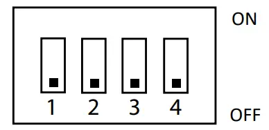
SET THE ADDRESS OF THE DIP SWITCH
The DIP switch helps multiple battery modules connected in parallel communicate with each other. If you are only installing a single battery, leave the switch off as default. If you’re connecting multiple batteries for a larger battery bank, please configure the DIP switch as follows:
| Module number | DIP Switch | |||
| #1 | #2 | #3 | #4 | |
| Single module | OFF | OFF | OFF | OFF |
| 1st Master module | ON | OFF | OFF | OFF |
| 2nd Slave module | OFF | ON | OFF | OFF |
| 3rd Slave module | ON | ON | OFF | OFF |
| 4th Slave module | OFF | OFF | ON | OFF |
| 5th Slave module | ON | OFF | ON | OFF |
| 6th Slave module | OFF | ON | ON | OFF |
| 7th Slave module | ON | ON | ON | OFF |
| 8th Slave module | OFF | OFF | OFF | ON |
| 9th Slave module | ON | OFF | OFF | ON |
| 10th Slave module | OFF | ON | OFF | ON |
| 11th Slave module | ON | ON | OFF | ON |
| 12th Slave module | OFF | OFF | ON | ON |
| 13th Slave module | ON | OFF | ON | ON |
| 14th Slave module | OFF | ON | ON | ON |
CAN & COMMUNICATION PORT PIN DEFINITION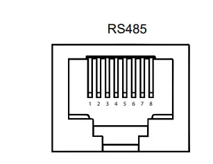
| Pin No. | Definition |
| 1 | Inverter RS485B |
| 2 | Inverter RS485A |
| 3 | NC |
| 4 | NC |
| 5 | NC |
| 6 | NC |
| 7 | BMS debug RS485A |
| 8 | BMS debug RS485B |
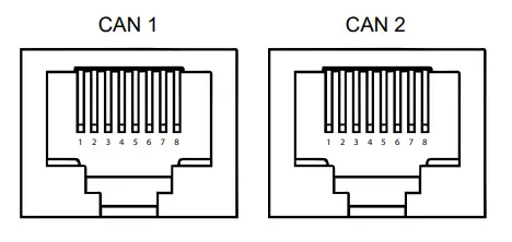
| Pin No. | Definition |
| 1 | NC |
| 2 | NC |
| 3 | CANL |
| 4 | CANL |
| 5 | CANH |
| 6 | CANH |
| 7 | NC |
| 8 | NC |
COMMISSIONING
OPERATION
- Start-up: Close the inverter’s main DC breaker → close the DC breaker of the battery → hold the power button till the RUN led flash (at least 2s) → wait for 5s for the pre-charge function → turn on the inverter.
- Running: If the start-up has been completed successfully, the green RUN button will be turned on in a solid state. The battery will have an output. If the screen turns off due to energy-saving mode, press the power button once and the screen will turn back on for 1 minute.
- Alarm*: If the battery enters protection mode or if there are any warnings, the LCD screen will turn ON, and the red ALM LED will turn on as well. ALM is short for Alarm. See the below table for alarm functions.
- Turn-Off: To turn off the battery, hold the power button for 3 seconds until the LCD screen turns off. Once the battery is off, it will not have an output.
| Items | Description | |
|
Overcharge | Over-charge alarm for each cell | 3.60±0.03V (Not displayed on LCD or alarm LED) |
| Over-charge protection for each cell | 3.75±0.03V, Delay time:1s (Not displayed on LCD or alarm LED) | |
| Over-charge release for each cell | 3.40±0.03V | |
| Over-charge alarm for total voltage | 57.2V±0.5V | |
| Over-charge protection for total voltage | 58.4V±0.5V for 1±0.5s | |
| Over-charge release for total voltage | 56V±0.5V | |
| Over-charge release method | Under the release voltage | |
| Over | Over-discharge alarm for each cell | 2.90±0.03V |
| discharge | Over-discharge protection for each cell | 2.70±0.03V for 1±0.5s |
| Over-discharge release for each cell | 3.00±0.03V | |
| Over-discharge alarm for total voltage | 46.4V±0.5V | |
| Over-discharge protection for total voltage | 43.2V±0.5V for 1±0.5s | |
| Over-discharge release for total voltage | 48V±0.5V | |
| Over-discharge release method | Charge to recovery | |
|
Overcurrent | Charge over-current alarm | 135±5A |
| Charge over current protection | 150±5A for 5±1s | |
| Charge overcurrent release method | Auto release after 1min | |
| Discharge over-current alarm | 135±5A | |
| Discharge over current protection | 150±5A for 5±1s | |
| Overcurrent release method | Auto release after 1min | |
|
Over-temperature | Charge over temperature alarm | 50±3℃ |
| Charge over-temperature protection | 55±3℃ | |
| Charge over-temperature release | 45±3℃ | |
| Discharge over temperature alarm | 60±3℃ | |
| Discharge over-temperature protection | 65±3℃ | |
| Discharge over-temperature release | 55±3℃ | |
|
Under Temperature | Charge under temperature alarm | 3±3℃ |
| Charge under temperature protection | 0±3℃ | |
| Charge under temperature release | 5±3℃ | |
| Discharge under temperature alarm | -15±3℃ | |
| Discharge under temperature protection | -20±3℃ | |
| Discharge under temperature release | -10±3℃ | |
| SOC | LOW SOC Alarm: 10% | |
BATTERY INFORMATION DISPLAY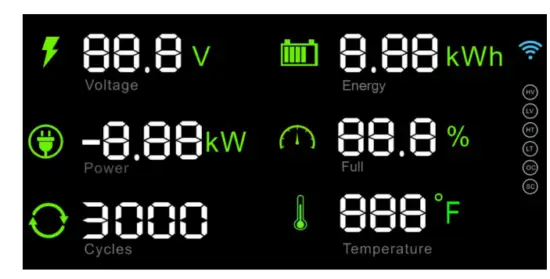
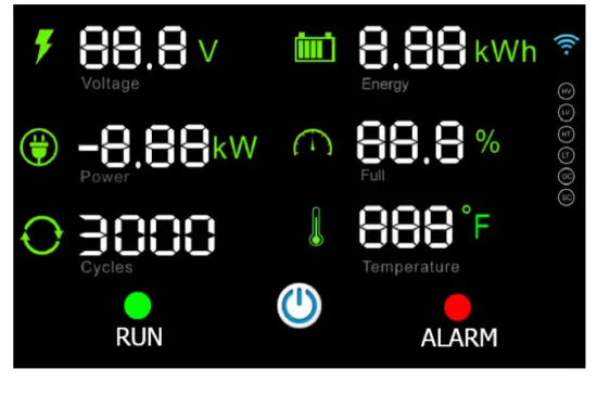
LCD CONTROL PANEL
The control panel displays a variety of useful information regarding the operation of your system, such the voltage, state of charge and temperature.
SUPPLEMENTARY INSTRUCTIONS
| Display | Indicator | Note |
| Battery voltage | ||
| Residual energy | ||
| Current power | Negative value indicates discharging. Positive value indicates charging. | |
| SOC | State of Charge | |
| Cycle Number | ||
| Battery temperature | ||
|
| WIFI mark | Off = Not connected to Wifi.
Rolling = Battery attempting to connect to Wifi. Flashing = The battery is in pairing mode and can be connected to Wifi.On Steady = Connected to Wi-Fi sucessfully. Number of semi circles (1 to 3) indicates the Wi-Fi signal strength. |
| HV | The battery will light these indicators when a warning or alarm condition occurs:
HV = Battery High Voltage LV = Battery Low Voltage HT = Battery High Temperature LT = Battery Low Temperature OC = Charge or Discharge Over Current SC = Short Circuit | |
| LV | ||
| HT | Alarm signals | |
| LT | ||
| OC | ||
| SC |

MAINTENANCE
TROUBLESHOOTING REFERRING ERROR SIGNAL
When the battery is operated beyond the prescribed range, it goes into fault state by turning on the red LED “ALARM”. User can check the status from the LCD screen of battery to determine the current state the battery.
The possible error signals areas follows:
| Error signal | Troubleshooting | |
| Battery High-Voltage HV | Reduce charging voltage or stop charging. | |
| Battery Low-voltage LV | Stop discharging and charge the battery within 10 days. | |
| Battery High-temperature | HT | Stop charging or discharging until battery temperature falls below the recover temperature. Refer to BMS alarm & protection parameters on 10. |
| Battery Low-temperature | LT | Stop charging or discharging until battery temperature rise above the recover temperature. Refer to BMS alarm & protection parameter. |
| Battery charge/discharge Over-Current | OC | Reduce the charging current or discharging power, and battery will auto release in 1minutes. |
| Battery Short-Circuit | SC | Check the external power wire of the battery, eliminate short-circuit connection, and then restart the battery. |
TROUBLESHOOTING UNDER OTHER SITUATIONS
If all above alarm signals are OFF and the “RUN” green LED is on, but the user still faces issues, please troubleshoot as follows:
| Description | Troubleshooting |
| Battery module cannot start the inverter | 1. Check power and communication cables to the inverter. 2. Contact the inverter manufacturer. |
| Battery unable to charge by the inverter/charger. | 1. Check power and communication cables to the inverter/inverter. 2.Check inverter specification to make sure its charge voltage is suitable for this type of battery referring “2.2 Battery Specifications” |
|
When battery modules are connected in parallel and one of them has no output. | Check this module’s voltage and current on LCD screen. If the voltage difference among the packs is more than 2V and there is a certain current, it means this module is equalizing. This process takes several minutes to hours, please wait patiently. If not, please check next: 1.Check the DIP switch and ensure its configured properly. |
Note: If the problem is still not resolved after troubleshooting, please contact the manufacturer below.
Contact Information
CANBAT TECHNOLOGIES INC.
Address: 1285 W Broadway #600 Vancouver, BC V6H 3X8
Web: www.canbat.com
Tel: +1 778-358-3925
Email: [email protected]


