Azoteq AZBAT48100C Lithium-Iron Phosphate Battery
This product manual provides further detail on the AZBAT48100C LiFePO4 battery. Please familiarise yourself with the operating instructions in this document before operating the battery.
Revision History
| Version | Release date | Change Notes |
| 1.00 | 06 June 2022 | Creation |
| 1.04 | 29 August 2022 | Released |
Disclaimer
This product manual provides further detail on the AZBAT48100C LiFePO4 battery. Please read the operating instructions in this document before using the battery. The installation should adhere to local regulatory guidelines and standards. Also familiarise yourself with the warranty conditions of this product to ensure it is operated within stipulated requirements. Please complete the battery registration from the Azoteq website to activate your warranty. (https://www.azoteq.com/warranty/) Please refer to the disclaimer at the end of this product manual for further information.
Overview
The AZBAT48100C incorporates 30x 3.2V (15S2P configuration); 52Ah Lithium-Iron Phosphate (LiFePO4) cells with a recommended 0.3C charge and 0.5C discharge current rating. The battery incorporates a battery management system (BMS) which provides the following functionality:
- Protection
- Total Overvoltage
- Cell over- and undervoltage
- Charge and Discharge overcurrent
- Short circuit
- Over and under temperature
- Control
- Charge and discharge
- Cell balancing
- Sleep function
- Alarm and warning dry contacts
- Communication
- CANBUS and MODBUS communication ports to interface with the inverter.
- Parallel MODBUS for parallel connections between batteries as well as battery monitoring.
- RS232 communication for firmware updates and battery monitoring.
The BMS has been tested with leading inverters, including SunSynk, Deye, Voltronic, Victron and GoodWe and has been IEC 62619 certified.
Safety Precautions
The AZBAT48100C Lithium Ion battery operates at hazardous low DC voltage, please be aware of potential arc and shock hazards and handle with caution. Please make use of a qualified installer and have them familiarize themselves with this product manual. Failure to do so or to disregard any of the instructions or warnings in this document can result in electrical shock, serious injury, or death and might damage battery, potentially rendering it inoperable. Please follow the following safety precautions when dealing with the battery:
- Do not operate the battery in temperatures outside the range of 0°C to 45°C.
- Do not open the battery, disassemble, or attempt to repair it as this will void the warranty.
- Do not remove or tamper with the QC sticker or any other labels on the battery as this will void the warranty.
- Do not connect the battery terminals directly to PV wiring.
- Do not connect multiple batteries in series.
- Do not use different battery makes, models or manufacturers in parallel or series.
- DO NOT mix Azoteq Battery models (AZBAT A, B or C)
- In the event of a fire, DO NOT use water to extinguish the fire.
- Take precaution to prevent the battery terminals shorting due to unforeseen events.
- The batteries should not be subjected to mechanical shock or vibration.
- Batteries should be recharged within 12 hours after being fully discharged.
- The supplier does not take any responsibility for direct or indirect damages caused by incorrect use or negligence. Please refer to the terms and conditions of sale and the warranty document.
Product Information
Production dimensions
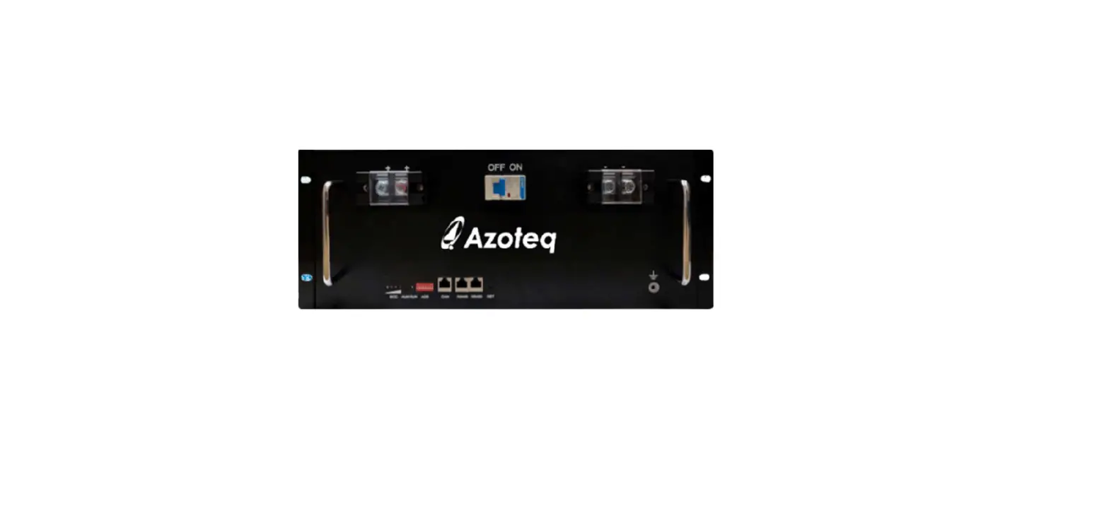
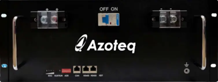
The battery is mounted in a durable 4U steel casing and fits in a standard 19-inch rack. The battery has two double M8 terminal connections on the front for a sturdy connection to the battery cables.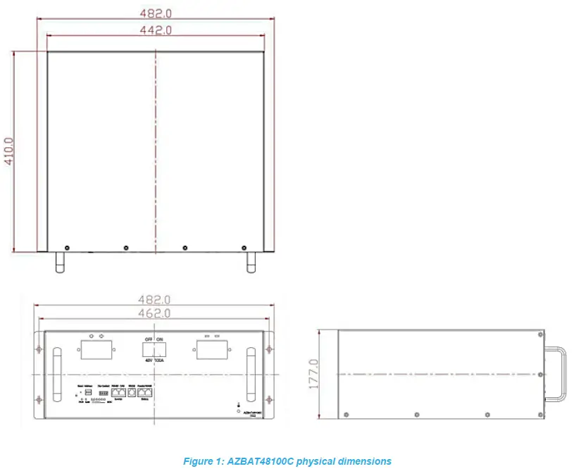
Detailed Parameters
AZBAT48100C electrical and environmental parameters
|
GENERAL | Model | AZBAT48100C | |
| Battery Type | LiFePO4 | ||
| Nominal Voltage | 48V | ||
| Nominal Current | 100Ah | ||
| Nominal Capacity | 4.8kW | ||
| Cycle life @ 80% DoD* | 5 000 | @ 25°C | |
| Cycle life @ 100% DoD* | 2 000 | @ 25°C | |
| Recommended DoD | 80% | ||
| Operating Temperature | 0-45°C | ||
| Dimensions [mm] | 482(W) x 410(L) x 177(H) | ||
| Weight | 48kg | ||
| IP Rating | 20 | ||
| Certification | IEC 62619 | ||
| UN 38.3 | |||
| Storage conditions | -25°C to 60°C (less than 6 months) 0°C to 25°C (12 months) | 25-85% relative humidity | |
|
CHARGE AND DISCHARGE | Charge Voltage | 54V | |
| Float / Sustain Voltage | 53V | ||
| Recommended Charge | 33A (0.33C) | ||
| Maximum Charge | 50A (0.5C) | BMS protection for higher charge current | |
| Recommended discharge | 50A (0.5C) | ||
| Maximum Discharge | 95A (0.95C) | ||
|
BMS | Communication interface | CANBUS, MODBUS and RS232 | |
| Parallel | Up to 15 batteries | ||
| Protection – short | Short circuit current | 600A | |
| Short circuit protection delay | 300µs | ||
| Short circuit recovery condition | Automatic | ||
| Protection – voltage | Low voltage alarm | 42.0V | |
| Low voltage shutdown | 40.5V | ||
| Low voltage release/restart | 44.25V | ||
| SoC low alarm | 10% | ||
| Over voltage alarm | 54.0V | ||
| Over voltage protection | 54.8V | ||
| Over voltage release | 50.7V | ||
| Protection – charge | Over charge current alarm | 60A | |
| Overcharge cut-off current | 65A | ||
| Overcharge cut-off current delay | 1s | ||
| Protection – discharge | Over-discharge current alarm | 105A | |
| Over discharge cut-off current | 110A |
| Over discharge cut-off current delay | 1s | ||
| Over discharge recovery condition | Automatic (1 min) | ||
| Over discharge cut-off current | 150A | ||
| Over discharge cut-off current delay | 100ms | ||
| Over discharge recovery condition | Automatic (1 min) | ||
| Protection – temperature | Charging over temperature alarm | 60°C | |
| Charging over temperature | 65°C | ||
| Recovery of overcharge temperature | 55°C | ||
| Charging under temperature alarm | 0°C | ||
| Charging under temperature | -5°C | ||
| Charge under temperature recovery | 0°C | ||
| Discharge over temperature alarm | 65°C | ||
| Discharge over temperature | 70°C | ||
| Discharge over temperature recovery | 60°C | ||
| Discharge under temperature alarm | -15°C | ||
| Discharge under temperature | -20°C | ||
| Discharge under temperature recovery | -15°C | ||
| Environmental over temperature alarm | 65°C | ||
| Environmental over temperature protection | 70°C | ||
| Environmental temperature recovery | 65°C | ||
| Environmental under temperature alarm | -15°C | ||
| Environmental under temperature | -20°C | ||
| Environmental under temperature recovery | -15°C | ||
| Balance | Voltage | >3.4V Voltage difference >30mV | |
| Sleep | Cell voltage | 3.15V | |
| Delay | 5 min | ||
| SWITCH | Breaker model | DC125A |
- Cycle Life is defined as the number of cycles specified until the battery has less than 80% of the initial capacity.
Battery interface
This section details the front panel interface of the battery.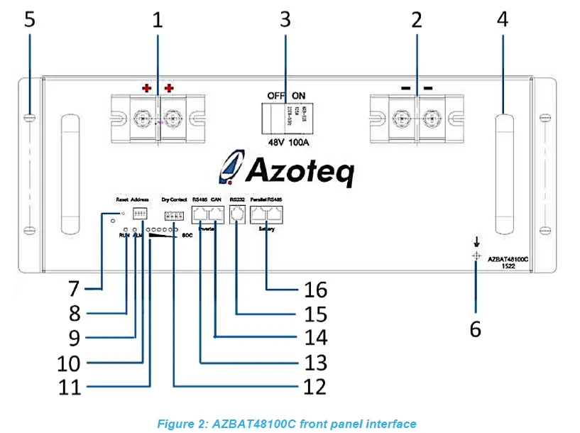
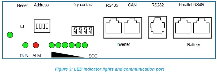
Table 2 describes the front panel functional interface as shown in figure 2
Table 2: AZBAT48100C Interface description
| Index | Interface | Description |
| 1 | Positive battery terminals | The battery has two positive M8 terminals. The one terminal can be used to connect to the inverter while the other terminal can be used to connect to a parallel battery. |
| 2 | Negative battery terminals | The battery has two negative M8 terminals. |
| 3 | Breaker switch | Switches power to the battery terminals ON and OFF. |
| 4 | Handle | Handle for lifting and moving the battery. |
| 5 | Mounting hole | 4x holes located on the front sides of the battery for mounting to a 19-inch rack. |
| 6 | Earth connection | Use this to connect the battery to EARTH as per local wiring regulations. |
|
7 |
Reset | Switches the battery management system (BMS) ON and OFF. The BMS needs to be turned on initially. Please refer to Table 3 for the LED indicator definitions.
|
| 8 | RUN LED | Please refer to Table 3 for a detailed overview for these indication lights. (Green) |
| 9 | ALARM LED | Please refer to Table 3 for a detailed overview for these indication lights. (Red) |
|
10 |
Address | Used to set the battery address when the batteries are used in parallel.
The DIP switches need to be setup to a unique address when being used in parallel. Please refer to 5.4 for further detail. |
|
11 |
SoC | These lights indicate the state-of-charge (SoC) i.e. the capacity of the battery, refer to table 4.
|
| 12 | Dry Contact | There are 2 dry contact relays:
|
| 13 | RS485 port | The RJ45 MODBUS port provides communication between the inverter and the BMS of the battery. Please refer to Table 5 for the pin assignment. |
| 14 | CAN port | The RJ45 CANBUS port provides alternative communication between the inverter and the BMS of the battery. Please refer to Table 5 for the pin assignment. |
| 15 | RS232 port | The RJ11 RS232 port provides communication between the battery and a PC to monitor or extract historic data from the battery. Please refer to Table 6 for the pin assignment. |
| 16 | Parallel RS485 | There are 2× RJ45 MODBUS (Parallel RS485) ports on the battery marked as Battery. Use these MODBUS ports to connect the BMS of the battery to a parallel battery. Please refer to Table 5 for the pin assignment. |
The figure above illustrates the LED indicator lights on the front panel. There are 6x green state of charge (SoC) indicator lights, a red ALARM light, and a green RUN light and a green ON/OFF light. Table 3 defines the indicator LED functions based on the different battery states.
| BATTERY STATE | RUNNING STATE | ON/OFF | RUN | ALM | SoC | DESCRIPTION |
| GREEN | GREEN | RED | GREEN | |||
| SHUT DOWN | SLEEP | OFF | OFF | OFF | OFF | ALL OFF |
| STANDBY | NORMAL | ON | FLASH 1 | OFF | BASED ON CAPACITY | STANDBY STATUS |
| ALARM | ON | FLASH 1 | FLASH 3 | BASED ON CAPACITY | LOW VOLTAGE | |
|
CHARGE | NORMAL | ON | ON | OFF | BASED ON CAPACITY | CURRENT CAPACITY SOC LED FLASH 2, LOWER LED’s ON |
| ALARM | ON | ON | FLASH 3 | BASED ON CAPACITY | CURRENT CAPACITY SOC LED FLASH 2, LOWER LED’s ON | |
| OVER VOLTAGE | ON | ON | OFF | ON | STOP CHARGING SWITCH TO STANDBY | |
| TEMPERATURE / OVER CURRENT / FAILURE | ON | OFF | ON | OFF | STOP CHARGING | |
|
DISCHARGE | NORMAL | ON | FLASH 3 | OFF | BASED ON CAPACITY | CURRENT CAPACITY SOC LED AND LOWER LED’s ON |
| ALARM | ON | FLASH 3 | FLASH 3 | BASED ON CAPACITY | CURRENT CAPACITY SOC LED AND LOWER LED’s ON | |
| TEMPERATURE / OVER CURRENT/ SHORT CIRCUIT/ REVERSE POLARITY |
ON |
OFF |
ON |
OFF | STOP CHARGING AND ENTERS SLEEP STATE IF NOT CHARGED IN 48 HOURS | |
| UNDER VOLTAGE | ON | OFF | OFF | OFF | STOP DISCHARGING | |
| ERORR | FAILSAFE | OFF | OFF | ON | OFF | STOP DISCHARGING AND CHARGING |
Table 4 describes the State of Charge LEDs based on the battery capacity.
Table 4: AZBAT48100C Capacity LED indicator description
| CAPACITY (%) | CHARGE | DISCHARGE | ||||||||||
L6 | L5 | L4 | L3 | L2 | L1 | L6 | L5 | L4 | L3 | L2 | L1 | |
| 16.6 – 0 | OFF | OFF | OFF | OFF | OFF | FLASH 2 | OFF | OFF | OFF | OFF | OFF | ON |
| 33.2 – 16.6 | OFF | OFF | OFF | OFF | FLASH 2 | ON | OFF | OFF | OFF | OFF | ON | ON |
| 49.8 – 33.2 | OFF | OFF | OFF | FLASH 2 | ON | ON | OFF | OFF | OFF | ON | ON | ON |
| 66.4 – 49.8 | OFF | OFF | FLASH 2 | ON | ON | ON | OFF | OFF | ON | ON | ON | ON |
| 83.0 – 66.4 | OFF | FLASH 2 | ON | ON | ON | ON | OFF | ON | ON | ON | ON | ON |
| 100 – 83.0 | FLASH 2 | ON | ON | ON | ON | ON | ON | ON | ON | ON | ON | ON |
| RUN | ON | FLASH 3 | ||||||||||
Note the flashing frequency:
- FLASH 1: ON for 0.25s; OFF for 3.75s
- FLASH 2: ON for 0.5s; OFF for 0.5s
- FLASH 3: ON for 0.5s; OFF for 1.5s
Communication port definitions
The battery has a three RJ45 MODBUS (RS485) communication ports, one RJ45 CANBUS port and one RJ11 RS232 port. Please refer to the tables below for the port definitions.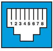
| No. | RS485 | CAN |
| 1 | RS485B / TRX- | |
| 2 | RS485A / TRX+ | |
| 3 | GND | |
| 4 | CAN-L | |
| 5 | CAN-H | |
| 6 | GND | |
| 7 | RS485A / TRX+ | GND |
| 8 | RS485B / TRX- |
A standard 8P8C 1:1 network cable can be used for the Parallel RS485 MODBUS connections between the battery.
Note: Please verify the inverter and battery pin out when establishing communication, a special patch cable may be required to establish communication. This cable is provided with the inverter. A standard 4P4C RS232 to USB converter cable can be used for the connections between the battery and the monitoring PC.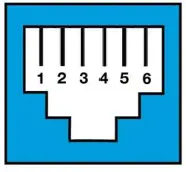
| No. | RS232 |
| 1 | |
| 2 | |
| 3 | TX |
| 4 | RX |
| 5 | GND |
| 6 |
Battery Management System Functionality
The Lithium Iron Phosphate cells are monitored and protected by an internal battery Management System (BMS) which provides a multitude of protection features such as:
- Over- and Under-voltage protection
- Charge and discharge over-current protection
- Short-circuit protection
- Over- and Under-temperature
In the case of any of the aforementioned protection, the BMS will disable charge or charging capability or shutdown the battery entirely to prevent damaging of the cells. The BMS will shut the battery down and enter a low power consumption mode if any of the following conditions are met:
- Cell or total pack under-voltage protections has not been released after 30s
- The minimum cell voltage is under the Sleep cell voltage and the duration exceeds the sleep delay while there is no communication, protection, cell balancing or battery current present.
- The battery is in Standby mode for more than 24 hours while there is no communication, protection, cell balancing or battery current present.
- Forced shutdown by pressing the RESET button for 3-6 seconds and then releasing.
Note: If the BMS enters low-power mode and shuts the battery down due to cell or total under voltage, the BMS will intermittently attempt to charge the battery every 4 hours for a total of 10 times, after which it will no longer automatically attempt to charge.
In order restart the battery and the cause the BMS to exit the low power sleep mode, any of the following conditions need to be met:
- Applying an external voltage greater than 48V but lower or equal to the Charge Voltage to the battery terminals.
- Pressing the RESET button for 3-6 seconds and then releasing.
Installation
Please read the installation manual of the inverter in conjunction with this product manual. All wiring, cable sizing and installation requirements must according to regulation with the specified installation requirements as governed by the relevant authority in the country of installation. Please ensure that a qualified installer familiar with the installation requirements is used for the installation. The installation details must be sent to Azoteq for the warranty to apply. Please download and complete the warranty document from the Azoteq website (https://www.azoteq.com/warranty/).
Hardware required
The following items are required to install the battery. Please note these items are not included with the battery.
- Positive (red) and Negative (black) power cables with M8 lugs on the battery side and M6 on the inverter side.
- Recommended cable thickness:
- ≥3 mm2 for 5kW installations
- ≥ 0mm2 for 8kW installations
- Recommended cable thickness:
- CANBUS or MODBUS communication cable (usually supplied with the inverter).
- Parallel communication cable when using multiple batteries.
- Ground cable and screw (M5) to earth the battery to the installation.
- DC overcurrent protection (fuse) and isolator for additional protection and compliance.
- It is recommended to install the batteries in a 19-inch rack mount cabinet.
- A cabinet with a fan will help circulate air to keep the batteries cool.
- The screws to fix the battery to the cabinet is provided with the battery.
Installation location
Please note the requirements for the installation location:
- The area needs to be dry.
- Relative humidity < 85%.
- Minimal dust.
- Ambient temperature between 0-40°C, ideally ~25°C.
- Frequent exposure to high temperatures will shorten the life of the battery.
- No flammable or explosive materials may be near the batteries.
Installation Procedure
- Make sure the breaker switch on the battery is in the OFF position.
- Install the battery inside the cabinet and secure it to the cabinet with the 4x mounting holes on the front sides.
- Please make sure the cabinet can support the weight of the battery / batteries.
- Connect the earth cable from the battery/batteries to the installation.
- Connect the power cables between the batteries (when using multiple batteries).
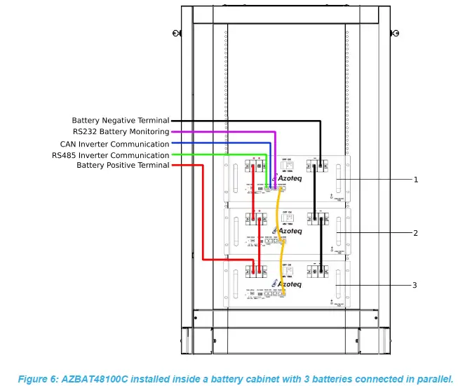
- Red and black cables as depicted in Figure 6.
- Please ensure the power cables are properly torqued to minimum 10N.m for the M8 terminal.
- Connect the cables to the inverter via the DC fuse and breaker.
- Please ensure the polarity of the connection between the inverter and the batteries are correct.
- Connect the RS485 cables between the batteries when using multiple batteries.
- As depicted by the yellow connections in Figure 6.
- Connect the CANBUS/RS485 cable between the master battery and the inverter.
- As depicted by the blue connection in Figure 6.
- Setup the DIP switches on the batteries for parallel use.
- Please refer to section 5.4 for more detail on the DIP switch settings.

- Please refer to section 5.4 for more detail on the DIP switch settings.
- Once the above has been done, please verify all the connections to ensure everything is as specified.
- Follow the instructions as specified in the installer manual before switching the batteries ON.
- When ready to switch the battery ON, flip the DC break switch to the ON position.
- Press and release the RESET switch on each of the batteries for the BMS to switch ON as the batteries are shipped in its SLEEP state.
- The green RUN LED will start flashing if everything is working.
- Refer to Table 3 for the LED indicator description.
- The inverter should automatically detect the BMS settings via the CANBUS/MODBUS connection once connected.
- Ensure the correct pin out of the communication cables.
- Verify that the battery is communicating with the BMS by checking the charging and discharging parameters on the inverter. The charge and discharge current values on the inverter should match the values as in Table 7. These values should update automatically on the inverter. The battery voltage, charge-and-discharge current, SoC value and battery temperature will be sent through to the inverter.
Please refer to figure 7 for successful battery communication displayed on a Deye inverter (Left) and an Axpert King inverter (Right) with the AZBAT48100C batteries.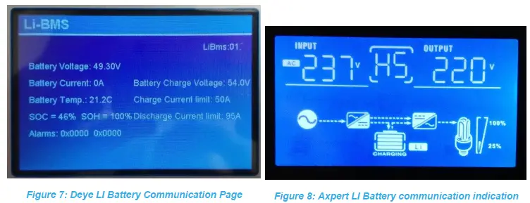
The figure on the left displays the charge and discharge information for an installation using 1 battery and communication to a Deye Inverter via the CAN port. The BMS communication is not successful if this information is incomplete or the displayed information page does not match this format. The figure on the right displays the Inverter operation diagram when using the RS485 port with a Axpert King inverter, the LI Icon next to the battery symbol indicates that there is communication with the BMS.
Parallel connection
When using more than one battery, the first battery will be the MASTER (Address 1) and the other batteries will be SLAVES (Address 2 – 15). The BMS must be reset to implement the Battery Addressing, this is done by pressing the RESET button for 9s and then releasing. The inverter communication (CAN or RS485) connection will be connected to the MASTER battery. The RS485 cable/s will link the parallel SLAVE batteries to the MASTER battery in a daisy chain fashion as shown in figure 6. The DIP switch (address) of the MASTER and the SLAVES need to be configured according to the number of batteries used. The DIP switch numbering is similar to a leading-least-significant digit four-bit number.
Please refer to the following table for the DIP switch settings:
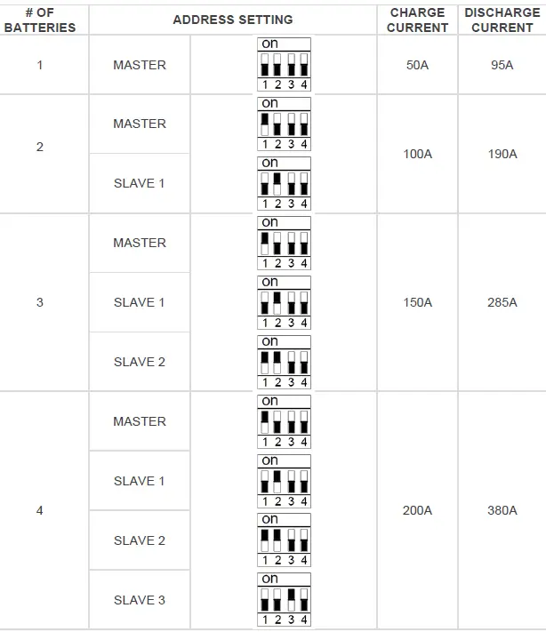
Note: The BMS needs to be reset with the RESET switch if adjusting the ADDRESS on the DIP switches.
Do not stack the batteries directly on top of each other when using multiple batteries in parallel. Each battery should be installed on a mounting plate to allow air circulation.
Table 8: Charge and Discharge current values
| # of Parallel | Charge Current (A) | Discharge Current (A) |
| 1 | 50 | 95 |
| 2 | 100 | 190 |
| 3 | 150 | 285 |
| 4 | 200 | 380 |
| 5 | 250 | 475 |
| 6 | 300 | 570 |
| 7 | 350 | 665 |
| 8 | 400 | 760 |
| 9 | 450 | 855 |
| 10 | 500 | 950 |
| 11 | 550 | 1045 |
| 12 | 600 | 1140 |
| 13 | 650 | 1235 |
| 14 | 700 | 1330 |
| 15 | 750 | 1425 |
Troubleshooting
Battery start-up procedure
In some cases the battery will go into a safe mode in the event of a short circuit or over-discharge. The Short Circuit Protection (SCP) circuit in the battery can potentially be activated when connected to an inverter or parallel battery for the first time. Since some inverters have large input capacitors, there is a significant inrush current from the battery to the capacitors inside the inverter which activates the SCP on the battery.
The BMS inside the battery switches off output voltage resulting in an open-circuit. This is visually evident when the display on the battery does not switch on. This can be confirmed by connecting a multi-meter on the terminals of the battery and measuring the voltage which should always be larger than 48Vdc. In the case of a shut-down the battery needs to be manually reset by following the procedure below:
- Connect AC power to the inverter after following the procedures as recommended in the inverter installation manual. With some inverters models the battery will automatically reset once power is applied to the inverter.
- If the battery did not switch ON, disconnect the AC power to the inverter.
- Use an isolated power supply or a battery charger with an output voltage of 48-54V and a current output larger 1A but less than 10A.
- Apply the voltage to the terminals of the battery for a few seconds until the voltage on the battery is >48V after which the external voltage source can be removed.
- The input capacitors on the inverter will remain charged while the battery is connected to the inverter.
Battery pack voltage is low or zero
- If the battery is fully charged it will open-circuit to prevent overcharging.
- Applying a load will reset the protection feature.
- If the battery has been in storage for a long period or over-discharged it will open-circuit to prevent further discharging.
- Follow the battery start-up procedure in Section 5.4 to re-energize the battery.
- Unstable battery voltage or irregular charging.
- Make sure that there is proper connections on the battery terminals.
- Battery voltage between 0V and 32V.
- The battery has been over-discharged and may have lost some capacity. Apply a charging voltage with a maximum of 10A charging current to re-energize the battery cells.
- If the battery voltage reaches 48V, increase the charging current and continue to charge to full capacity.
- Otherwise, immediately stop charging the battery as it has failed and will no longer hold charge. Continuing to charge such a battery will result in over-heating and eventually cause a fire or cell combustion.
Insufficient Energy Capacity
- Cycle the battery 4 – 5 times by discharging to 80% DoD and then charging with a charging current between 10A to 20A.
Precautions
Storage
- If the battery is stored for more than 3 months, it should be stored under environmentally controlled conditions:
- Ambient temperature: 25 ±3°C
- Humidity: 25-85% RH
- Air pressure: 86kPa-106kPa
- Do not store the battery in direct sunlight.
- The battery should be charged and discharged every 6 months.
- Battery storage SoC should be ~50%
Safety
Before use
- Inspect the battery to ensure that it is not damaged. If damaged, please inform the supplier.
- Ensure that the installation is done by a qualified installer.
- The installation needs to be done in compliance with the specified regulatory standards as required by governmental and local authorities.
- Make sure the breaker of the battery is in the OFF position.
- Ensure that the inverter is not powered from AC mains while connecting the battery.
- It is advised to use suitable protection between the battery and the inverter.
- Make sure the polarity (positive and negative) connections between the batteries (parallel use) and between the master/main battery and the inverter is correct.
- The batteries cannot be used in series as the BMS is designed for a 48V battery system.
- The battery/batteries need to be connected to earth and the earth resistance needs to be less than 1Ω.
- Verify that the inverter parameters match that of the battery.
- The battery should be kept away from heat, fire and water.
- Verify all connections before switching the breaker switch to the ON position.
During use
- In the event of altering or moving the installation, make sure that the breaker switch is in the OFF position. It is also recommended to switch the BMS OFF by press and holding the RESET switch down for a few seconds.
- Do not use this battery with that of another supplier or a different type of battery.
- Do not use the batteries with a faulty or incompatible inverter.
Emergency conditions
Please refer the material safety datasheet (MSDS) for the batteries on the Azoteq website.
Leaking cells
- In the event of a cell leaking liquid or gas, take caution to prevent any contact with the skin and eyes and inhaling the gas.
- Inhalation: Evacuate the contaminated area immediately and seek medical attention.
- Contact skin: Wash the affected area thoroughly with soap and water and seek medical attention.
- Contact with eyes: Rinse your eyes properly with water and seek medical attention.
Fire
- In the unlikely event of a fire, a dry chemical type extinguisher such as CO2 extinguisher will work effectively. DO NOT use water to extinguish the fire.
Other
- Wet batteries
- If the batteries are wet, please switch the battery OFF immediately.
- Please contact the supplier for further technical support.
- Damaged batteries
- If the batteries seem to be physically damaged, please do not switch them ON.
- Damaged batteries can be dangerous and need to be handled with care.
- Please contact the supplier for further technical support.
| USA | Asia | South Africa | |
| Physical Address | 6507 Jester Blvd Bldg 5, suite 510G Austin TX 78750 USA | Rm 1227, Glittery City Shennan Rd Futian District Shenzhen, 518033 China | 1 Bergsig Avenue Paarl 7646 South Africa |
| Postal Address | 6507 Jester Blvd Bldg 5, suite 510G Austin TX 78750 USA | Rm 1227, Glittery City Shennan Rd Futian District Shenzhen, 518033 China | PO Box 3534 Paarl 7620 South Africa |
| Tel | +1 512 538 1995 | +86 755 8303 5294 ext 808 | +27 21 863 0033 |
| Fax | +1 512 672 8442 | +27 21 863 1512 | |
| [email protected] | [email protected] | [email protected] |
Visit: www.azoteq.com
for a list of distributors and worldwide representation.
The following patents relate to the device or usage of the device: US 6,249,089; US 6,952,084; US 6,984,900; US 7,084,526; US 7,084,531; US 8,395,395; US 8,531,120; US 8,659,306; US 8,823,273; US 9,209,803; US 9,360,510; US 9,496,793; US 9,709,614; EP 2,351,220; EP 2,559,164; EP 2,748,927; EP 2,846,465; HK 1,157,080; SA 2001/2151; SA 2006/05363; SA 2014/01541; SA 2015/023634; SA 2017/02224;
AirButton®, Azoteq®, Crystal Driver, IQ Switch®, ProxSense®, ProxFusion®, Ligh s ™, wip wi h™, h logo are trademarks of Azoteq.
The information in this Datasheet is believed to be accurate at the time of publication. Azoteq uses reasonable effort to maintain the information up-to-date and accurate, but does not warrant the accuracy, completeness or reliability of the information contained herein. All content and information are provided on an “as is” basis only, without any representations or warranties, express or implied, of any kind, including representations about the suitability of these products or information for any purpose. Azoteq disclaims all warranties and conditions with regard to these products and information, including but not limited to all implied warranties and conditions of merchantability, fitness for a particular purpose, title and non-infringement of any third party intellectual property rights. Azoteq assumes no liability for any damages or injury arising from any use of the information or the product or caused by, without limitation, failure of performance, error, omission, interruption, defect, delay in operation or transmission, even if Azoteq has been advised of the possibility of such damages.
The applications mentioned herein are used solely for the purpose of illustration and Azoteq makes no warranty or representation that such applications will be suitable without further modification, nor recommends the use of its products for application that may present a risk to human life due to malfunction or otherwise. Azoteq products are not authorized for use as critical components in life support devices or systems. No licenses to patents are granted, implicitly, express or implied, by estoppel or otherwise, under any intellectual property rights. In the event that any of the abovementioned limitations or exclusions does not apply, it is agreed that Azoteq’s total liability for all losses, damages and causes of action (in contract, tort (including without limitation, negligence) or otherwise) will not exceed the amount already paid by the customer for the products. Azoteq reserves the right to alter its products, to make corrections, deletions, modifications, enhancements, improvements and other changes to the content and information, its products, programs and services at any time or to move or discontinue any contents, products, programs or services without prior notification. For the most up-to-date information and binding Terms and Conditions please refer to www.azoteg.com.
Copyright © Azoteq (Pty) Ltd 2021.
All Rights Reserved.
Revision 1.04


