RENOGY CF512100T1EC Lithium-Iron Phosphate Battery User Manual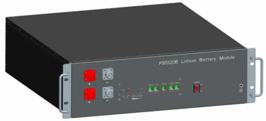
Introduction
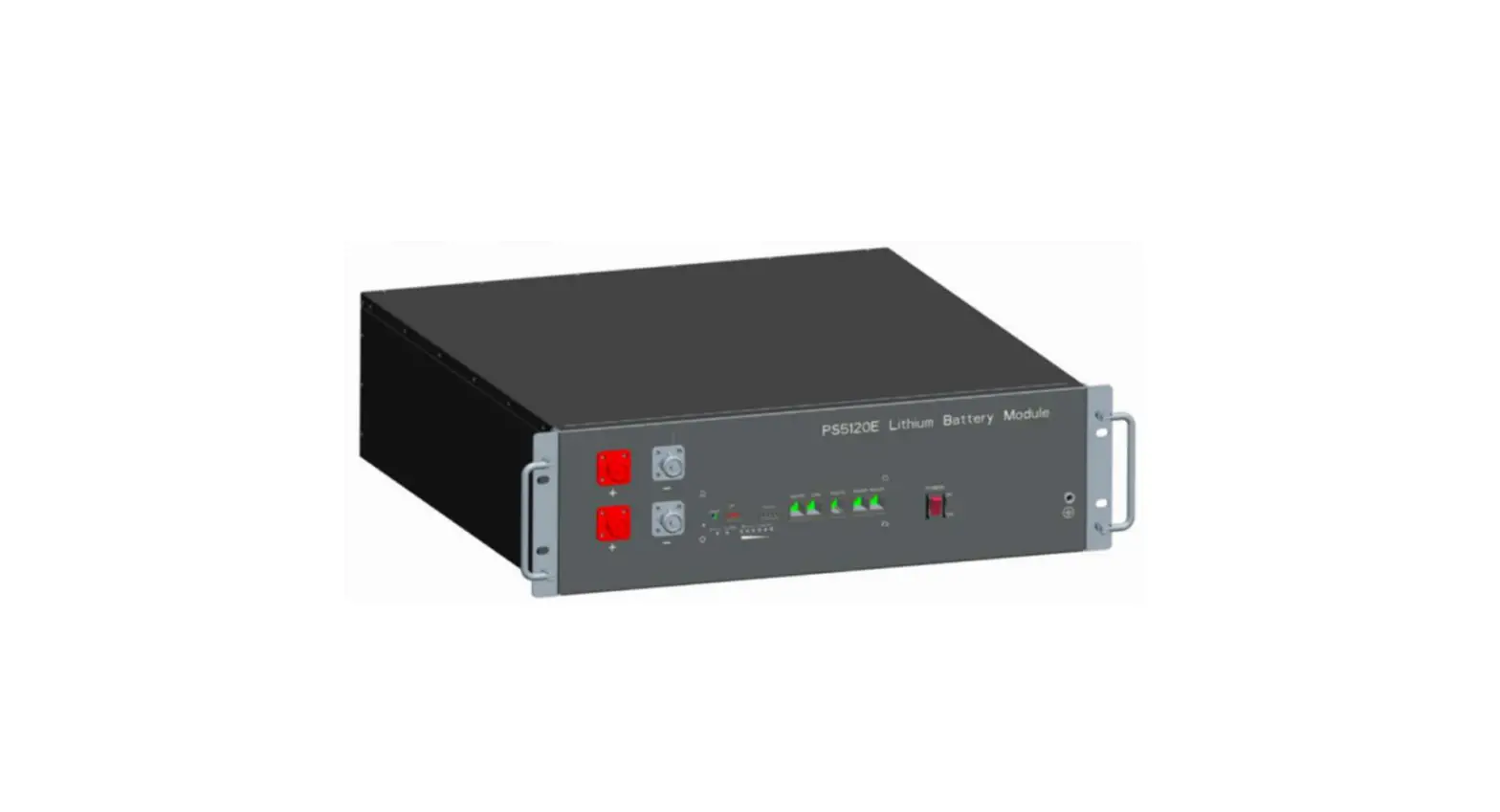
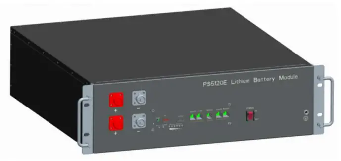
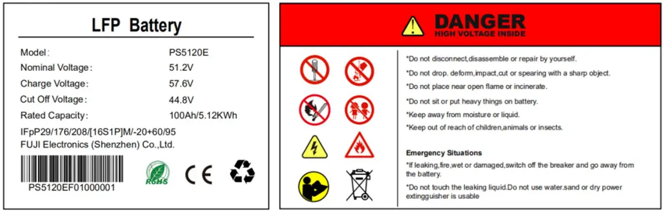
PS5120E lithium iron phosphate battery is one of new energy storage products developed and produced by manufacture, it can be used to support reliable power for various types of equipment and systems. PS5120E is especially suitable for application scene of high power, limited installation space, and restricted load-bearing and long cycle life.
PS5120E has built-in BMS battery management system, which can manage and monitor cells information including voltage, current and temperature. What’s more, BMS can balance cells charging and discharging to extend cycle life. Multiple batteries can connected in parallel to expand capacity and power in parallel for larger capacity and longer power supporting duration requirements.
Features:
- The whole module is non-toxic, non-polluting and environmentally friendly;
- Cathode material is made from LiFePO4 with safety performance and long cycle life;
- Battery management system (BMS)has protection functions including over-discharge, over-charge, over-current and high/low temperature;
- The system can automatically manage charge and discharge state and balance current and voltage of each cell;
- Flexible configuration, multiple battery modules can be in parallel for expanding capacity and power
- Adopted self-cooling mode rapidly reduced system entire noise;
The module has less self-discharge, up to 6 months without charging in on shelf; no memory effect, excellent performance of shallow charge and discharge; - Working temperature range is from -10℃ to 50℃, (Charging 0~50℃; discharging – 10~50℃) with excellent discharge performance and cycle life;
- Small size and light weight, standard of 19-inch embedded designed module is comfortable for installation and maintenance;
Specifications
| Basic Parameters | PS5120E |
| Nominal Voltage(V) | 51.2 |
| Nominal Capacity(Ah) | 100 |
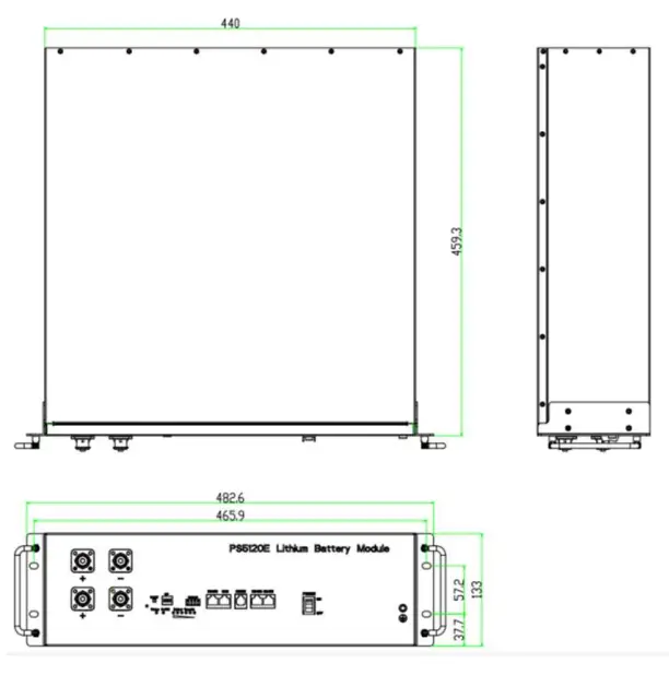
| Dimension(mm) | 459*440*133 |
| Weight(Kg) | 44 |
| Discharge Voltage(V) | 44.8 ~ 57.6 |
| MAX Discharge current (A) | 100 |
| Charge Voltage(V) | 57.6 |
| MAX Charge current (A) | 50 |
| Peak Discharge Power(W) | 10kW@30S |
| Peak Charge Power(W) | 5kW@30S |
| Communication | RS232,RS485,CAN |
| Working Temperature | 0℃~50℃ Charge |
| -10℃~50℃ Discharge | |
| Shelf Temperature | -20℃~60℃ |
| Certification | TÜV / UN38.3 /IEC62619 |
| Design life | 8+ Years(25℃/77℉) |
| Cycle Life | >6,000 (25℃ 90% DOD) |
Interfacing
This section details the front and back panel of the interface functions.
PS5120E Product Front Interface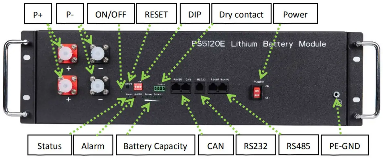
Status
Status light: to show the Power Switch is ON, and the BMS has electricity (No power).
ALARM
Alarm light: Battery failure status indicator light, red for failure, green for normal.
Battery Capacity
Battery Capacity: Power display, six indicator lights show the current power.
CAN
CAN Communication Terminal: (RJ45 port) follow CAN protocol, for output batteries information.
Definition of RJ45 Port Pin (CAN)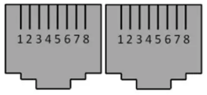
| No. | RJ45Pin | No. | RJ45Pin |
| 1, 8 | RS485B1 | 9,10,11,14,16 | NC |
| 2, 7 | RS485A1 | 12 | CANL |
| 3, 6 | GND | 13 | CANH |
| 4, 5, | NC | 15 | CAN_GND |
RS232
R232 Communication Terminal: (RJ11 port) follow RS232 protocol, for output batteries information.
Definition of RJ11 Port Pin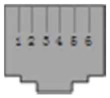
| No. | RJ11 Pin |
| 1 | NC |
| 2 | NC |
| 3 | TXD |
| 4 | RXD |
| 5 | GND |
| 6 | NC |
RS485
R485 communication terminal : (RJ45 interface) using RS485 protocol, output battery information, can also be used for multi-group lithium battery parallel communication.
Definition of RJ45 Port Pin 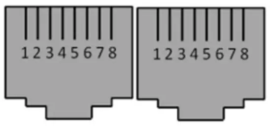
| No. | RJ45Pin | No. | RJ45Pin |
| 1, 8 | RS485B2 | 9,16 | RS485B2 |
| 2, 7 | RS485A2 | 10,15 | RS485A2 |
| 3, 6 | GND | 11,14 | CANH |
| 4, 5, | NC | 12,13 | CAN_GND |
PE-GND
PE-GND: Equipment case grounding.
Power Terminals(P+, P-)
Power cable terminals: there are two pair of terminals with same function, one connect to equipment, the other one paralleling to other battery module for capacity expanding. For each single module, each terminal can achieve charging and discharging function.
For power cables uses water-proofed AMPHENOL connectors. It must keep pressing this Lock Button during pulling out the power plug.
ON/OFF
ON/OFF Light: Constantly on after the boot, off after the extinguish
RESET
RESET Switch: When BMS is in hibernation state, press the button (3~6s) and release it, the protection plate will be activated, and the LED indicator will light up for 0.5 seconds successively from “RUN”.
When BMS is in the active state, press the button (3~6s) and release it, the protection board will sleep, and the LED indicator will light up for 0.5 seconds from the lowest battery level light.
When BMS is in the active state, press the button (6~10s) and release it, the protection plate is reset, and all LED lights are on for 1.5 seconds at the same time.
DIP (ADD)
DIP (ADD) Switch: 4 ADD switches, to definite different address code for each battery module when multiple modules are cascaded, up to 15 addresses.
NOTE: The address corresponding to ADD1 in the table is the host, and all other addresses are the slave。
| ADD | Dial code switch position | |||
| 1# | 2# | 3# | 4# | |
| 1 | ON | OFF | OFF | OFF |
| 2 | ON | ON | OFF | OFF |
| 3 | ON | ON | ON | OFF |
| 4 | ON | ON | ON | ON |
| 5 | ON | OFF | ON | OFF |
| 6 | OFF | ON | OFF | ON |
| 7 | OFF | OFF | OFF | ON |
| 8 | OFF | OFF | ON | ON |
| 9 | OFF | ON | ON | ON |
| 10 | OFF | ON | ON | OFF |
| 11 | ON | ON | OFF | ON |
| 12 | OFF | ON | OFF | OFF |
| 13 | ON | OFF | ON | OFF |
| 14 | ON | OFF | OFF | ON |
| 15 | OFF | OFF | ON | OFF |
Dry contact
Dry contact: Dry contacts are reserved for external I/O port control signals
Power
Power: to turn ON/OFF the whole battery BMS standby
LED Status Indicators
| Battery Statues | Protection / Alarm / Normal | On/ Off | Status | ALM | Capacity LED | Descriptions | |||||
| Shut Down | Sleep | Off | Off | Off | Off | Off | Off | Off | Off | Off | All Off |
| Standby | Normal | on | Flash 1 | Off | Based on capacity | Standby Status | |||||
| Alarm | on | Flash 1 | Flash 3 | The module of low pressure | |||||||
| Charge | Normal | Light | Light | Off | The highest capacity indicator LED flashes (flash 2), others lighting | ||||||
| Alarm | Light | Light | Flash 3 | Maximum power LED flashes(Flash2), overcharging ALM does not flash during alarm | |||||||
| Over charge Protection | Light | Light | Off | Light | Light | Light | Light | Light | Light | Stop charging | |
| Temp, current Protection | Light | Off | Light | Off | Off | Off | Off | Off | Off | Stop charging | |
| Discharge | Normal | Light | Flash 3 | Off | Based on capacity | ||||||
| Alarm | Light | Flash 3 | Flash 3 | ||||||||
| Under voltage Protection | Light | Off | Off | Off | Off | Off | Off | Off | Off | Stop discharging | |
| Temp, Over current , short, Protection | Light | Off | Light | Off | Off | Off | Off | Off | Off | Stop discharging | |
| Failure | Off | Off | Light | Off | Off | Off | Off | Off | Off | Stop discharging | |
BMS SOC DISPLAY
| Status | Charge | Discharge | |||||||||||
| SOC Light | L6 | L5 | L4 | L3 | L2 | L1 | L6 | L5 | L4 | L3 | L2 | L1 | |
| 0-16.6% | Off | Off | Off | Off | Off | FLASH2 | Off | Off | Off | Off | Off | Light | |
| 16.6-33.2% | Off | Off | Off | Off | FLASH2 | Light | Off | Off | Off | Off | Light | Light | |
| 33.2-49.8% | Off | Off | Off | FLASH2 | Light | Light | Off | Off | Off | Light | Light | Light | |
| 49.8-66.4% | Off | Off | FLASH2 | Light | Light | Light | Off | Off | Light | Light | Light | Light | |
| 66.4-83% | Off | FLASH2 | Light | Light | Light | Light | Off | Light | Light | Light | Light | Light | |
| 83-100% | FLASH2 | Light | Light | Light | Light | Light | Light | Light | Light | Light | Light | Light | |
| Status Light | Light | Flash3 | |||||||||||
LED flashing instructions:
| Flashing | Lighting Time | Closing Time |
| Flash1 | 0.25s | 3.75s |
| Flash2 | 0.5s | 0.5s |
| Flash3 | 0.5s | 1.5s |
BMS function:
| Protection and Alarm | Management and Monitor |
| Charge/Discharge End | Cells Balance |
| Charge Over Voltage | Intelligent Charge Model |
| Charge/Discharge Over Current | Charge Current Limit |
| High/Low Temperature | Capacity Retention Calculate |
| Short Circuit | Administrator Monitor |
| Power Cable Reverse | Operation Record |
Safe handling of lithium batteries Guide
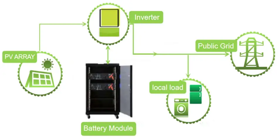
Schematic Diagram of Solution
Explanation of Symbol
Tools
The following tools are required to install the battery pack
Screw Driver 
NOTE
Use properly insulated tools to prevent accidental electric shock or short circuits.
If insulated tools are not available, cover the entire exposed metal surfaces of the available tools, except their tips, with electrical tape.
Safety protection
It is recommended to wear the following safety gear when dealing with the battery pack
Insulated gloves
Safety goggles
Safety shoes
The attachment list
| Name | Specification | Quantity |
| Positive power cable(short) | Amphenol terminal at both ends, cable length 58mm ,Red | 1 |
| Negative power cable(short) | Amphenol terminal at both ends, cable length 58mm ,Black | 1 |
| Communication parallel network cable | RJ45 terminals at both ends, cable length is 210mm | 1 |
| Grounding cable | OT terminals at both ends, cable length 200mm | 1 |
| Grounding cable screw | M5*10mm | 2 |
| Cabinet screw | M6*16mm | 4 |
| Cabinet Nut | Cage Nut M6 | 4 |
| User Operation Manual | PS5120E | 1 |
| Packing List | PS5120E | 1 |
| Warranty Card | PS5120E | 1 |
Installation
Package Items
For battery module package:
Two power cables and one communication cable for each battery package: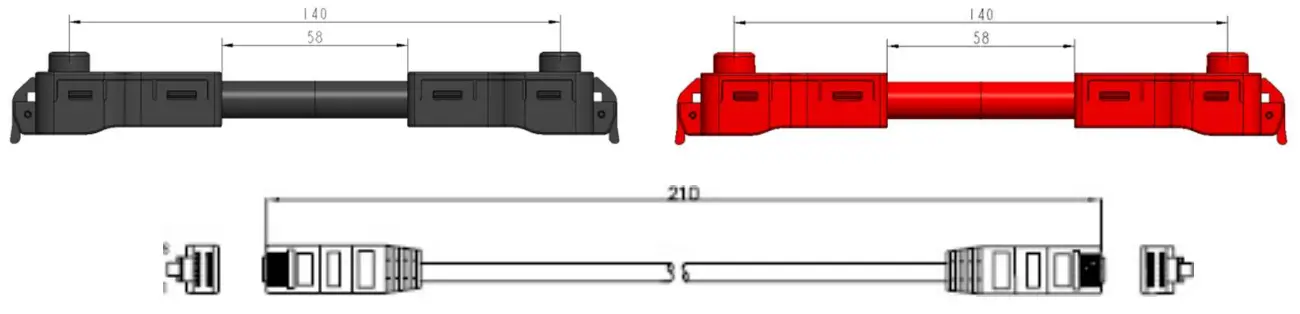
Grounding cable: 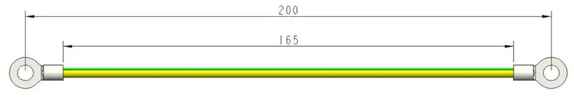
For battery system connects to inverter:
Two long power cables (current capacity 120A) and one communication cable for each energy storage system: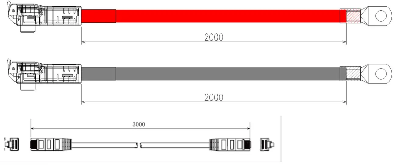
NOTE
These three long cables are NOT in battery package, they are option for selection. If there is anything missed please contact dealer.
Installation Condition
Make sure that the installation location meets the following conditions:
- he area is completely water proof.
- The floor is flat and level.
- There are no flammable or explosive materials.
- The ambient temperature is within the range from 0°C to 50°C.
- The temperature and humidity is maintained at a constant level.
- There is minimal dust and dirt in the area.
CAUTION

If the ambient temperature is outside the operating range, the battery pack stops operating to protect itself. The optimal temperature range for the battery pack to operate is 0°C to 50°C. Frequent exposure to harsh temperatures may deteriorate the performance and life of the battery pack.
Installation Procedure
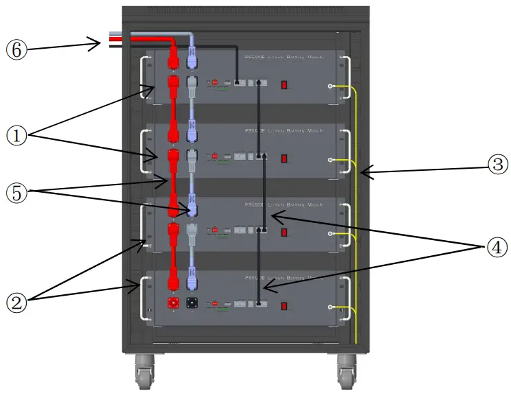
- Put the battery into the cabinet;
Drive the 4 pcs screws; - Connect the Ground cables between battery modules
- Connect the Communication cable between battery modules
- Connect the cables between battery modules
- Connect the cables to inverter
A. Power On
Double check all the power cable and communication cable.
Switch power on
Switch on all the battery modules and the green LED light below will be on: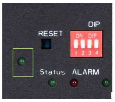
Master and slave Settings
| ADD | Dial code switch position | ||||
| 1# | 2# | 3# | 4# | ||
| 1 | ON | OFF | OFF | OFF | Master |
| 2 | ON | ON | OFF | OFF | Slave |
| 3 | ON | ON | ON | OFF | Slave |
| 4 | ON | ON | ON | ON | Slave |
| 5 | ON | OFF | ON | OFF | Slave |
| 6 | OFF | ON | OFF | ON | Slave |
| 7 | OFF | OFF | OFF | ON | Slave |
| 8 | OFF | OFF | ON | ON | Slave |
| 9 | OFF | ON | ON | ON | Slave |
| 10 | OFF | ON | ON | OFF | Slave |
| 11 | ON | ON | OFF | ON | Slave |
| 12 | OFF | ON | OFF | OFF | Slave |
| 13 | ON | OFF | ON | OFF | Slave |
| 14 | ON | OFF | OFF | ON | Slave |
| 15 | OFF | OFF | ON | OFF | Slave |
Note: Only the Master can communicate with the inverter
Master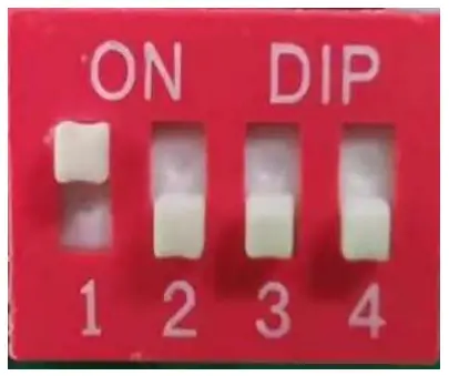
Slave1
Slave 2
Parallel connection mode
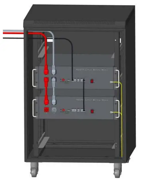
A. The two modules are in parallel
Normal parallel mode, as shown in the right picture
Parallel parameter:
Charge Voltage :57.6V
Max Charge current : 100A
Max Discharge current :100A
Rate parallel mode, as shown in the right picture
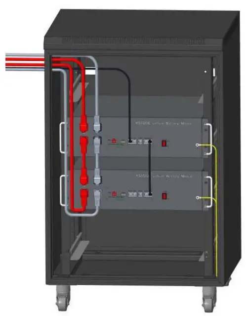
Parallel parameter:
Charge Voltage :57.6V
Max Charge current : 200A
Max Discharge current :200A
NOTE: If all the battery LED lights on, and then off, which means the battery system is good and working.
Rate parallel mode, Connect the two positive output terminals of the battery together, the two negative terminals together, and finally to the device
B. The four modules are in parallel
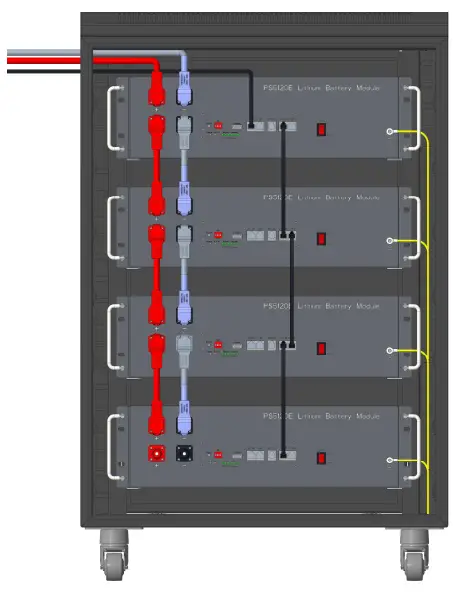
Normal parallel mode, as shown in the right picture
Parallel parameter:
Charge Voltage :57.6V
Max Charge current : 100A
Max Discharge current :100A
Rate parallel mode, as shown in the right picture
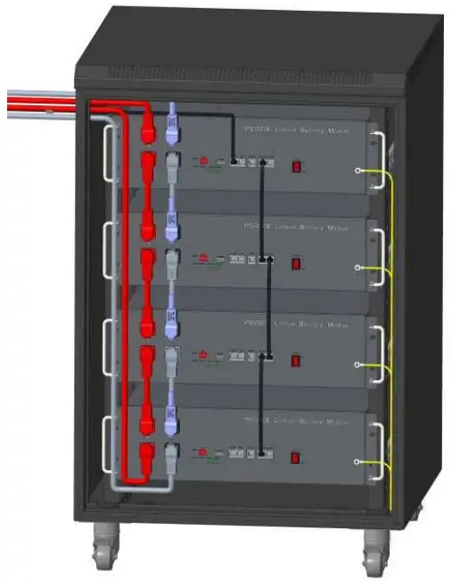
Parallel parameter:
Charge Voltage :57.6V
Max Charge current : 200A
Max Discharge current :200A
NOTE: If all the battery LED lights on, and then off, which means the battery system is good and working.
Rate parallel mode connect the two positive output terminals of the battery together, the two negative terminals together, and finally to the device.
Safety Precautions
![]() Warning
Warning
Precautions before installation
- After unpacking, please check product and packing list first, if product is damaged or lack of parts, please contact with the local retailer;
- Before installation, be sure to cut off the grid power and make sure the battery is in the turned-off mode;
- Wiring must be correct, do not mistake the positive and negative cables, and ensure no short circuit with the external device;
- It is prohibited to connect the battery and AC power directly;
- The embedded BMS in the battery is designed for 48VDC, please DO NOT connect battery in series;
- Battery system must be well grounded and the resistance must be less than 1Ω;
- Please ensured the electrical parameters of battery system are compatible to related equipment;
- Keep the battery away from water and fire.
Notes in the process of use
- If the battery system needs to be moved or repaired, the power must be cut off and the battery is completely shut down;
- It is prohibited to connect the battery with different type of battery.
- It is prohibited to put the batteries working with faulty or incompatible inverter;
- It is prohibited to disassemble the battery (QC tab removed or damaged);
- In case of fire, only dry powder fire extinguisher can be used, liquid fire extinguishers are prohibited;
- Please do not open, repair or disassemble the battery except staffs from Manufacture or authorized by dealer. We do not undertake any consequences or related responsibility which because of violation of safety operation or violating of design, production and equipment safety standards.
![]() Reminded
Reminded
- Please read the user manual carefully (in the accessories);
- If the battery is stored for long time , it is required to charge them every six months, and the SOC should be no less than 80%;
- Battery needs to be recharged within 12 hours, after fully discharged;
- Do not expose cable outside;
- All the battery terminals must be disconnected for maintenance;
- Please contact the supplier within 24 hours if there is something abnormal.
- The warranty claims are excluded for direct or indirect damage due to items above.
Troubleshooting
Troubleshooting Steps
- Whether the battery can turn on or not;
- If battery is turned on, check the red light is off, flashing or lighting;
- If the red light is off, check whether the battery can charge/discharge or not.
Fault identification procedure :
Battery cannot turn on, switch on the lights are all no lighting or flashing.
If the battery external switch is ON, the Status light is flashing, and the external power supply voltage is 48V or more, the battery still unable to turn on, please contact dealer.
The battery can be turned on, but red light is lighting, and cannot charge or discharge. If the red light is lighting, that means system is abnormal, please check values as following:
Temperature: Above 55℃ or under -20 , the battery could not work. ℃
Solution: to move battery to the normal operating temperature range between -10℃ and 50℃
Current: If current is greater than 100A, battery protection will turn on.
Solution: Check whether current is too large or not, if it is, to change the settings on power supply side.
High Voltage: If charging voltage above 57.6V, battery protection will turn on.
Solution: Check whether voltage is too high or not, if it is, to change the settings on power supply side.
Low Voltage: When the battery discharges to 44.8V or less, battery protection will turn on.
Solution: Charge the battery for some time, the red light turn off
Excluding the four points above, if the faulty is still cannot be located, turn off battery and repair.
Charging fault troubleshooting
- Cannot be charged:
Disconnect the power cables, measure voltage on power side, if the voltage is 53~54V, restart the battery, connect the power cable and try again, if still not work, turn off battery and contact dealer. - Unable to discharge:
Disconnect the power cables and measure voltage on battery side, if it is under 44.8V, please charge the battery; if voltage is above 48V and still cannot discharge, turn off battery and contact dealer.
Emergency Situations
Leaking Batteries
If the battery pack leaks electrolyte, avoid contact with the leaking liquid or gas. If one is exposed to the leaked substance, immediately perform the actions described below.
Inhalation: Evacuate the contaminated area, and seek medical attention.
Contact with eyes: Rinse eyes with flowing water for 15 minutes, and seek medical attention.
Contact with skin: Wash the affected area thoroughly with soap and water, and seek medical attention.
Ingestion: Induce vomiting, and seek medical attention.
Fire
NO WATER! Only dry powder fire extinguisher can be used; if possible, move the battery pack to a safe area before it catches fire.
Wet Batteries
If the battery pack is wet or submerged in water, do not let people access it, and then contact Manufacture or an authorized dealer for technical support.
Damaged Batteries
Damaged batteries are dangerous and must be handled with the utmost care. They are not fit for use and may pose a danger to people or property. If the battery pack seems to be damaged, pack it in its original container, and then return it to Manufacture or an authorized dealer.


