![]()
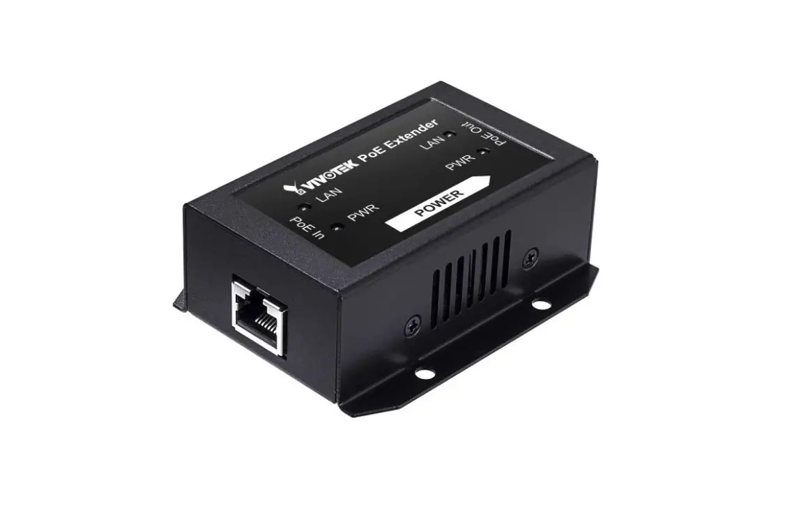
AP-GXC-0100 & AP-GXC-0200 Gigabit PoE Extender
Quick Installation Guide
INTRODUCTION
AP-GXC-0100: 1 PoE IN – to – 1 PoE OUT.
AP-GXC-0200: 1 PoE IN – to – 2 PoE OUT.
The AP-GXC-0100 & AP-GXC-0200is a Gigabit PoE Extender capable of receiving 30W/60W/90W power from PSE. Multiple extenders can be cascaded to increase the cabling distance.
PACKAGE CONTENTS
- 1x PoE Extender
- 1x Quick Installation Guide
 IMPORTANT:
 IMPORTANT:
- Install the device in a ventilated and dry place, that is free of electromagnetic source, vibration, moisture, and dust.
- Make sure the ventilation openings on the extender are not blocked.
- Use CAT.5e or 6 UTP/STP cables. Avoid using low-quality cables, which will seriously limit the cabling distance.
CONNECTION
Following are the conditions for making the cabling:
- Use 18~19, 24AWG CAT.5e cables.
- Typical cameras stream size feature = 1080p@30fps – 6Mbps; 720p@30fps – 3Mbps.
Make sure the combined bandwidth consumption does not exceed the uplink bandwidth from the PoE switch.
NOTE: There are power losses due to cable resistance.
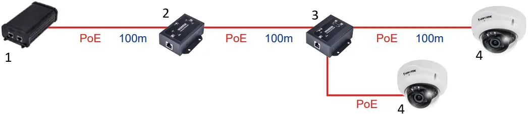
- 90W bt PoE Injector
- AP-GXC-0100
- AP-GXC-0200
- PoE Camera
INSTALLATION
AP-GXC-0100
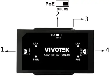
- PoE Input Connect to PoE Switch
- PoE OFF/ON Switch
- Ground screw
 * Make sure the grouning resistance is lower than 0.5Ω.
 - 56VDC PoE Output
AP-GXC-0200
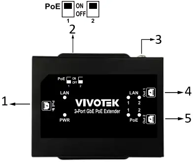
- PoE Input Connect to PoE Switch
- PoE OFF/ON Switch
- Ground screw* Make sure the grouning resistance is lower than 0.5Ω.
- Port 1 : 56VDC PoE Output
- Port 2 : 56VDC PoE Output
LED DEFINITIONS
| PWR | Green ON | PoE IN port is connected to PSE. |
| OFF | No PoE IN connection. | |
| PoE | Green ON | Power over ethernet cable status |
| OFF | Ethernet cable no Power | |
| LAN | Green ON | Data link is detected. |
| Green Flashing | Data is being transmitted or received. | |
| OFF | Link is not detected. |
PoE DIP SWITCH DEFINITIONS
AP-GXC-0100
| DIP# | ON | Turn on PoE output for the PoE out port. |
| OFF | Turn off PoE output for the PoE out port. |
AP-GXC-0200
| Pin 1 | ON | Port 1 Turn on PoE output |
| OFF | Port 1 Turn off PoE output | |
| Pin 2 | ON | Port 2 Turn on PoE output |
| OFF | Port 2 Turn off PoE output |
**If the device that is going to be connected to this extender is not PoE PD, please turn off the PoE output function.**
All specifications are subject to change without noice.
Copyright © 2022 VIVOTEK INC. All rights reserved.
VIVOTEK INC.
6F, No.192, Lien-Cheng Rd., Chung-Ho, New Taipei City, 235, Taiwan, R.O.C.
|T: +886 -2-82455282|F: +886-2-82455532|E:[email protected]
VIVOTEK USA, INC.
2050 Ringwood Avenue, San Jose, CA 95131
|T:408-773-8686|F: 408-773-8298|E:[email protected]
VIVOTEK Europe
Zandsteen 15, 2132 MZ Hoofddorp Delta Electronics
T:+31 (0)20 800 3817 E:[email protected]


