SeeEyes SC-IPE3001 IP PoE Extender
Precaution and Safety Guidelines
The content of this guideline is to protect the safety of users and prevent property damage. Please be sure to read this user’s manual thoroughly and use the device correctly.
Warning (If you do not keep any of the below guidelines, you may get
seriously injured or cause somebody’s death.)
- Be sure to install the product after unplugging power cord. Also, do not use many power plugs at the same time.
- It may cause abnormal heat, fire and electric shock.
- Do not leave the device in a place where water will fall or splash. Also, do not place anything with water on it, such as a vase of flowers.
- A malfunction or fire may result if liquid gets inside the device
- Do not bend the power cord by excessive force. Make sure the power cord is not crushed by heavy things.
- It may cause fire.
- Do not open the lid arbitrarily as this device has high voltage part inside. Never disassemble, repair or modify it.
- Abnormal work could result in fire, electric shock, and injury.
- Do not install this product in places with high humidity, dust, or soot.
- It may cause electric shock and fire.
- Do not tug at the power cord section or unplug the power plug with wet hands. If the power cord is loose, do not plug in.
- There may be a risk of fire and electric shock.
- Keep the device in a cool place where doesn’t let direct sunlight. Keep it at a proper temperature and avoid heating appliances like candle or heater. Also, keep the equipment or tools away from places where people come and go.
It may cause fire. - Pay attention to possible hazards in the workplace, such as wet floor, ungrounded power extension cables, old power cords and a lack of safety earth. Consult your place of purchase or professional if problems arise.
- It may cause fire and electric shock.
- Concerning the input voltage for operating this device, a voltage range must be within 10% of rated voltage. Also, do not use a heat source such as a hair dryer, iron and refrigerator to the same power unit.
- It may cause abnormal heat, fire and electric shock.
Caution (If you do not keep any of the below guidelines, you may get injured or suffer property loss.)
- Avoid installing near strong magnetic fields or radio waves and wireless devices such as radio
- Install in a place that is free from magnetic, radio, or excessive vibration.
- Proper ambient temperature and humidity are recommended.
- Avoid extremely high temperatures(over 50°C) or low(below -10°C), and humid conditions.
- Do not place heavy items on the product or let foreign substances enter inside the device.
- It may cause failure.
- Install in well ventilated place, and avoid direct sunlight or heat appliance.
- Install at a flat and stable place. Do not use an upright or slanted position.
- It may not operate properly or might be dangerous due to the fall of the device.
- Strong shock or vibration may cause device failure. Be careful when using the device.
- Install in a place without severe vibration.
- If you notice any unusual noise or smell, unplug the power supply immediately and contact the place of purchase or service center.
- There may be a risk of fire and electric shock.
- Rotate the air properly in the system operating room and secure the cover of the main body.
- It may be the cause of failure by environmental factors.
- Refer the device to the service center and get regular checkup to maintain the performance of the system.
- We are not responsible for any damages caused by user’s carelessness.
- Be sure to plug the power cord with grounded outlet.
- There is a risk of electrical shock and personal injury.
- Place the power plug in a location that is easy to operate.
- If a failure of the product occurred, the power plug must be unplugged to power down completely. The power button on the main body does not completely disconnect power.
- Disconnect the power plug with care during thunder and lightning.
- Install the cable as “U” shape in order to prevent rain water/dew/fog, etc. from falling through the cable.
- UTP(Unshielded Twisted Pair) Cable is for indoor use only. Use a STP(Shield Twisted Pair) Cable which is covered for outdoor use.
- Use standard UTP cable such as CAT.5e or above.
- Do not design and configure general network(Internet/indoor) together with CCTV network.
- It might be the cause of problem.
- Refer to the user’s manual for problems or questions besides the above. Contact our service center if you need assistance from a professional technician.
Introduction
Overview
SC-IPE3001 is a 1-channel UTP Ethernet Data + PoE Extender. With its built-in power supply function (PoE IEEE802.3at), this product supplies power to camera over UTP 1 cable.
To compensate the short transmission distance of Network equipment (below 100m), SC-IPE3001 extends the transmission distance up to 100~250m by installing this product in the UTP cable section between camera and PoE HUB.
Also, it is able to reduce construction costs by supplying PoE to IP camera.
Features
- Transmit power + IP data over 1 UTP Cable(CAT.5e).
- TCP Rate : 100Mbps Full Duplex
- Extend Ethernet Data transmission up to 100~250m by adding 1 pc of SC-IPE3001.(Add/extend the product after checking the rated capacity of IP camera you use.)
- Auto MDI/MDIX
- Built-in surge protection circuit
- Power input: DC 48~56V Adapter or PoE (DC Adapter power priority)
- Extend transmission distance by setting bandwidth switch (100Mbps/10Mbps). 100Mbps setting : Transmit up to 100m (CAT.5e)
10Mbps setting : Transmit up to 250m (CAT.5e)
Make sure to turn the power of the product OFF/ON after changing the setting value.
Components
| SC-IPE3001 | Power Cord, Adapter | Manual |
 | Power Cord, Adapter(Option) |  |
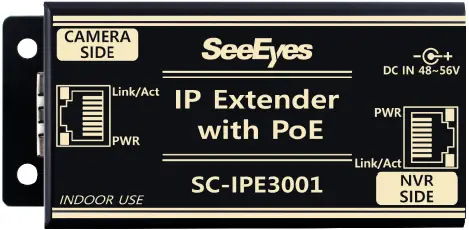
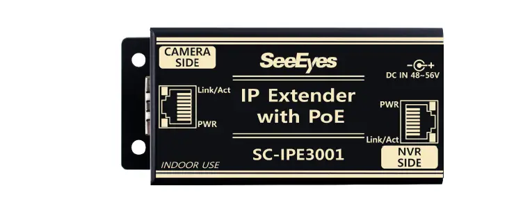
Product Parts & Functions
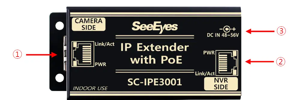
CAMERA SIDE : IP PoE camera connection port..
- Port to supply PoE and receive data from camera.
| LED | LED Indicator | |
| Yellow | ON | Successful Power Input |
| OFF | No Power Input | |
| Green | ON | Connected to Camera |
| Blinking | Successful Data Transmission | |
| OFF | No Data Transmission | |
NVR SIDE : NVR or PoE Switch HUB connection port.
- Port to receive power from PoE Switch HUB / PoE Injector and supply power and data to camera.
| LED | LED Indicator | |
| Yellow | ON | Successful PoE Input |
| OFF | No PoE Input | |
| Green | ON | Successful LINK connection to NVR or network device |
| Blinking | Successful Data connection to NVR or network device | |
| OFF | No LINK connection to NVR or network device | |
DC IN 48~56V : DC 48~56V input port (Able to be used as an Injector.)
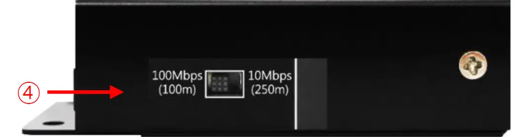
Bandwidth Select Switch : Switch to select network speed (100Mbps, 10Mbps setting)
- Able to change network speed by setting the switch as 100Mbps<->10Mbps.
| Transmission Speed | Max. Transmission Distance |
| 100Mbps | Max. 100m(CAT.5e) |
| 10Mbps | Max. 250m(CAT.5e) |
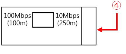
- Make sure to turn the power of the product OFF/ON after changing the setting value.
- The initial setting is set to 100Mbps.
Connection Diagrams
Basic Connection with Receiving Power from DC 48/56V Adapter
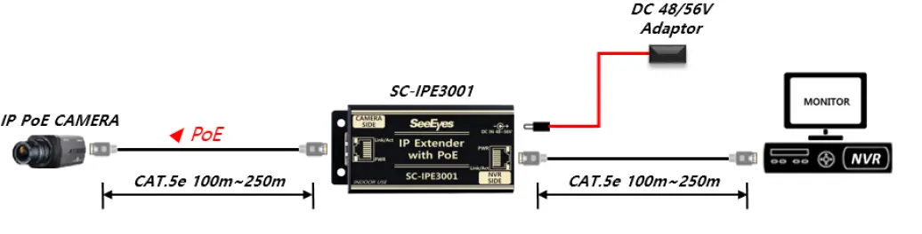
- Bandwidth Switch 100Mbps Setting : Transmit Max. 100m (CAT.5e)
- Bandwidth Switch 10Mbps Setting : Transmit Max. 250m (CAT.5e)
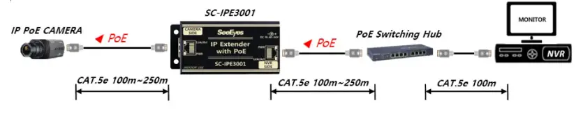
Basic Connection with Receiving Power from PoE Switching HUB
- Bandwidth Switch 100Mbps Setting : Transmit Max. 100m (CAT.5e)
- Bandwidth Switch 10Mbps Setting : Transmit Max. 250m (CAT.5e)
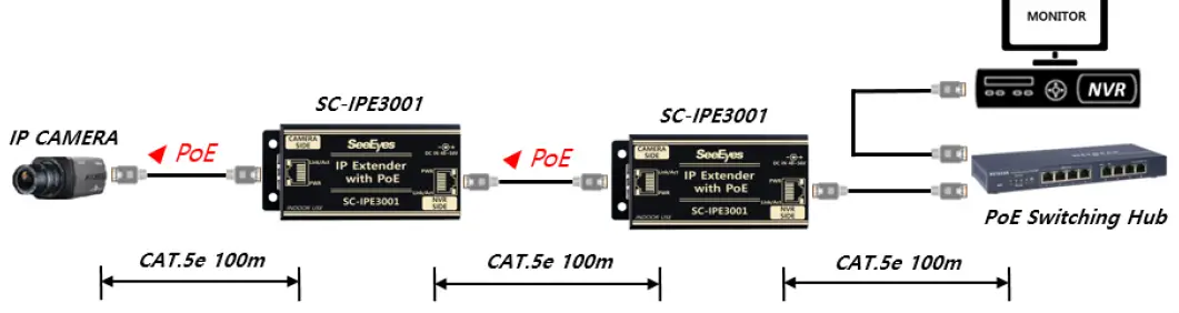
Multiple Connection with 2 pcs of SC-IPE3001 in 100Mbps
 Multiple Connection with 2 pcs of SC-IPE3001 in 10Mbps
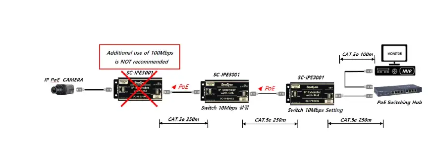
- Able to extend as above figure. The max. extension distance may vary depending on the rated capacity of IP camera, characteristics of the cable, and the added SC-IPE3001 quantity.
- Network Link-time may be longer as the number of Extenders is increased.
- Setting Bandwidth Switch as 100Mbps : Transmit Max. 100m (CAT.5e)
- Setting Bandwidth Switch as 10Mbps : Transmit Max. 250m (CAT.5e)
- If the bandwidth exceeds 10Mbps after setting the Bandwidth Switch to 10M, there may be a problem with the video.
- Max. Power Output in SC-IPE3001 100Mbps Setting (Using DC Adapter)
| SC-IPE3001 Power Input | SC-IPE3001 Connection Quantity | Max. Power Output 100Mbps/100m |
| DC 48V | 1 | 38W |
| 2 | 16W | |
| 3 | 9W | |
| 4 | 5W | |
| DC 56V | 1 | 48W |
| 2 | 30W | |
| 3 | 18W | |
| 4 | 12W |
- When using SC-IPE3001 as a PoE Injector, Max. power output is 35W (using DC 48V Adaptor).
- Max. Power Output in SC-IPE3001 100Mbps Setting (Using PoE)
| SC-IPE3001 Power Input | SC-IPE3001 Connection Quantity | Max. Power Output 100Mbps/100m |
| PoE | 1 | 14W |
| 2 | 10W | |
| 3 | 6W | |
| 4 | 3W | |
| PoE+ | 1 | 25W |
| 2 | 20W | |
| 3 | 14W | |
| 4 | 9W |
Max. Power Output in SC-IPE3001 10Mbps Setting
| SC-IPE3001 Power Input | Max. Power Output 10Mbps/250m | |
| SC-IPE3001 x1 | SC-IPE3001 x2 | |
| DC 48V | 15W | 6W |
| DC 56V | 28W | 13W |
| PoE | 7W | 3W |
| PoE+ | 13W | 8W |
- It is not recommended to use 100Mbps and 10Mbps simultaneously when connecting more than 2 SC-IPE3001.
(In this case, the communication speed of 2 SC-IPE3001 is set to 10Mbps.) - When connecting a camera with large power consumption or inrush current, please use a 56V adapter or apply PoE+ to the product.
CABLE PIN Configuration
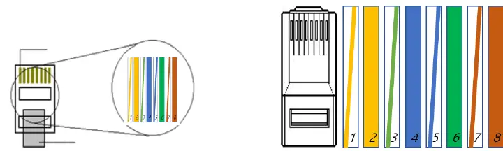
| No. | Color | Color | Function | |
| 1 | Orange + White | White | Orange | TX+ |
| 2 | Orange | Orange | TX- | |
| 3 | Green + White | White | Green | RX+ |
| 4 | Blue | Blue | PWR+ | |
| 5 | Blue + White | White | Blue | PWR+ |
| 6 | Green | Green | RX- | |
| 7 | Brown + White | White | Brown | PWR- |
| 8 | Brown | Brown | PWR- | |
Troubleshooting
| Symptom | Identification Method |
| No Power |
|
| No Video |
|
| Unstable Video |
(Transmission video quality, frame rate, resolution, etc.)
|
| Unstable Network |
|
7. Specifications
| Model No. | SC-IPE3001 | |
| Power Input | DC | DC 48V or DC 56V Adapter |
| PoE | PoE IEEE 802.3af / 802.3at, Endspan / Midspan (Mode A / Mode B) | |
| Feature | DC Adapter power supply priority (Between DC Adapter and PoE) | |
| PoE Output | Midspan only (Mode B) | |
| Power Consumption | 0.5W Max. | |
| Max. Transmission Distance | In 100Mbps : Max. 100m (CAT.5e) | |
| In 10Mbps : Max. 250m (CAT.5e) | ||
| Transmission Bandwidth | 10/100Mbps (Full duplex) | |
| RJ-45 Connector Pin Assignment(Polarity) | 1Pin: TX(+), 2Pin: TX(-), 3Pin: RX(+), 4Pin: PWR(+) | |
| 5Pin: PWR(+), 6Pin: RX(-), 7Pin: PWR(-), 8Pin: PWR(-) | ||
|
LED Indicator |
CAMERA SIDE | YELLOW ON : Power Input |
| YELLOW OFF : No Power Input | ||
| Green ON : Connected to Camera | ||
| Green Blinking : Normal Data Transmission | ||
| Green OFF : No Data Transmission | ||
|
NVR SIDE | YELLOW ON : Power Input | |
| YELLOW OFF : No Power Input | ||
| Green ON : Connected to NVR | ||
| Green Blinking : Normal Data Transmission | ||
| Green OFF : No Data Transmission | ||
| Max. Power Output | 25.5W based on IEEE802.3at Power Device (This may vary depending on the condition of the cable and the number of connected products.) | |
| Bandwidth Switch | Transmission Bandwidth Settings: 100Mbps or 10Mbps | |
| Connection Port | CAMERA SIDE | RJ-45 1Port (TIA/EIA568B Type) |
| NVR SIDE | RJ-45 1Port (TIA/EIA568B Type) | |
| POWER | DC JACK | |
| Temperature / Humidity | -10°C~+50°C / 0 ~ 80% | |
| Case Material / Weight | Aluminum / 64g | |
| Dimensions (mm) | 88(W) x 42(H) x 25(D) mm | |
- Using the LAN cable extension gender (coupler) causes signal attenuation. The use of multiple gender connections is not recommended.
- Cable transmission distance may vary depending on the specifications of camera and NVR.
- When using the camera PoE function, the transmission distance may vary depending on the type of camera.
Warranty Certificate
This product has passed thorough quality control and test, and if this gets broken during normal use, we provide the two-year warranty service.
| Model No. | ||
| Serial No. | ||
| Distributor | ||
| Date you purchased | ||
| Place you purchased | ||
| Warranty Period | Two (2) year from the date of purchase | |
| Purchaser | Name | |
| Address | ||
- Please check this warranty indication first.
- Please contact your distributor after checking out any defect in the products.
- The standard for repairing, replacement or reimbursement follows Customer.
- Warranty content any defect under normal use within the warranty service period we give you free repair service according to the warranty certificate.
- We charge you with the fee of parts and service despite of free warranty service period. Any breakage made without care such as:
- Breakdown due to natural disasters (lightning, fire, flood, tsunami, etc.)
- When disassembled or repaired by the user
- When connecting power other than rated power.
- When you want to reassemble for full system or replace parts within warranty service period.
- When unauthorized person modified or made damage on the product trying to repair it.
- Failure due to careless handling of the user
- When replacing consumables
- Lightning strike.
- Please note that we don’t support the breakage after warranty service period expired. If the customer wants to get it repaired, we charge them with the fee.
- The specification is subject to change without prior notice for quality improvement.
SeeEyes Co., Ltd
#50 3 ~50 9 , 511~512, Sunil Technopia, 555 Dunchon daero , Jungwon g u,
S eong nam City , Gyeonggi Province , Korea (Zip Code:
TEL: +82 –(0)31 730 58 33
FAX: +82 –(0)31 777 3512
EMAIL: [email protected]
http://www.sscctv.com /eng


