i3 INTERNATIONAL IP01P PoE Over Coax Extender User Manual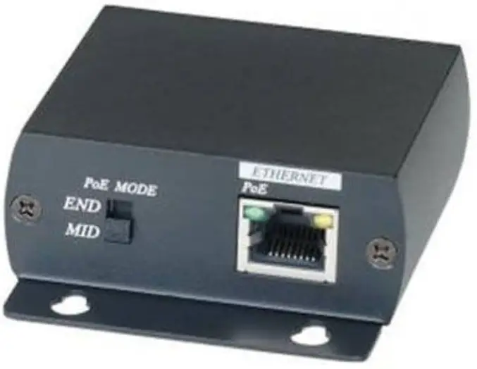
Introduction
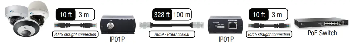
Thank you for purchasing i3 International’s IP01P PoE extender (sold in pairs). Use IP01P as a point-to-point PoE (Power over Ethernet) extender to power IP devices and to carry IP signal for distances of up to 328 feet (100 meters) using existing coaxial cable infrastructure. Use with i3’s line of IP cameras and PoE switches.
INSTALLATION
Figure 1. IP01P connection diagram.
WARNING
Unplug power before switching between MID SPAN and END SPAN modes to avoid damage to the device.
CONNECTORS
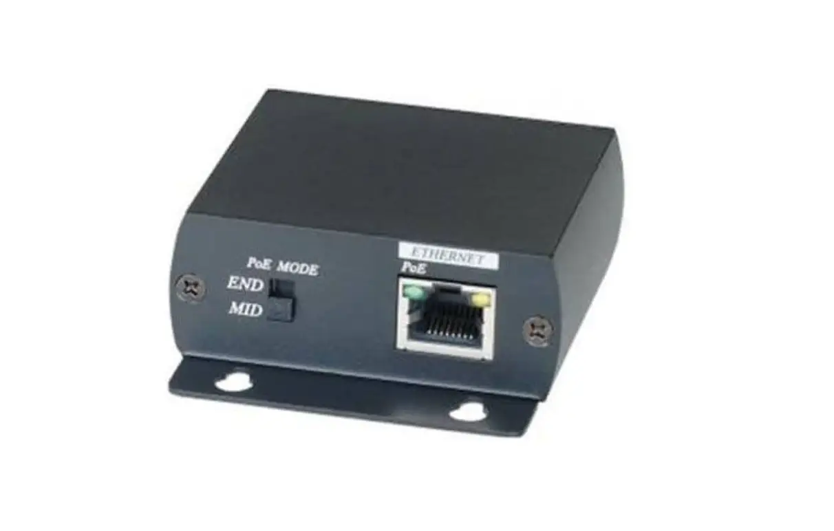
Figure 2. IP01P front and back panels, parts description.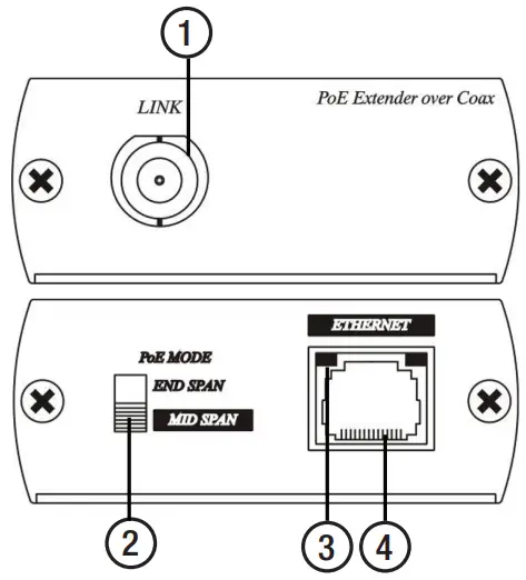
- BNC Connector. Connect to the second IP01P device using the RG59 cable, 328 ft (100 m) or less.
The link speed is up to 10 Mbps. - PoE Mode Selector Switch. Pre-set to MID SPAN setting (recommended). See Tables 2, 3.
IMPORTANT: Unplug power before switching between MID SPAN and END SPAN modes to avoid damage. - Power LED Indication. Indicates device power status. See Table 1.
- RJ45 Connector. Connect one IP01P to the PoE IP device and the other to PoE Switch.
Do not exceed 10 ft (3 m) cable run between IP01P and PoE equipment.
FEATURES
- Signal extension up to 328 ft (100 m) over RG59/RG6U
coaxial cable. - Power from a PoE switch or injector.
- Bandwidth up to 10Mbps.
- Use with i3’s PoE cameras and with i3 PoE switches.
Note: M79, Ax85, Ax19 are not supported.
PACKAGE CONTENTS
- IP01P x2 (one pair)
- Crossover cable x2 (8 in / 20 cm)
- Plastic Anchor x4
- Round Head Screw (Tapping Type) x4
Figure 3. IP01P front and back panels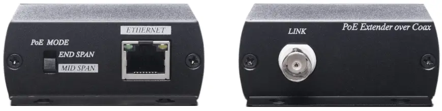
POWER STATUS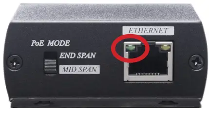
| Green ON | Green OF |
| Power ON | Power OFF |
POE MODE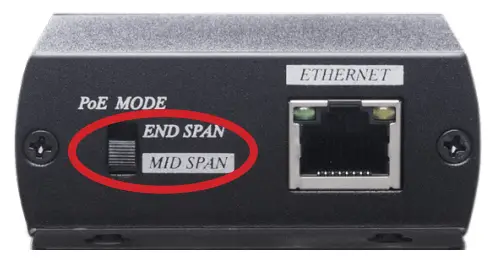
Table 2. PoE Mode Selector
| Mode | RJ45 pin# for power transmission |
| END SPAN | 1/2 and 3/6 |
| MID SPAN (Default), Recommended | 4/5 and 7/8 |
PIN LAYOUT
Table 3. END SPAN / MID SPAN Pin Layout
| PIN | Color | MID SPAN END SPAN Default, recommended | |
| 1 | White Orange | TX+ | TX+ / PoE + |
| 2 | Orange | TX- | TX- / PoE + |
| 3 | White Green | RX+ | RX+ / PoE – |
| 4 | Blue | PoE+ | |
| 5 | White Blue | PoE+ | |
| 6 | Green | RX- | RX- / PoE – |
| 7 | White Brown | PoE- | |
| 8 | Brown | PoE- | |
RJ45 CABLE CONNECTION
Figure 4. IP01P RJ45 cable connection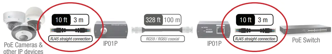
- Ethernet cable length must not exceed 10 ft (3 m)
- Straight connection is recommended when using MID SPAN.
- If the RJ45 Power Status LED is OFF, or when using END SPAN, use one of the other cable connection combinations
until the LED turns ON. - RJ45 cable connection combinations. Two crossover patch cables are provided.
- Straight + Straight (recommended, use with MID SPAN)
- Straight + Crossover (use with END SPAN)
- Crossover + Straight (some non-i3 PoE cameras)
- Crossover + Crossover (some non-i3 PoE cameras)
SPECIFICATION
| !POI P | |
| Compliance | IEEE 802.3af Power over Ethernet IEEE 802.3at Power over Ethernet Plus |
| Bandwidth | 10 Mbps |
| Max. Transmission Distance | 10Mbps @ 328 ft (100 m) |
| Ports & Interfaces | |
| Input | 1 x RJ45 |
| Output | 1 x 750 BNC |
| Power | |
| Power Consumption | 1.25W (Max) |
| Environmental specifications | |
| Operation | 32-131 °F (0-55 °C) |
| Storage | -4-185 °F (-20-85 °C) |
| Humidity | 5 95% |
| Physical Characteristics | |
| Dimensions | 25/6″ x 3 7/16″ x 1 VIC (67 x 87 x 27mm) |
| Weight | 0.33 lbs (150 g) |
REGULATORY NOTICES (FCC CLASS A)
 This device complies with Part 15 of the FCC Rules.
Operation is subject to the following two conditions:
- This device may not cause harmful interference, and
- This device must accept any interference received, including interference that may cause undesired operation.
NOTE: This equipment has been tested and found to comply with the limits of a Class A digital device, pursuant to Part 15 of the FCC rules.
These limits are designed to provide reasonable protection against harmful interference when the equipment is operated in a commercial environment. This equipment generates, uses, and can radiate radio frequency energy and, if not installed and used in accordance with the instruction manual, may cause harmful interference to radio communications. Operation of this equipment in a residential area is likely to cause harmful interference in which case the user will be required to correct the interference at his own expense.
Customer Support
Scan this QR code or visit ftp.i3international.com for Annexxus Configuration Tool (ACT) installation and additional documentation.
Scan Me
FTP://ftp.i3international.com
Contact our Technical Support team at:
1.877.877.7241 or [email protected] if you have any questions or concerns
regarding camera installation or if you require
software services or support.