![]() QSFP-100G-LR-AR-CW31-AO Single Lambda Transceiver
QSFP-100G-LR-AR-CW31-AO Single Lambda Transceiver
User Manual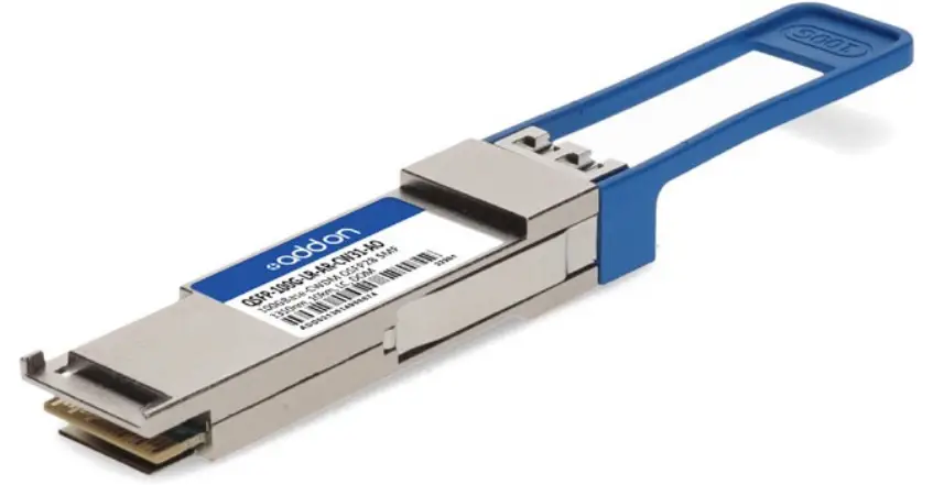
QSFP-100G-LR-AR-CW31-AO Single Lambda Transceiver
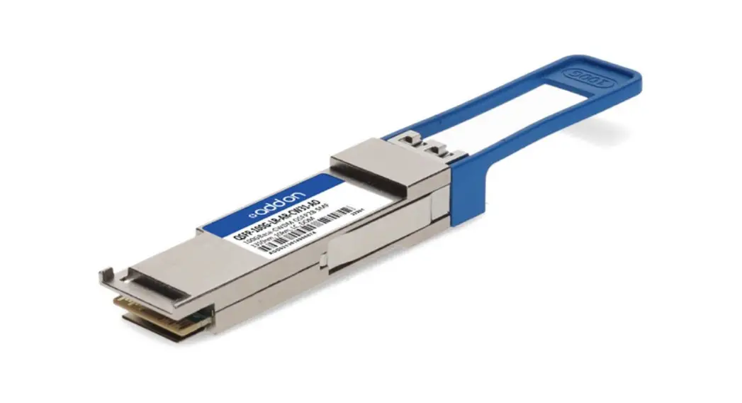
QSFP-100G-LR-AR-CW31-AO
Arista Networks® QSFP-100G-LR-AR-CW31 Compatible TAA Compliant 100GBase-CWDM QSFP28 Single Lambda Transceiver (SMF, 1310nm, 10km, LC, DOM, with FEC)
Features:
- Supports 100Gbps
- 100G Lambda MSA 100G-LR Specification Compliant
- Single 3.3V Power Supply
- Power Dissipation < 4.5W
- Up to 10km over SMF with FEC
- QSFP28 MSA Compliant
- SFF-8636 Rev 2.10a Compliant
- 4x25G Electrical Interface
- LC Duplex Connector
- Operating Case Temperature: 0°C to 70°C
- I2C Interface with Integrated Digital Diagnostic Monitoring
- RoHS compliant
Applications:
- 100G Ethernet
- Data Center
Product Description
This Arista Networks® QSFP-100G-LR-AR-CW31 compatible QSFP28 transceiver provides 100GBase-CWDM throughput up to 10km over single-mode fiber (SMF) using a single lambda wavelength of 1310nm via an LC connector. It is guaranteed to be 100% compatible with the equivalent Arista Networks® transceiver. This easy-to-install, hot-swappable transceiver has been programmed, uniquely serialized and data traffic and application tested to ensure that it will initialize and perform identically. Digital optical monitoring (DOM) support is also present to allow access to real-time operating parameters. This transceiver is Trade Agreements Act (TAA) compliant. We stand behind the quality of our products and proudly offer a limited lifetime warranty.
AddOn’s transceivers are RoHS-compliant and lead-free.![]() TAA refers to the Trade Agreements Act (19 U.S.C. & 2501-2581), which is intended to foster fair and open international trade. TAA requires that the U.S. Government may acquire only “U.S. made or designated country end products.”
TAA refers to the Trade Agreements Act (19 U.S.C. & 2501-2581), which is intended to foster fair and open international trade. TAA requires that the U.S. Government may acquire only “U.S. made or designated country end products.”
Regulatory Compliance
- ESD to the Electrical PINs: compatible with MIL-STD-883E Method 3015.4
- ESD to the LC Receptacle: compatible with IEC 61000-4-3
- EMI/EMC compatible with FCC Part 15 Subpart B Rules, EN55022:2010
- Laser Eye Safety compatible with FDA 21CFR, EN60950-1& EN (IEC) 60825-1,2
- RoHS compliant with EU RoHS 2.0 directive 2015/863/EU
CWDM Available Wavelengths
| Wavelengths | Min. | Typ. | Max. |
| 27 | 1264.5 | 1271 | 1277.5 |
| 29 | 1284.5 | 1291 | 1297.5 |
| 31 | 1304.5 | 1311 | 1317.5 |
| 33 | 1324.5 | 1331 | 1337.5 |
Absolute Maximum Ratings
| Parameter | Symbol | Min. | Typ. | Max. | Unit |
| Maximum Supply Voltage | Vcc | -0.5 | 4.0 | V | |
| Storage Temperature | TS | -40 | +85 | °C | |
| Operating Case Temperature | Tc | 0 | 70 | °C | |
| Operating Relative Humidity | RH | 5 | 85 | % | |
| Damage threshold | Rxdmg | 5.5 | dBm |
Electrical Characteristics
| Parameter | Symbol | Min. | Typ. | Max. | Unit | Notes |
| Power Supply Voltage | Vcc | 3.135 | 3.3 | 3.465 | V | |
| Power Dissipation | PD | 4.5 | W | |||
| Transmitter | ||||||
| Differential data input swing per lane | 900 | mVp-p | ||||
| Differential input impedance | Zin | 90 | 100 | 110 | ohm | |
| DC common mode voltage (Vcm) | -350 | 2850 | mV | |||
| Receiver | ||||||
| Differential output amplitude | 900 | mVp-p | ||||
| Differential output impedance | Zout | 90 | 100 | 110 | ohm | |
| Output Rise/Fall Time | tr/tf | 12 | ps | 20%~80% | ||
| AC Common Mode Output Voltage | 7.5 | mV | ||||
| Eye width | 0.57 | UI | ||||
| Eye height differential | 228 | mV | @TP4, 1E-15 | |||
| DC common mode voltage (Vcm) | -350 | 2850 | mV | 1 | ||
Notes: 1. Vcm is generated by the host. Specification includes effects of ground offset voltage.
Optical Characteristics
| Parameter | Symbol | Min. | Typ. | Max. | Unit | Notes |
| Transmitter | ||||||
| Signaling speed | 53.125 | Gbaud | ||||
| Modulation format | PAM4 | |||||
| Optical center wavelength | λ | λc–6.5 | λc | λc+6.5 | nm | |
| Side-mode suppression ratio | SMSR | 30 | dB | |||
| Extinction ratio | ER | 3.5 | dB | |||
| Transmit OMA | TxOMA | 0.7 | 4.7 | dBm | ||
| Transmit average | TxAVG | -1.4 | 4.5 | dBm | 1 | |
| Launch power in OMAouter minus TDECQ | -0.7 | dBm | 2 | |||
| Launch power in OMAouter minus TDECQ | -0.6 | dBm | 3 | |||
| Transmitter and dispersion eye closure | IDEC | 3.4 | dB | |||
| Optical return loss tolerance | 15.6 | dB | 4 | |||
| Receiver | ||||||
| Signaling speed | 53.125 | Gbaud | ||||
| Damage threshold | 5.5 | dBm | ||||
| Receive power (OMAouter) | Roma | 4.7 | dBm | |||
| Average receive power | RxAVG | -7.7 | 4.5 | dBm | ||
| Receiver sensitivity (OMAouter) | Sonoma | Max(-6.1, SEC-7.5) | dBm | 5 | ||
| Receiver reflectance | -26 | dB | ||||
| LOS assert | LOSA | -15 | dBm | |||
| LOS De-assert | LORD | -12 | dBm | |||
| LOS hysteresis | 0.5 | dB | ||||
Notes:
- Average launch power (min) is informative and not the principal indicator of signal strength. A transmitter with launch power below this value cannot be compliant; however, a value above this does not ensure compliance.
- For ER4.5dB
- For ER<4.5dB
- Transmitter reflectance is defined as looking into the transmitter.
- Sensitivity is specified at 2.4×10⁻⁴ BER.
Pin Descriptions
Pin | Symbol | Name/Descriptions | Ref. |
| 1 | GND | Transmitter Ground (Common with Receiver Ground) | 1 |
| 2 | Tx2- | Transmitter Inverted Data Input | |
| 3 | Tx2+ | Transmitter Non-Inverted Data output | |
| 4 | GND | Transmitter Ground (Common with Receiver Ground) | 1 |
| 5 | Tx4- | Transmitter Inverted Data Input | |
| 6 | Tx4+ | Transmitter Non-Inverted Data output | |
| 7 | GND | Transmitter Ground (Common with Receiver Ground) | 1 |
| 8 | Modell | Module Select | 2 |
| 9 | reset | Module Reset | 2 |
| 10 | VccRx | 3.3V Power Supply Receiver | |
| 11 | SCL | 2-Wire serial Interface Clock | 2 |
| 12 | SDA | 2-Wire serial Interface Data | 2 |
| 13 | GND | Transmitter Ground (Common with Receiver Ground) | 1 |
| 14 | Rx3+ | Receiver Non-Inverted Data Output | |
| 15 | Rx3- | Receiver Inverted Data Output | |
| 16 | GND | Transmitter Ground (Common with Receiver Ground) | 1 |
| 17 | Rx1+ | Receiver Non-Inverted Data Output | |
| 18 | Rx1- | Receiver Inverted Data Output | |
| 19 | GND | Transmitter Ground (Common with Receiver Ground) | 1 |
| 20 | GND | Transmitter Ground (Common with Receiver Ground) | 1 |
| 21 | Rx2- | Receiver Inverted Data Output | |
| 22 | Rx2+ | Receiver Non-Inverted Data Output | |
| 23 | GND | Transmitter Ground (Common with Receiver Ground) | 1 |
| 24 | Rx4- | Receiver Inverted Data Output | 1 |
| 25 | Rx4+ | Receiver Non-Inverted Data Output | |
| 26 | GND | Transmitter Ground (Common with Receiver Ground) | 1 |
| 27 | ModPrsl | Module Present | |
| 28 | IntL | Interrupt | 2 |
| 29 | VccTx | 3.3V power supply transmitter | |
| 30 | Vcc1 | 3.3V power supply | |
| 31 | LPMode | Low Power Mode | 2 |
| 32 | GND | Transmitter Ground (Common with Receiver Ground) | 1 |
| 33 | Tx3+ | Transmitter Non-Inverted Data Input | |
| 34 | Tx3- | Transmitter Inverted Data Output |
| 35 | GND | Transmitter Ground (Common with Receiver Ground) | 1 |
| 36 | Tx1+ | Transmitter Non-Inverted Data Input | |
| 37 | Tx1- | Transmitter Inverted Data Output | |
| 38 | GND | Transmitter Ground (Common with Receiver Ground) | 1 |
Notes:
- The module signal grounds are isolated from the module case.
- This is an open collector/drain output that on the host board requires a 4.7K to 10K pull-up resistor to VccHost.
Electrical Pin-out Details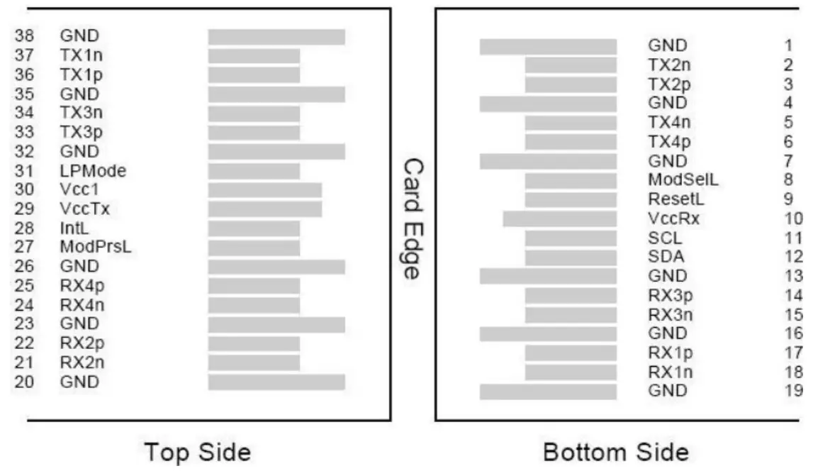
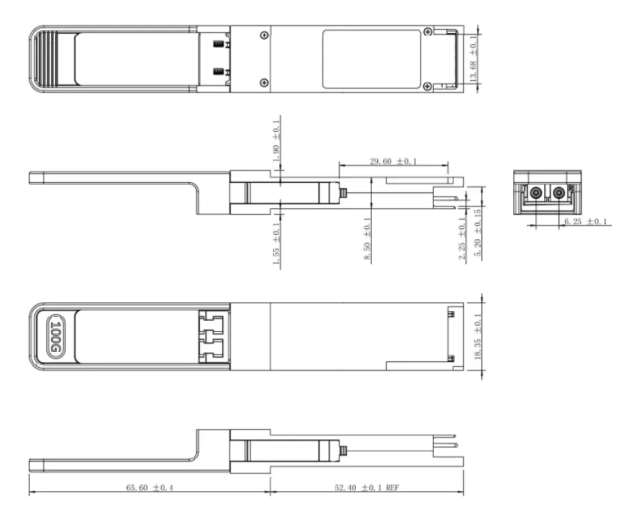
Mechanical Specifications
 About AddOn Networks
In 1999, AddOn Networks entered the market with a single product. Our founders fulfilled a severe shortage of compatible, cost-effective optical transceivers that compete at the same performance levels as leading OEM manufacturers. Adhering to the idea of redefining service and product quality not previously had in the fiber optic networking industry, AddOn invested resources in solution design, production, fulfillment, and global support.
Combining one of the most extensive and stringent testing processes in the industry, an exceptional free tech support center, and a consistent roll-out of innovative technologies, AddOn has continually set industry standards of quality and reliability throughout its history.
Reliability is the cornerstone of any optical fiber network and is engrained in AddOn’s DNA. It has played a key role in nurturing the long-term relationships developed over the years with customers. AddOn remains committed to exceeding industry standards with certifications ranging from NEBS Level 3 to ISO 9001:2005 with every new development while maintaining the signature reliability of its products.
![]() U.S. Headquarters
U.S. Headquarters
Email: [email protected]
Telephone: +1 877.292.1701
Fax: 949.266.9273
Europe Headquarters
Email: [email protected]
Telephone: +44 1285 842070
www.addonnetworks.com
Phone: 877.292.1701


