Generic QlS2800s Signal Generator User Manual
Overview
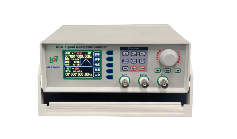
The qls2800s series of instruments use large-scale fpga integrated circuits and 32-bit high-speed arm microprocessors. The internal circuit adopts a surface mount process, which greatly improves the anti-interference and service life of the instrument. The display interface adopts a 2.4-inch tft LCD screen with 320*240 high resolution, which can display all the parameters of the channel and prompt the current button functions, effectively utilize the button resources, avoiding frequent user button operations, greatly enhanced. Operability. The instrument has great advantages in signal generation, waveform scanning, parameter measurement and use. It is an ideal test and measurement equipment for electronic engineers, electronic laboratories, production lines and teaching and research.
The model
This series of instruments is divided into two models, the main difference is the maximum frequency of the output sine wave, as follows:
QLS2806S sinusoidal signal frequency up to 5MHz, amplitude up to 10Vp-p;
The instrument characteristics
- using direct digital synthesis (dds) technology, fpga design, ultralow power consumption;
- a single dc5v power adapter power supply, easy to carry;
- using 2.4 inch tft true color LCD screen, with variable function buttons and rotary encoder, greatly enhanced the ease of use of the machine;
- Basic function waveforms such as sine wave, triangle wave, square wave, saw tooth wave, and pulse wave with adjustable duty cycle;
- the output signal frequency can be as small as 0.01 Hz;
- There are 10 sets of parameter storage bits of m0~m9, and the data of m0 is automatically called up when booting;
- the waveform frequency resolution is at least 0.01Hz, and the amplitude resolution is at least 10mV;
- with manual trigger, external trigger two trigger mode, can make the machine output 1~999999 arbitrary pulse Rushing
- the pulse wave duty cycle adjustment is accurate to 0.5%;
- Frequency scanning with an end point;
- with frequency measurement, counting function;
- All parameters can be calibrated by internal procedures;
- powerful communication functions, completely open communication protocol, making secondary development very simple;
- after connecting with the PC, can use the pc to control the instrument.
Technical indicators
project | parameter | ||
| Main characteristics | Frequency Range | Sine wave | QLS2802S:0Hz~2MH: QLS2805S: 0Hz~5MHz: |
| Square wave | 0Hz~2MHz | ||
| Triangle wave | 0Hz~2MHz | ||
| Sawtooth wave | 0Hz~2MHz | ||
| Output modulation | Frequency scanning, bursting | ||
| Waveform typ | Sine wave, square wave, triangle wave, sawtooth wave | ||
| Frequency error | ±8×10⁻⁶ | ||
| Frequency stability | ±5×10⁻⁶ | ||
| Amplitude range (peak-to-peak) | 10mVp-p~10Vp-p; | ||
| Output impedance | 50Ω±10% | ||
| Amplitude resolution | 10mVp-p | ||
| Amplitude stability | ±0.5% (every 5 hours) | ||
| Amplitude error | ± 1% + 10mV (frequency 1KHz, 8 Vp-p) | ||
| Offset range | -100%~+100% | ||
| Sine wave | Harmonic resistance system | 40dBc( | |
| Distortion | <0.8%(20Hz~20KHz) | ||
| Square wave | Lifting time | ≤28ns | |
| Overshoot | ≤10% | ||
| Duty cycle adjustment range | 0.1%~99.9% | ||
| TTL/CMOS | Lifting time | ≤28ns | |
| Low level | <0.3V | ||
| High level | 1V~5V | ||
| Sawtooth wave | Duty cycle >50.1% | Rising sawtooth | |
| Duty cycle <49.9% | Sawtooth wave | ||
| scanning | Scan mode | Sweep | |
| Scan time | 0.1S~999.9S | ||
| Scanning range | 0-Max.Freq | ||
| External measurement function | Minimum input voltage | 0.5Vp-p | |
| Maximum allowable input voltage | 10Vp-p | ||
| Counting range | 0~4294967295 | ||
| Counting method | Manual | ||
| Source selection | Ext.IN input (analog signal) | ||
| storage | Quantity | 10 | |
| position | M0 to m9 | ||
| interface | interface | Use usb to serial interface | |
| Communication rate | 57600 bps | ||
| Protocol | Using the command line, the agreement is open | ||
| power supply | DC | 5V | |
| size | Length × width × height | 170×200×70mm | |
| weight | Stand-alone | 518g | |
Panel description
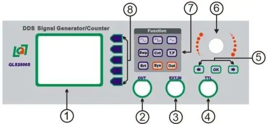
1 | Data display area | 5 | Operation button |
| 2 | Waveform output port | 6 | Code knob |
3 | External signal input port | 7 | function button |
4 | Ttl signal output port (synchronous out) | 8 | Auxiliary operation button |
Display instructions
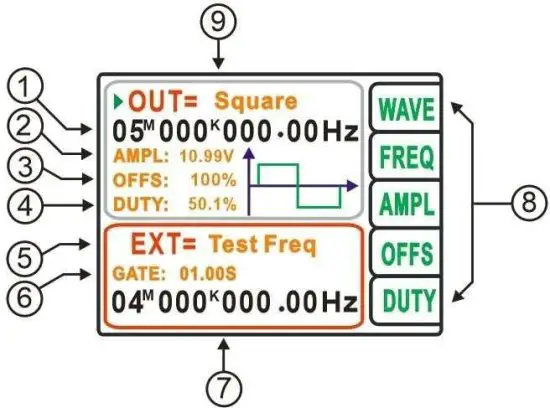
1 | Output frequency display | 6 | Gate time |
| 2 | Amplitude | 7 | Measuring frequency |
3 | Bias | 8 | Function option |
| 4 | Duty cycle | 9 | Output waveform |
5 | Measurement function | 10 | air |
Operating instructions
set the waveform
In the main interface, click the ![]() button, then rotate the adjustment knob to change the output waveform.2, set the frequency.
button, then rotate the adjustment knob to change the output waveform.2, set the frequency.
Click on the main interface ![]()
![]() Button, click The button changes the frequency adjustment step value , and then the adjustment knob increases or decreases the out put wave form frequency value.
Button, click The button changes the frequency adjustment step value , and then the adjustment knob increases or decreases the out put wave form frequency value.
the amplitude setting
Click the ![]() button in the main
button in the main ![]() interface, click the button Change the amplitude adjustment step value, then adjust the knob to increase or decrease the amplitude value of the output waveform.
interface, click the button Change the amplitude adjustment step value, then adjust the knob to increase or decrease the amplitude value of the output waveform.
offset adjustment
Click the ![]() button in the main interface
button in the main interface ![]() click The button changes the duty cycle adjustment step value, and then the adjustment knob increases or decreases the duty cycle of the output square wave.
click The button changes the duty cycle adjustment step value, and then the adjustment knob increases or decreases the duty cycle of the output square wave.
pulse counting function
Click the “Cnt” button, the cursor jumps to the frequency measurement function display page, and the main page displays the function option on the right side to switch to the status shown in Figure 6-1 below. Connect the signal to be tested to the Ext. In interface, and then click the button to start the frequency measurement ![]() . ) function, click the
. ) function, click the ![]() button to pause the frequency measurement function, and click the
button to pause the frequency measurement function, and click the ![]() button to clear the frequency measurement value.
button to clear the frequency measurement value.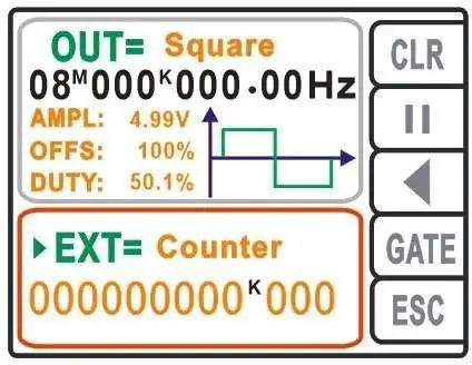
Figure 6-1
frequency measurement function
Click the “tf” button, the cursor jumps to the frequency measurement function display page, and the main page displays the right function option. Switch to the following Figure 7-1 status click ![]() button to enter the frequency gate time setting function, then rotate the knob to adjust the frequency gate time, a total of 4 gate time 0.01S, 0.1S, 1.0S, 10.0S, The longer the gate time, the higher the measurement frequency resolution. After setting the gate time, connect the signal to be tested to the Ext. In interface, then click the
button to enter the frequency gate time setting function, then rotate the knob to adjust the frequency gate time, a total of 4 gate time 0.01S, 0.1S, 1.0S, 10.0S, The longer the gate time, the higher the measurement frequency resolution. After setting the gate time, connect the signal to be tested to the Ext. In interface, then click the ![]() button to start the frequency measurement function. Click the
button to start the frequency measurement function. Click the ![]() button to pause the frequency measurement function. Click the button
button to pause the frequency measurement function. Click the button ![]() to clear the frequency measurement value.
to clear the frequency measurement value.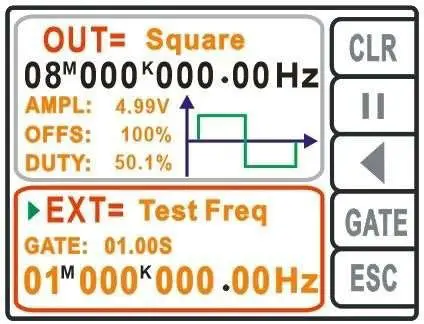
Figure 7-1
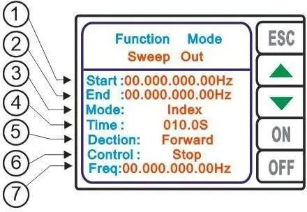
sweep function
Click the “Swp” function, enter the sweep setting interface, click the ![]() button to switch the adjustment parameters, and click the
button to switch the adjustment parameters, and click the ![]() button to change the adjustment parameter step value. Turn the knob to increase or decrease the parameter value.
button to change the adjustment parameter step value. Turn the knob to increase or decrease the parameter value.
- The starting value (Start) is the initial frequency of the sweep frequency;
- End value (End) sweep end frequency value;
- Mode sweep mode, there are two sweep modes: linear (Index) scan and logarithmic (Linear) scan;
- Time (Time) sweep time setting;
- Directions (Dection) sweep direction, there are three scanning directions, namely Forward scan, Reverse scan, Reciprocate scan;
- The sweep control (Control) shows the start and stop status of the sweep.
- The frequency (Freq) is displayed as the frequency sweep real-time frequency;
- Click the “esc” button to scan the control page and return to the main page.

1
Sweep start value 5 Sweep waveform 2 Sweep stop value 6 Sweep running status
3
Sweep mode 7 Scan real time frequency 4 Sweep time 8 air
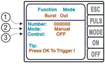
burst function
Click the “Brt” button to enter the function page, and click the FUNC button to enter the burst settings page as shown in Figure 9-1.
- Trigger the number of pulses (Number), click the “PULS” button to enter the burst number setting function, then click
 on the panel to change the step value of the parameter adjustment, and adjust the knob to change the size of the setting parameters.
 - Trigger mode (Mode), (Manual) manual trigger, after setting the parameters and starting the trigger function, click OK to enable the trigger function.(External) External trigger. After the parameter is set and the trigger function is activated, the burst function is enabled by an external signal.
- Control function (Control), click the “ON” button to open the burst function, click “OFF” off Closed burst function.
- Click the “esc” button to exit the burst control settings page and return to the main page.

system settings
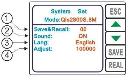
Click the “Sys” button to enter the system parameter setting page as shown in Figure 10-1.
- Parameter save and recall (Save & Real), the instrument has 10 sets of data storage locations, power-on default output 0 position data, click
 button to switch address bit parameters, click The button changes the variable adjustment parameter step value. Turn the knob to increase or decrease the address. Then click “save” to save the data or click “real” to call up the data for the corresponding location.
 - Sound: When the adjustment is ON, the beep is turned on; when it is “OFF”, the beep is turned off, and “SAVE” is clicked to save the setting state.
- Language: When the option is displayed as “English”, the operation interface is English. When the display is “Chinese”, the operation interface is Chinese. Click “SAVE” to save the setting status.
- Click the “esc” button to exit the parameter settings page and return to the main page.
Figure 101
Parameter save callout address bit 3 Language features 2 Beep sound enable 4 Frequency calibration
Contact information
Address: A110, Building 1, Entrepreneurship Center, 96 Ruida Road, Gaoxin District, Zhengzhou City.
Tel: 0371-56723980
mailbox: [email protected]
QQ: 2217881244


