![]() OPERATING
OPERATING
MANUAL
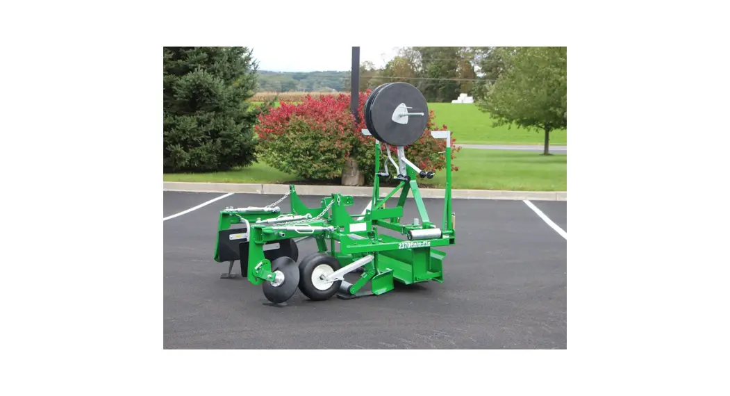
MODEL 2370
FLATBED PLASTIC MULCH LAYER
!! Safety First !!![]() Make sure you read and understand all the precautions.
Make sure you read and understand all the precautions.![]() Keep people away when lifting and lowering the machine.
Keep people away when lifting and lowering the machine.![]() Be careful when turning around; the machine is 6’ long.
Be careful when turning around; the machine is 6’ long.![]() Do not crawl under the machine when lifted.
Do not crawl under the machine when lifted.![]() Cover discs are sharp; stay clear.
Cover discs are sharp; stay clear.![]() Do not adjust the machine when it is moving.
Do not adjust the machine when it is moving.![]() Do not stand on the machine.
Do not stand on the machine.![]() The tractor operator is responsible for the extra worker(s) around the machine.
The tractor operator is responsible for the extra worker(s) around the machine.![]() Rain-Flo Irrigation is not responsible for accidents if any should occur.
Rain-Flo Irrigation is not responsible for accidents if any should occur.
Features
- The Model 2370 Flat Bed Mulch Layer will lay 3’, 4’ or 5’ Wide Plastic
- Extra Plastic Roll Carrier
- 16” Cover Disks with Dirt Shields
- Compact Machine; Category I 3-Point Hitch
- Lays Clear Plastic over Sweet Corn
- Adjustable Row Markers
- Adjustable Brake Tension on Plastic Roll Carriers
- Independent Disk & Press Wheels
- Quality Powder Coated Baked-On Paint
Options
- Optional Depth Wheels (For Sweet Corn)
- Optional Double or Single Drip Applicator
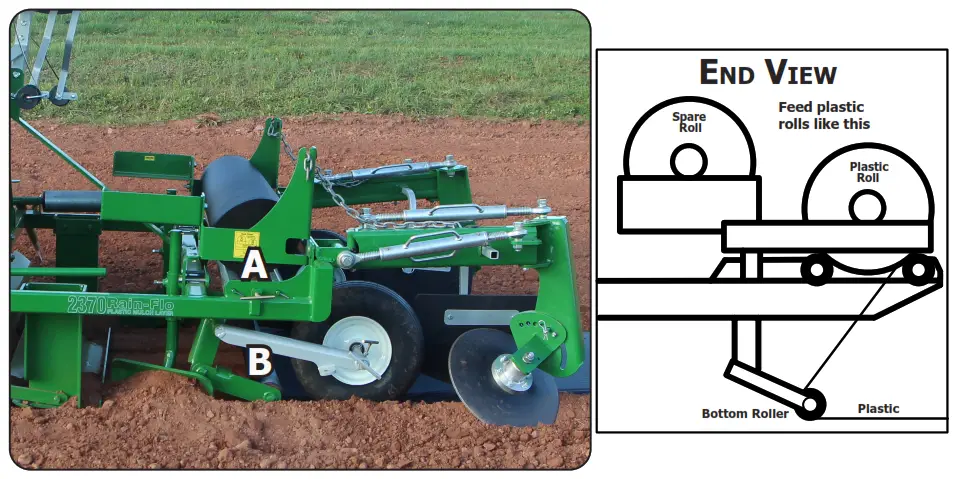
Installing Plastic Rolls
Place plastic rolls on top of rollers (A). Pull the end of the plastic down and underneath the bottom roller (B). Secure plastic and drip tape at end of the row.
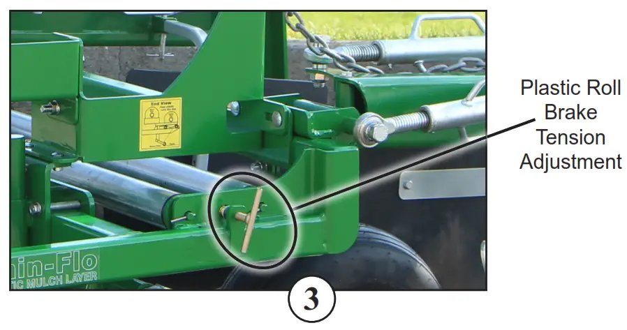
Adjusting Plastic Tension
Plastic rolls have a tension brake. Just a slight tension is needed. Note; Setting brake tension too tight on the plastic roll may affect the performance of the machine and can also use plastic to pull out from under press wheels.
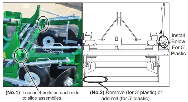
Changing Plastic Width
Model 2370 will lay 3’, 4’, or 5’ wide plastic.
- Loosen bolts (No. 1) and slide trench openers and roll holders so plastic roll fits between brackets. Adjust approximately 1½” wider than the plastic width to compensate for the roll’s core.
- Remove(for 3’) or add(for 5’) roller extensions (No. 2) to make desired
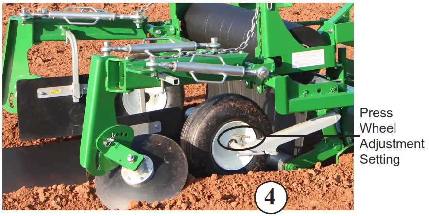
Press Wheel Adjustment
To stretch plastic more or less, turn axles to change the angle of the press wheels; make in or out adjustments as needed. Press wheels need to run at the bottom of the trench and not on the side. Use only high-quality plastic to avoid straight-line tears.
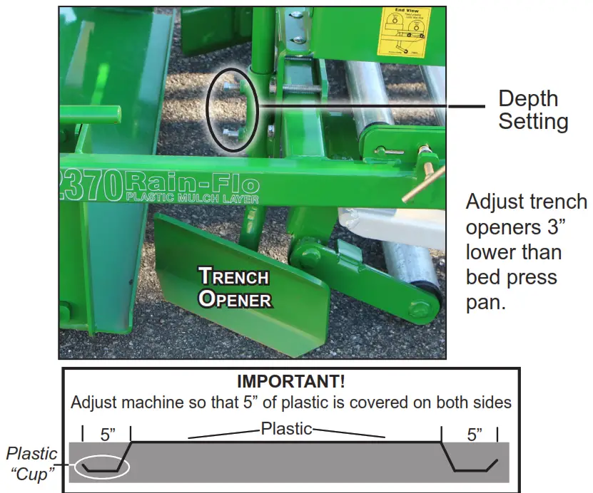
Trench Opener Adjustment
Trench openers are to cut a trench along the sides of the bed. This will give a ‘cup’ at the edge of the bed for the disk to cover the plastic.
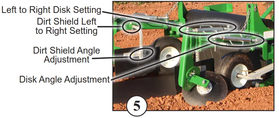
Cover Disk & Dirt Shield Adj.
Cover disks and dirt shields are marked right and left sides (standing at the back of the machine). Install shields as marked (with a ‘T’ handle towards the center of the bed.) Set is on a 45-degree angle then make in or out adjustments as needed.
For more coverage, bolt the disk on the opposite side of the upright shank and turn it around for a backward tilt.
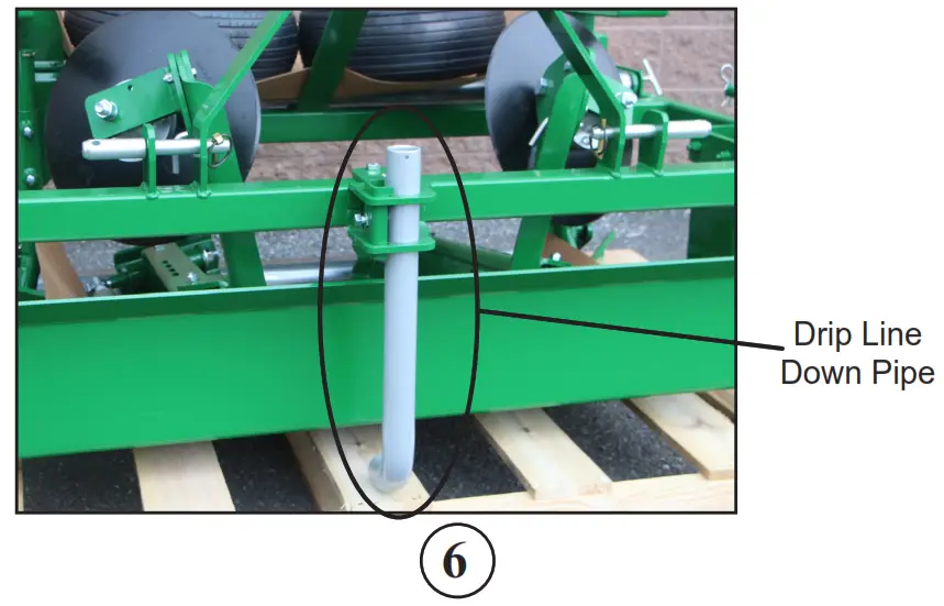
Drip Irrigation Roll Carrier
NOTICE:
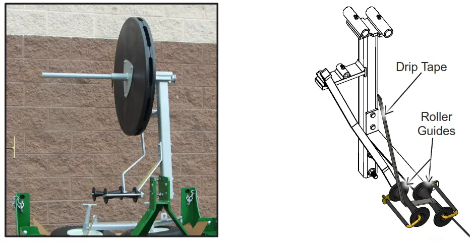
Slide drip rolls onto roll carrier rod so that drip emitter will be turned up toward plastic (for less clogging).
Make sure the drip roll is compressed firmly between plates for a positive braking effect.
Feed drip tape through the guide on the swing arm and through the second guide that’s bolted on the drip roll carrier frame. (See sketch above.)
To avoid damaging drip tape with the press pan, adjust the top of the downpipe about 1” to 2” below the plastic mulch. Cut off drip lines approximately one foot longer than the rows for connecting to the water supply. Keep dirt out of the drip tape by tying a knot at the end. The drip line can be tied to the back of the machine when transporting.
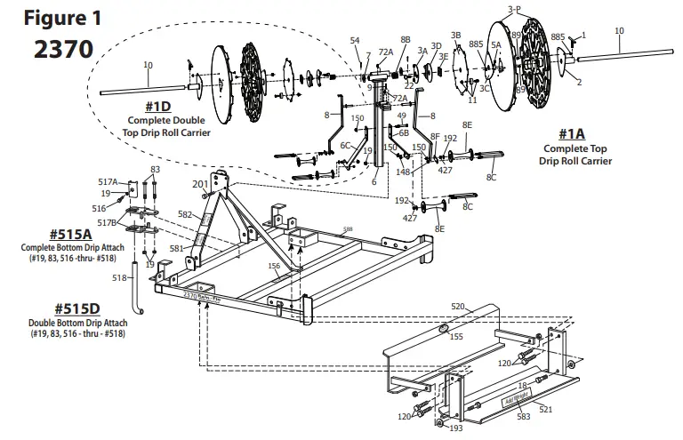 | 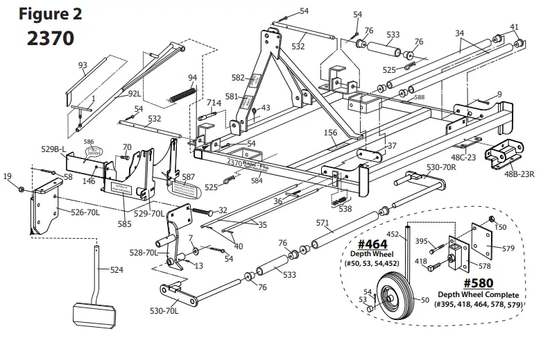 |
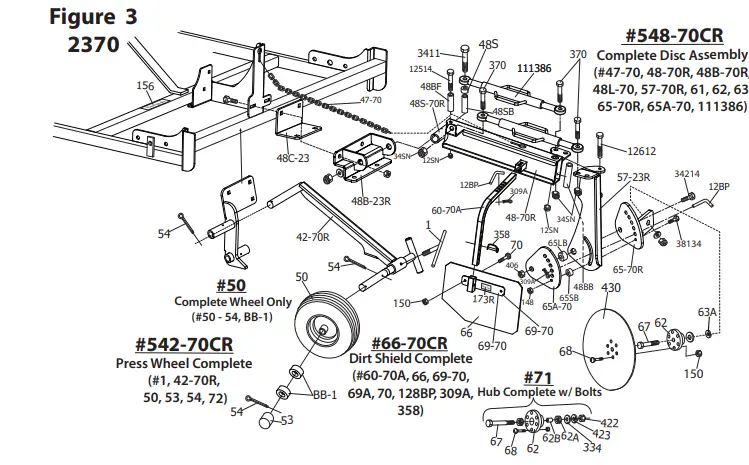
Model 2370 Flat Bed Layer
| Item ………………………….Description 1……………….(9) …………….Tee Handle 1A. ………………………………Complete Single Top Drip Roll Carrier 1D ……………………………….Complete Double Top Drip Roll Carrier 2………………………………….Roll Carrier Clamp 3A ……………………………….Drip Attach Adjustable Brake Tension Plate 3B ……………………………….Drip Attach Brake Plate 3C ……………………………….Drip Attach — Mounting for Brake Plate 3D ……………………………….Drip Attach Brake Tension Plate Rotation Stop 3E ……………………………….Drip Attach Teflon Brake Washer 3-P ……………(2) …………….Drip Roll Side Plates 5A ……………………………….⅜” x ½” Set Screw 6………………………………….Drip Roll Carrier Frame (Single or Double) 6B ……………………………….Drip Attach Arm to Guide Drip Tape 6C ……………………………….Drip Attach Arm to Guide Drip Tape [Double Drip] 7………………………………….1” SAE Washer 8………………………………….Swing Arm 8B ……………………………….Drip Attach Brake Tension Spring for 1” Rod 8C …………….(2) …………….Drip Attach Arm U-Bolt ⅜” x 2” x 6½” 8E …………….(2) …………….Drip Attach Arm Plastic Roller 8F ……………………………….Drip Attach Arm U-Bolt Plate Only 9……………….(7) …………….Cotter Pin [⅛”] 10………………………………..Drip Roll Shaft 11 ……………..(3) …………….Rubber Brake Assembly 12BP …………(4) …………….½” x 1½” Bent Pin 12SN ………..(2) …………….½” Zinc Stover Nut 13………………………………..Straight Grease Zerk 19……………….(8) ………………½” Flange Nut 20……………….(3) ………………5/16” x ¾” Carriage Bolt 22……………..(3) …………….5/16” x 1” Thumb Screw 32……………..(8) …………….½” x 4” Carriage Bolt 34. ……………(2) …………….Plastic Mulch Support Roll 35……………..(2) …………….Roll Holder Rod 36………………………………..Tension Tee Handle 37………………………………..Tension Plate 40……………..(2) …………….3/16” x 2” Roll Pin 41……………..(4) …………….UHMW Bushing 47-70. ……….(2) …………….Chain Shackle Complete 48-70L. ………………………..Rear Cover Disk Arm (Left Side) 48-70R…………………………Rear Cover Disk Arm (Right Side) 48B-23L. ……………………..Left Side Back Clamp For Disc Arm Swivel Bracket 48B-23R. ……………………..Right Side Back Clamp For Disc Arm Swivel Bracket 48C-23………(2) …………….Front Clamp For Disc Arm Swivel Bracket 48SB. ………..(2) …………….Bushing For Swivel Bracket; 1¼” OD x ¾” ID x 5.97” 50……………..(2) …………….Press Wheel Tire (#50 -thru- #54) 53……………..(2) …………….Hub Cap 54…………….(13) ……………Cotter Pin 57-23L. ………………………..Left Side Disk Hub Mounting Bracket 57-23R…………………………Right Side Disk Hub Mounting Bracket 58……………..(4) …………….Cotter Pin 60-70A. …….(2) …………….Dirt Shield Support Arm 62A ………….(4) …………….205KR3 Bearing 66. ……………(2) …………….Dirt Shield 66-70CL ………………………Left Side Dirt Shield Complete 66-70CR ………………………Right Side Dirt Shield Complete 67……………..(2) …………….¾” x 4½” Hub Center Bolt 68…………….(10) ……………⅜” x 1½” Button Socket Cap Bolt 69-70 ………..(2) …………….Dirt Shield Bracket 69A …………..(2) …………….Dirt Shield Flat Plate Bracket 70……………..(6) …………….⅜” x 1¼” Bolt 72……………..(3) …………….¼” x 90° Grease Zerk 72A ……………………………..¼” NFT 45° Grease Zerk 76……………..(6) …………….UHMW Bushing (Bottom Roller) 83……………..(2) …………….½” x 4¼” Bolt 89……………..(3) …………….¼” x ¾” Carriage Head Bolt 92L. …………………………….Left Side Row Marker 92R ……………………………..Right Side Row Marker 93……………..(2) …………….Row Marker Extension 94……………..(2) …………….Row Marker Spring 95……………..(2) …………….Row Marker Hinge Pin 120……………(4) …………….½” x 1½” Hex Bolt 133……………(2) …………….⅜” x 1½” Bolt 146…………..(10) ……………½” Hex Nut 148……………(2) …………….⅜” Nylon Lock Nut | Item ………………………….Description 150……………(2) …………….⅜” Flange Nut 155………………………………Rain-Flo Oval Logo Label 156………………………………Plastic Width Label 168………………………………Notice Label on Drip Attach 168A ……………………………“Turn Drippers Up For Less Clogging” Label 169………………………………Direction Arrow for Drip Attach 169A ……………………………Drip Attach Brake Adjustment Plate Label 172L ……………………………Left Side Standing in Back Label For Disk 172R ……………………………Right Side Standing in Back Label For Disk 173L ……………………………Left Side Standing in Back Label For Dirt Shield 173R …………………………..Right Side Standing in Back Label For Dirt Shield 185……………(2) …………….This Side-Up Label 192……………(4) …………….⅜” Flat Washer 193……………(4) …………….½” Flat Washer 195……………(3) …………….5/16” Flange Nut 201……………(2) …………….½” x 3¼” Bolt 309A …………(2) …………….Safety Pin for ½” Pin 334……………(2) …………….¾” SAE Washer 369……………(2) …………….½” x 2¾” Bolt 395……………(8) …………….⅜” x 2¾” Bolt 418……………(8) …………….⅝” x 1½” Set Screw 422……………(2) …………….¾” Hex Nut 423……………(2) …………….¾” Lock Washer 427…………..(30) ……………⅜” Nut 428…………..(30) ……………⅜” Lock Washer 430……………(2) …………….16” Disk Blade; 6 Bolt 452……………(2) …………….Tire, Axle and Stem 464……………(2) …………….Depth Wheel Complete [#452 -thru- 458] 515………………………………Bottom Drip Square Bar 515A ……………………………Complete Single Bottom Drip Attach 515D ……………………………Complete Double Bottom Drip Attach 516……………(4) …………….½” x 1½” Set Screw 517A ……………………………Bottom Drip Bolt Mounting 517B …………(2) …………….Bottom Drip Pipe Holder Bracket 518………………………………Bottom Drip Pipe 519……………(2) …………….CAT I Lifting Pin [Farmex] 520………………………………Leveling Pan 521………………………………Bed Press 524……………(2) …………….Trench Opener 525……………(2) …………….Safety Pin 526-70L ……………………….Left Side Trench Opener Bracket 526-70R……………………….Right Side Trench Opener Bracket 528-70L ……………………….Left Side Bottom Roll Holder Bracket 528-70R……………………….Right Side Bottom Roll Holder Bracket 529-70L ……………………….Left Side Plastic Roll Holder 529-70R……………………….Right Side Plastic Roll Holder 529B-L ………………………..Left Side Bolt-On Spare Roll Holder 529B-R ………………………..Right Side Bolt-On Spare Roll Holder 530-70L ……………………….Left Side Bottom Roller Holder 530-70R……………………….Right Side Bottom Roller Holder 532……………(2) …………….Row Marker Pins 533……………(2) …………….3’- 4’- 5’ Adjustment Roller 538………………………………Plastic Roll Brake Tension Spring & Washers 542-70CL …………………….Left Side Press Wheel Complete 542-70CR …………………….Right Side Press Wheel Complete 548-70CL …………………….Left Side Complete Disk Assembly 548-70CR …………………….Right Side Complete Disk Assembly 571………………………………Long Bottom Roller 578……………(2) …………….Depth Wheel Bracket with Tubing 579……………(2) …………….Depth Wheel Holder Plate 580……………(2) …………….Optional Depth Wheel Set Complete (2 Pcs) 581………………………………Serial Number Label 582……………………………… Firm Pressed Bed Label 583……………………………… Add More Weight Label 584……………(2) …………….Side Decal Label 585……………(2) …………….Plastic Roll End View Label 586……………(2) …………….Spare Roll Label 587……………(2) …………….Operating Instructions Label 588………………………………Plastic 5’ Width Roller Label 3411 ………….(2) …………….¾” x 11” Gr. 5 Zinc Hex Bolt 12514………..(2) …………….½” x 5¼” Gr. 5 Zinc Hex Bolt 12612………..(4) …………….½” x 6½” Gr. 5 Zinc Hex Bolt 34214………..(2) …………….¾” x 3¼” Gr. 5 Zinc Hex Bolt 38134………..(2) …………….⅜” x 1¾” Gr. 5 Zinc Hex Bolt 111386 ………(4) …………….13” Turnbuckle; 1⅛” ACME Thread BB-1 …………(4) …………….Sealed Ball Bearing |
Helpful Tips
- Adding weight will help make a firmer bed.
- Adjust the 3-point top link on the tractor to the level machine.
- Moisture in soil is important to build nice square beds.
- Stretching plastic in length and side to side will help plastic from blowing off. (See Page 3 & 4)
- Work up soil at least 6” deep.
- Periodically check for shallow spots in the bed; hollow beds will affect planting and hinder plant growth.
- Trench openers should not be set too deep; this may prevent the machine’s full weight from resting on the press pan and making a firm bed.
Warranty
All Rain-Flo mulch layers have a two-year warranty against defects in material and workmanship.
If any part is found defective, return the defective part with the Serial No. of the machine. If Rain-Flo finds it defective, it will be repaired or replaced at no charge.
Call Customer Service at (717) 445-3000.
TROUBLESHOOTING
- PROBLEM: The machine tends to drift sideways causing the press wheels to come off the plastic.
SOLUTION: *Use sway bars on tractor 3-point hitch. - PROBLEM: The cover disk not getting enough soil to cover the edge of the plastic.
SOLUTION: *Bolt disk on the opposite side of the upright shank and turn it around for a backward tilt. - PROBLEM: Plastic not staying under the press wheel.
SOLUTION: *Tension too tight on plastic roll carrier. - PROBLEM: Not firm beds and shallow spots in center.
SOLUTION: *Soil not tilled deep enough. *Add weight on bed press.
*Top links are too short.
~2021 Edition~
Rain-Flo Irrigation
(717) 445-3000


