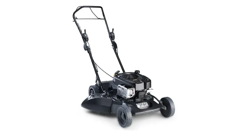
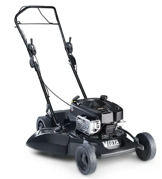
VICTA 2691588-B Mulchmaster 560 Lawn Mower 
Deck Group
Note:
Unless noted otherwise, use the standard torque specifications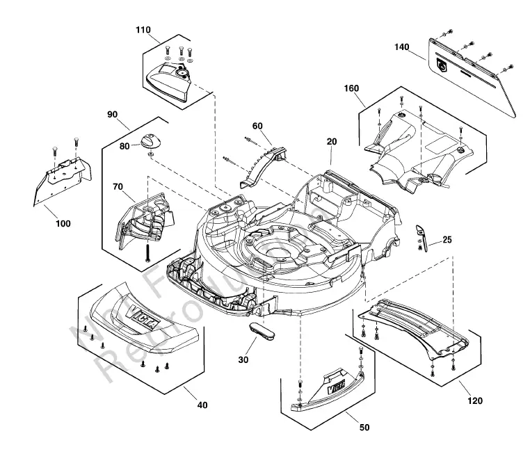
- 20 CH86859AW 1 CHASSIS, 560, Aztec Silver
- 25 —– 1 GEARBOX CURTAIN
- (Not a serviceable part)
- 30 CH85985A 1 PLUG, 4 Stroke Models Only
- 40 CH86939AW 1 BUMPER
- (Includes screws) 50 CH86897AW 1 WEAR PLATE PACK
- (Includes screws & washers)60 CH86861AW 1 SEGMENT
- 70 —– 1 MULCHING PLUG
- (Not a serviceable part) 80 CH86885AW 1 KNOB, Mulch Plug
- 90 CH86893AW 1 MULCH PLUG PACK
- (Includes Ref. Nos. 70 & 80)
- 100 CH87226A 1 DISCHARGE FLAP ASSEMBLY
- 110 CH86895AW 1 CHUTE PACK
- (Includes screws & washers) 120 CH86899AW 1 SKID PLATE PACK
- (Includes screws & washers)
- 140 CH88436A 1 REAR FLAP PACK, 560
- 160 CH86898AW 1 BELT COVER PACK
- (Includes screws & washers)
Engine & Blade Group
Note:
Unless noted otherwise, use the standard torque specifications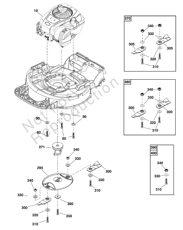
- REF NO PART NO QTY DESCRIPTION
- 10 123P32-0031-H5 1 ** ENGINE, Briggs & Stratton 850 Series
- 80 HA21320D 3 BOLT, Taptite, HW, 3/8 UNC x 30
- 90 HA22277D 3 WASHER, Engine Mounting
- 271 EE14476A 1 PULLEY & SLEEVE, Engine, 4-Stroke, 7/8″
- 290 CA09442G 1 BLADE DISC, Oval
- 300 —– 2 BLADE, Mower, Lo-Lift
- 305 CA09507B 2 BLADE, Hi Lift
- 310 —– 2 BOLT, Blade
- 320 CA09347A 2 WASHER, Blade Tension
- 330 HA25276BZ 2 WASHER, Belleville
- 340 CA09241D 2 NUT, Nylock, 3/8 UNC
- 350 EE14484B 1 BOLT, Flanged, Blade Disc
- 360 EN73054B 1 WASHER, Blade Disc
- 370 CA09276B 1 KIT, Blade & Bolt, Hi-Profile (1 Pair)
- (Includes Ref. No. 305, 310, 320, 330 & 340) 380 CA09584B 1 KIT, Blade & Bolt, Lo-Lift (1 Pair)
- (Includes Ref. No. 300, 310, 320, 330 & 340)
- 390 CA09277S 1 KIT, Hardware, Bolt, Washer, Nut (1 Pack)
- (Includes Ref. No. 310, 330 & 340) 400 CA09277P 1 KIT, Hardware, Blade, Washer, Nut , Bulk Pack (50 Pairs)
- (Includes Ref. No. 310, 330 & 340)
Note
Engine Style may vary from illustration. To verify your specific engine model, please reference the ID Tag located on your engine. See your local Briggs & Stratton distributor for parts and service.
Handles & Controls Group
Note:
Unless noted otherwise, use the standard torque specifications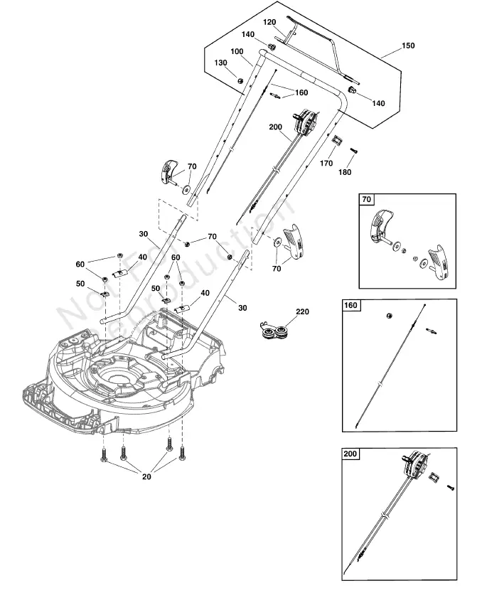
- REF NO PART NO QTY DESCRIPTION
- 20 HA20492D 4 BOLT, Hex Head, M8 x 65
- 30 CH87047GW 2 HANDLE, Lower, 560
- 40 CH80854GZ 2 PLATE, Saddle, Heavy
- 50 VV17130D 2 PLATE, Saddle
- 60 —– 4 NUT, Nylock, M8
- 70 CH88061P 1 WINGED LOCKING LEVER PACK V2
- (2 Sets Included, Kit includes Lever, Washer & Nut)
- 100 CH87048G 1 HANDLE, Upper, 560 S/P
- 120 CH88439A 1 BAIL ARM ASSEMBLY
- 130 HA24982D 1 NUT, Nylock, M6
- 140 CH86788A 2 SLEEVE, Bearing
- 150 80079136 1 UPPER HANDLE ASSEMBLY
- (Includes Ref. Nos. 100, 120, 130, 140 &160)
- 160 CH87424A 1 CABLE, Drive Clutch
- 170 —– 1 CLAMP, 22mm
- (Not a serviceable part)
- 80 —– 1 SCREW, M5 x 18
- (Not a serviceable part)
- 200 TC05064B 1 THROTTLE, Pro Control
- (Includes Ref. Nos. 170 & 180)
- 220 CH86896AW 1 TENSIONER MOUNT PACK 560
Wheels Group
Note:
Unless noted otherwise, use the standard torque specifications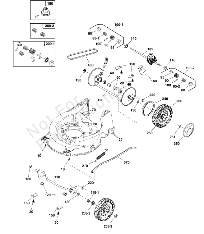
- 10 —– 4 SCREW, Hex Flange, M5 x 16 (Not a serviceable part.)
- 20 —– 6 SCREW, Pan Torx Trilobe, M6 x 19 (Not a serviceable part.)
- 30 —– 1 * SCREW, Pan Torx, Self Tap, ST4.2 x 16 (Not a serviceable part.)
- 40 CH84142A 2 RING, Sealing
- 50 CH84185U 2 BUSHING, Rear Axle
- 70 —– 1 * SCREW, Pan Torx, Self Tap, ST4.2 x 10 (Not a serviceable part.)
- 80 —– 2 SLEEVE, Fixed
- 85-1 —– 1 SPRING, RH, Black (Not a serviceable part.)
- 85-2 —– 1 SPRING, LH, Yellow (Not a serviceable part.)
- 90 —– 1 DRIVE GEAR(Not a serviceable part.)
- 95 —– 1 SLEEVE, Drive(Not a serviceable part.)
- 100 —– 2 PIN, Roll 1/8 x 3/4 SP(Not a serviceable part.)
- 110 CH86881AW 1 AXLE, Front
- 120 CH86276A 2 BUSHING, Front Axle
- 130 CH81445A 4 DUST SEAL
- 140 80084367 2 BEARING(Replaces Part Nos. HA25463A)
- 150 CH88275D 4 RETAINING PLATE, Axle
- 160 CH87420A 1 BRACKET, Gearbox 560
- 180 80080431 1 KIT, Variable Speed
- 185 CH87296A 1 GEARBOX GT-MC600
- 190 CH86938AW 1 AXLE, Rear
- 190-1 —– 1 GEAR, Over – Run Clutch, RH Black(Not a serviceable part.)
- 190-2 —– 1 GEAR, Over – Run Clutch, RH Yellow(Not a serviceable part.)
- 200-1 CH86816S 1 OVER RUN CLUTCH KIT
- 200-2 CH86823S 1 OVER RUN SPRING KIT
- 210 CH85943A 1 SPRING
- 220 HA25131D 2 E-CLIP
- 240 CH82847A 2 SEAL, Drive Wheel
- 250 CH86334A 4 WHEEL, Pro, 8″
- 260 CH86333A 2 WHEEL, Pro, 8″, REAR
- 250-1 —– 2 WASHER, Wheel, Front(Not a serviceable part.)
- 250-2 —– 2 BUSHING, Wheel, Front(Not a serviceable part.)
- 250-3 —– 2 WASHER, Wheel, Front
- 251 CH86298A 4 CAPTIVATED CLIP, Wheel
- 350 CH86112A 4 HUBCAP, Black
- 370 CH86862AW 1 CONLINK
- 400 80085135 1 V-BELT, 6736 Power Rated (Replaces Part Nos. CH85666A)
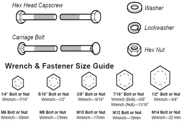
Hardware Identification & Torque Specifications
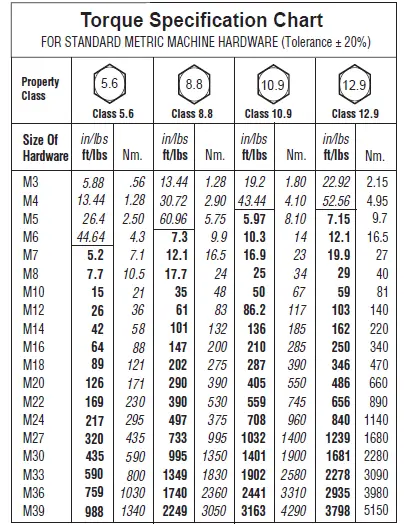
The guides and ruler furnished below are designed to help you select the appropriate hardware.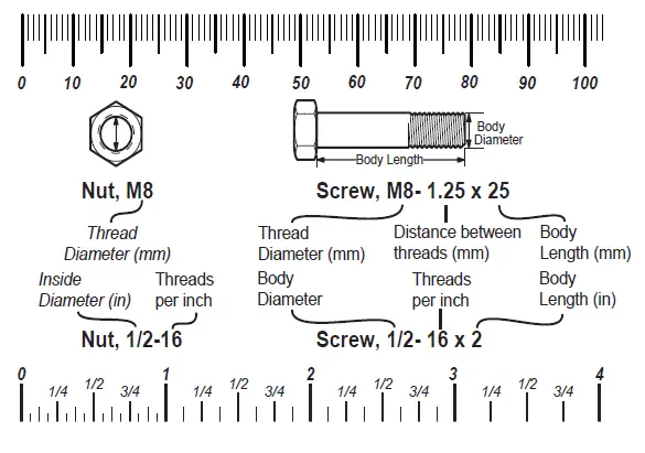
Standard Hardware Sizing
When a washer or nut is identified as 1/2” (M8), this is the Nominal size, meaning the inside diameter is 1/2 inch (8mm metric thread diameter); if a second number is present it represents the threads per inch (distance between threads). When bolt or capscrew is identified as 1/2 – 16 x 2” (M8 – 1.25 x 50), this means the Nominal size, or body diameter is 1/2 inch (8mm metric thread diameter), the second number,16, represents the threads per inch, (distance between threads). The final number is the body length of the bolt or screw, 2 inches (50mm).
| Torque Specification Chart FOR STANDARD MACHINE HARDWARE (Tolerance ± 20%) | ||||||
| Hardware Grade | No Marks
SAE Grade 2 |
SAE Grade 5 |
SAE Grade 8 | |||
| Size Of Hardware | in/lbs ft/lbs | Nm. | in/lbs ft/lbs | Nm. | in/lbs ft/lbs | Nm. |
| 8-32 | 19 | 2.1 | 30 | 3.4 | 41 | 4.6 |
| 8-36 | 20 | 2.3 | 31 | 3.5 | 43 | 4.9 |
| 10-24 | 27 | 3.1 | 43 | 4.9 | 60 | 6.8 |
| 10-32 | 31 | 3.5 | 49 | 5.5 | 68 | 7.7 |
| 1/4-20 | 66 | 7.6 | 8 | 10.9 | 12 | 16.3 |
| 1/4-28 | 76 | 8.6 | 10 | 13.6 | 14 | 19.0 |
| 5/16-18 | 11 | 15.0 | 17 | 23.1 | 25 | 34.0 |
| 5/16-24 | 12 | 16.3 | 19 | 25.8 | 29 | 34.0 |
| 3/8-16 | 20 | 27.2 | 30 | 40.8 | 45 | 61.2 |
| 3/8-24 | 23 | 31.3 | 35 | 47.6 | 50 | 68.0 |
| 7/16-14 | 30 | 40.8 | 50 | 68.0 | 70 | 95.2 |
| 7/16-20 | 35 | 47.6 | 55 | 74.8 | 80 | 108.8 |
| 1/2-13 | 50 | 68.0 | 75 | 102.0 | 110 | 149.6 |
| 1/2-20 | 55 | 74.8 | 90 | 122.4 | 120 | 163.2 |
| 9/16-12 | 65 | 88.4 | 110 | 149.6 | 150 | 204.0 |
| 9/16-18 | 75 | 102.0 | 120 | 163.2 | 170 | 231.2 |
| 5/8-11 | 90 | 122.4 | 150 | 204.0 | 220 | 299.2 |
| 5/8-18 | 100 | 136 | 180 | 244.8 | 240 | 326.4 |
| 3/4-10 | 160 | 217.6 | 260 | 353.6 | 386 | 525.0 |
| 3/4-16 | 180 | 244.8 | 300 | 408.0 | 420 | 571.2 |
| 7/8-9 | 140 | 190.4 | 400 | 544.0 | 600 | 816.0 |
| 7/8-14 | 155 | 210.8 | 440 | 598.4 | 660 | 897.6 |
| 1-8 | 220 | 299.2 | 580 | 788.8 | 900 | 1,244.0 |
| 1-12 | 240 | 326.4 | 640 | 870.4 | 1,000 | 1,360.0 |
| NOTES 1. These torque values are to be used for all hardware excluding: locknuts, self-tapping screws, thread forming screws, sheet metal screws and socket head setscrews. 2. Recommended seating torque values for locknuts: a. for prevailing torque locknuts – use 65% of grade 5 torques. b. for flange whizlock nuts and screws – use 135% of grade 5 torques. 3. Unless otherwise noted on assembly drawings, all torque values must meet this specification. | ||||||