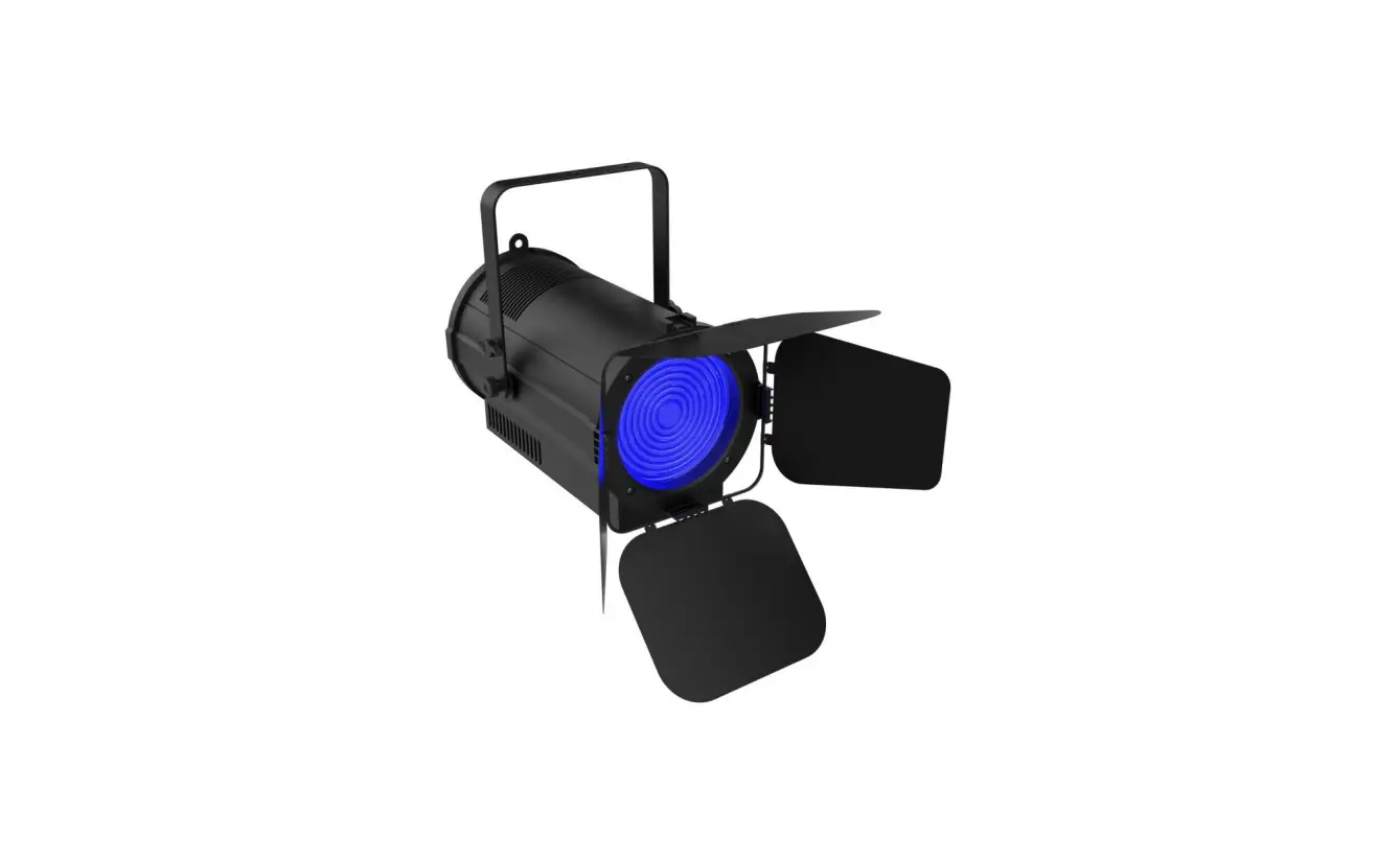
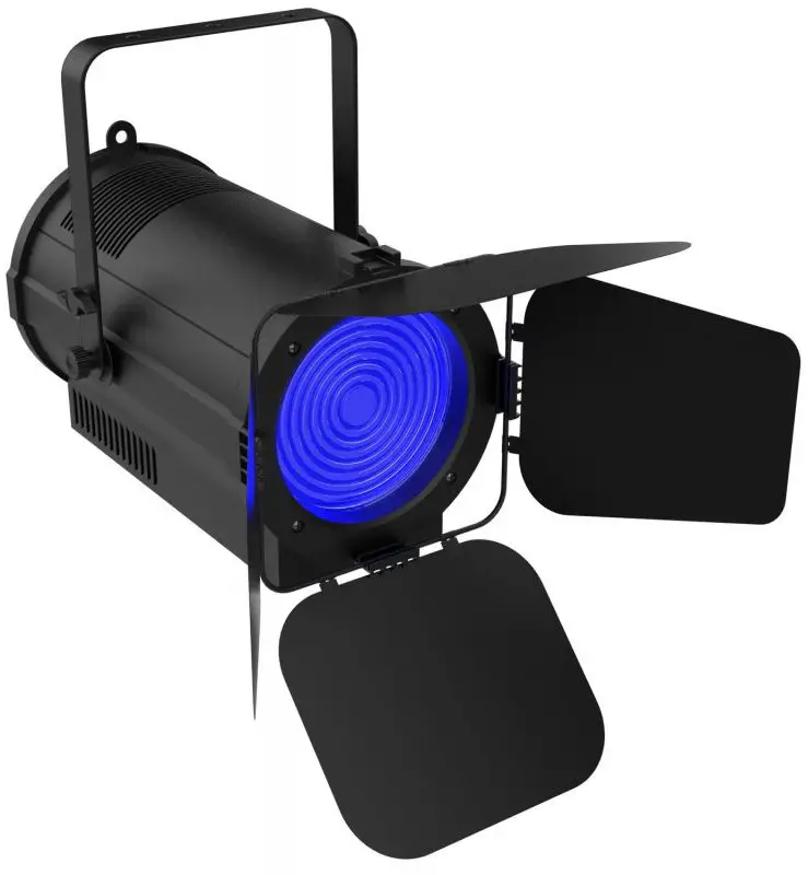
AUDIBAX Joliet 100 Zoom Lighting System

Caution!
- Be careful with your operations. With a dangerous voltage you can suffer a dangerous electric shock when touching the wires!
- Avoid looking directly into the light source!
- Wear protective glasses and other PPE (personal protective equipment) when working on or near the fixture.
- Always make sure you are connecting this product to the proper voltage in accordance with the specifications in this manual or on the product’s specification label. Make sure it is grounded when using it!
- Unplug mains lead before opening the housing!
- Make sure that the power cord is never crimped or damaged by sharp edges.
- Check the fixture and the power cord from time to time.
- Make sure to replace the fuse with another of the same type and rating.
- For your own safety, please read this user manual carefully before your initial start-up.
- Follow operating safety precautions and pay attention to warning signs methods and equipment on the user manual.
- Warning! This symbol indicates a hot surface. Certain parts of the housing can become hot during operation. After use, wait for a cool-down period of at least 10 minutes before handling or transporting the device.
- Indoor use only! To prevent risk of fire or shock, do not expose this product to rain or moisture. IP 20 rating.
- The ambient temperature must always be between -5° C and +45° C.
Every person involved with the installation, operation and maintenance of this device has to
- Be qualified
- Follow the instructions of this manual
- Consider this manual to be part of the total product
- Keep this manual for the entire service life of the product
- Pass this manual on to every further owner or user of the product
- Download the latest version of the user manual from the Internet
Introduction
- Thank you for having chosen Joliet 100 Zoom. You will see you acquired a powerful and versatile device.
- Unpack your item. Before your initial start-up, please make sure that there is no damage caused by transportation. Should there be any, consult your dealer and do not use the device.
Safety instructions
This device has left our premises in absolutely perfect condition. In order to maintain this condition and to ensure a safe operation, it is absolutely necessary for the user to follow the safety instructions and warning notes written in this user manual. Always disconnect from the mains, when the device is not in use or before cleaning it. Keep away children and amateurs from the device! There are no serviceable parts inside the device. Maintenance and service operations are only to be carried out by authorized dealers
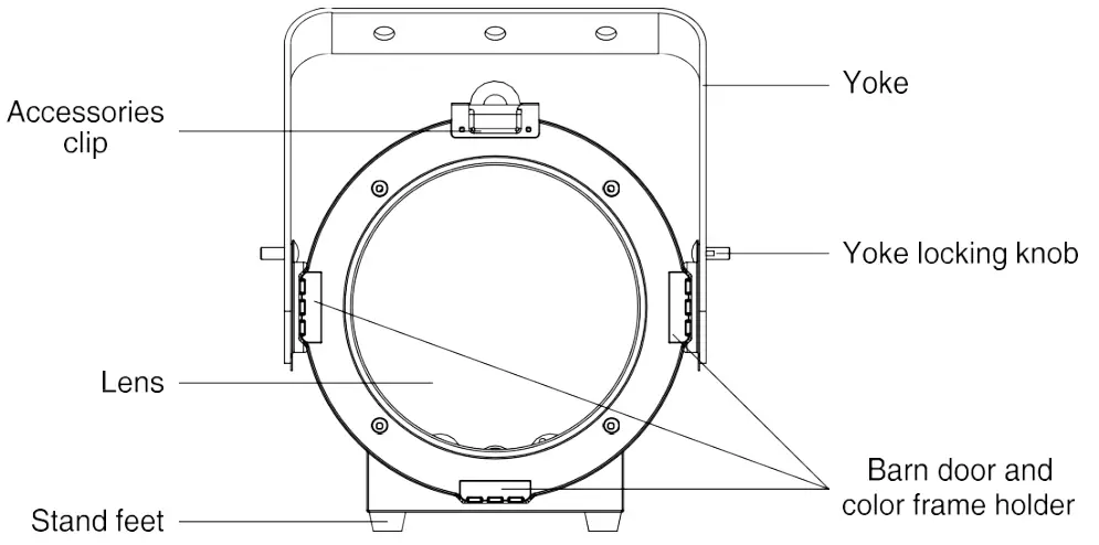
Overview
Installation
- Read ‘Safety information’ before installing the fixture.
- The fixture is designed for indoor use only and must be used in a dry location with adequate ventilation. Ensure that none of the fixture’s ventilation slots are blocked.
- Fasten the fixture to a secure structure or surface. Do not stand it on a surface or leave it where it can be moved or fall over. If you install the fixture in a location where it may cause injury or damage if it falls, secure it as directed in this user manual using a securely anchored safety cable that will hold the fixture if the primary fastening method fails.
- Fastening the fixture to a flat surface
- The fixture can be fastened to a hard, fixed, flat surface that is oriented at any angle. Ensure that the surface and all fasteners used can support at least 10 times the weight of all fixtures and equipment to be installed on it.
- Fasten the fixture securely. Do not stand it on a surface or leave it where it can be moved or fall over. If you install the fixture in a location where it may cause injury or damage if it falls, secure it as directed below with a securely anchored safety cable that will hold the fixture if the primary fastening method fails.
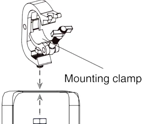
- Mounting the fixture on a truss
The fixture can be clamped to a truss or similar rigging structure in any orientation. When installing the fixture hanging vertically down, you can use an open-type clamp such as a G-clamp. When installing in any other orientation, you must use a half-coupler clamp that completely encircles the truss chord.
To clamp the fixture to a truss:
- Check that the rigging structure can support at least 10 times the weight of all fixtures and equipment to be installed on it.
- Block access under the work area.
- Fold the legs of the mounting bracket together and bolt a rigging clamp securely to the mounting bracket. The bolt used must be M10, grade 8.8 steel minimum. It must pass through both mounting bracket legs and be fastened with a self-locking nut.
- Working from a stable platform, hang the fixture with its clamp on the truss and fasten the clamp securely.
- Secure the fixture with a safety cable as directed below.

Securing with a safety cable
- Secure the fixture with a safety cable (or other secondary attachment) that is approved for the weight of the fixture so that the safety cable will hold the fixture if a primary attachment fails.
- Loop the safety cable through the eyebolt in the back of the fixture and around a secure anchoring point. Do not loop the safety cable around the fixture’s mounting bracket only, as this will leave the fixture unsecured if it separates from the bracket.
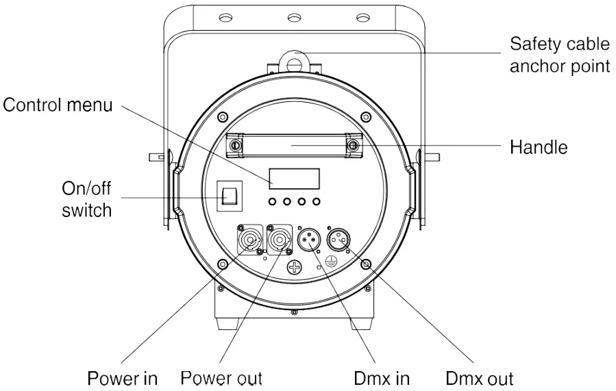
DMX-512 connection/connection between fixtures
Occupation of the XLR-connection:
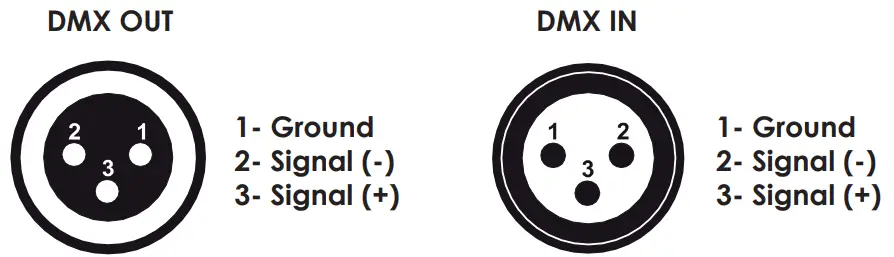
If you are using controllers with this occupation, you can connect the DMX-output of the controller directly with the DMX-input of the first fixture in the DMX-chain. If you wish to connect DMX-controllers with other XLR-outputs, you need to use adapter-cables.
Building a serial DMX-chain:
Connect the DMX-output of the first fixture in the DMX-chain with the DMX-input of the next fixture. Always connect one output with the input of the next fixture until all fixtures are connected.
DMX-512 connection with DMX terminator:
For installations where the DMX cable has to run a long distance or is in an electrically noisy environment, such as in a discotheque, it is recommended to use a DMX terminator. This helps in preventing corruption of the digital control signal by electrical noise. The DMX terminator is simply an XLR plug with a 120 resistor connected between pins 2 and 3, which is then plugged into the output XLR socket of the last fixture in the chain.
Caution: At the last fixture, the DMX-cable has to be terminated with a terminator. Solder a 120 Ω resistor between Signal (–) and Signal (+) into a 3-pin XLR-plug and plug it in the DMX-output of the last fixture.
Power connection
Power Requirements
The Joliet 100 Zoom luminaire operates on 100 to 240 volts AC (+/- 10%, auto-ranging). The luminaire contains an auto-ranging power supply.
Power linking between fixtures:
The fixture with powercon in and out socket. Connect the power out to the power in socket in the next fixture till all are connected.
Caution: maximum power linking – 8 units
Connection with the mains:
Connect the device to the mains with the enclosed power supply cable.
The occupation of the connection cables as below:
| Cable color | Connection | International |
| Brown | Live | L |
| Blue | Neutral | N |
| Yellow/green | Earth(Ground) |
Operation
The Joliet 100 zoom can operate different modes. In each mode you can run the fixture as a standalone fixture or in a master/slave configuration. This next section will detail the differences in the operating modes.
| MENU | SUB MENU | OPERATION |
| Addr | d001-d512 | RDM/DMX address |
| CHnL | 2CH | Channel mode |
| 3CH | ||
| 4CH | ||
| 5CH | ||
| Strb | S.01-s.20 | Strobe with speed increasing |
| uL– | u.000-u.255 | Dimmer |
| FL– | F.000-255 | Zoom function |
|
nodE | nod.0 | Dimmer speed 0 (no delay) |
| nod.1 | Dimmer speed 1 | |
| nod.2 | Dimmer speed 2 | |
| nod.3 | Dimmer speed 3 | |
| nod.4 | Dimmer speed 4 (slowest speed) | |
| Id | Id.01-Id.66 | ID address setting |
| tEnP | -25~100 | Fixture temperature |
| UErn | Firmware version | |
| rSEt | yes/no | Reset |
| pnnF | (1.2~24.0)F | PWM refresh rate adjustment(KHz) |
Addressing
- All fixtures should be given a DMX starting address when using a DMX signal, so that the correct fixture responds to the correct control signals. This digital starting address is the channel number from which the fixture starts to listen to the digital control information sent out from the DMX controller. The allocation of this starting address is achieved by setting the correct number on the display located on the base of the device.
- You can set the same starting address for all fixtures or a group of fixtures, or make different address for each fixture individually
- If you set the same address, all the units will start to listen to the same control signal from the same channel number. In other words, changing the settings of one channel will affect all the fixtures simultaneously.
- If you set a different address, each unit will start to listen to the channel number you have set, based on the quantity of control channels of the unit. That means changing the settings of one channel will affect only the selected fixture.
- In the case of the Joliet 100 Zoom, which is 2/3/4/5 channels fixture. If you set, for example, the ad- dress in the 2 channel mode to channel 3, the device will use the channel 3 to 4 for control.
Universal DMX Control
This function allows you to use a universal DMX-512 controller to control the dimmer and strobe. A DMX controller allows you to create unique programs tailored to your individual needs.
RDM control
- The Joliet 100 Zoom can communicate using RDM (Remote Device Management) in accordance with ESTA’s American National Standard E1.20-2006: Entertainment Technology RDM Remote Device Management over DMX512 Networks.
- RDM is a bi-directional communications protocol for use in DMX512 control systems; it is the open standard for DMX512 device configuration and status monitoring.
- The RDM protocol allows data packets to be inserted into a DMX512 data stream without affecting existing non-RDM equipment. It allows a console or dedicated RDM controller to send commands to and receive messages from specific fixtures.
- With RDM function, you can set the DMX address of your fixtures remotely. This is especially useful when the device is installed in a remote area.
- Each Joliet 100 Zoom has a factory set RDM UID (unique identification number).
DMX Protocol
| 2 Channels Mode | Function | Function Control |
| CH1 | Dimmer | 000-255: 0-100% dimmer |
| CH2 | Zoom | 000-255: zoom function |
| 3 Channels Mode | Function | Function Control |
| CH1 | Dimmer | 000-255: 0-100% dimmer |
| CH2 | Strobe | 000-255: strobe with speed increasing |
| CH3 | Zoom | 000-255: zoom function |
| 4 Channels Mode | Function | Function Control |
| CH1 | Dimmer | 000-255: 0-100% dimmer |
| CH2 | Strobe | 000-255: strobe with speed increasing |
| CH3 | Zoom | 000-255: zoom function |
|
CH4 |
Dimmer mode | 000-005: Menu setting |
| 006-055: Dimmer speed 0 (no delay) | ||
| 056-105: Dimmer speed 1 | ||
| 106-155: Dimmer speed 2 | ||
| 156-205: Dimmer speed 3 | ||
| 206-255: Dimmer speed 4 (slowest speed) |
| 5 Channels Mode | Function | Function Control |
| CH1 | Dimmer | 000-255: 0-100% dimmer |
| CH2 | Strobe | 000-255: strobe with speed increasing |
| CH3 | Zoom | 000-255:zoom function |
|
CH4 |
Dimmer mode | 000-005: Menu setting |
| 006-055: Dimmer speed 0 (no delay) | ||
| 056-105: Dimmer speed 1 | ||
| 106-155: Dimmer speed 2 | ||
| 156-205: Dimmer speed 3 | ||
| 206-255: Dimmer speed 4 (slowest speed) | ||
|
CH5 |
ID address setting | 000-009: ID1-ID66 |
| 010-019: ID1 | ||
| 020-029: ID2 | ||
| 030-039: ID3 | ||
| … | ||
| 200-209: ID20 | ||
| 210: ID21 | ||
| 211: ID22 | ||
| … | ||
| 255: ID66 |
ID address selection
Each independent DMX address can have up to 66 ID addressed fixtures. An ID address of 0 will activate all ID address locations.
CH5 is used to select the target ID address.
| DMX value | Function |
| 000-009 | ID1-ID66 |
| 010-019 | ID1 |
| 020-029 | ID2 |
| 030-039 | ID3 |
| 040-049 | ID4 |
| 050-059 | ID5 |
| 060-069 | ID6 |
| 070-079 | ID7 |
| 080-089 | ID8 |
| 090-099 | ID9 |
| 100-109 | ID10 |
| 110-119 | ID11 |
| 120-129 | ID12 |
| 130-139 | ID13 |
| 140-149 | ID14 |
| 150-159 | ID15 |
| 160-169 | ID16 |
| 170-179 | ID17 |
| 180-189 | ID18 |
| 190-199 | ID19 |
| 200-209 | ID20 |
| 210 | ID21 |
| 211 | ID22 |
| DMX value | Function |
| 212 | ID23 |
| 213 | ID24 |
| 214 | ID25 |
| 215 | ID26 |
| 216 | ID27 |
| 217 | ID28 |
| 218 | ID29 |
| 219 | ID30 |
| 220 | ID31 |
| 221 | ID32 |
| 222 | ID33 |
| 223 | ID34 |
| 224 | ID35 |
| 225 | ID36 |
| 226 | ID37 |
| 227 | ID38 |
| 228 | ID39 |
| 229 | ID40 |
| 230 | ID41 |
| 231 | ID42 |
| 232 | ID43 |
| 233 | ID44 |
| 234 | ID45 |
| DMX value | Function |
| 235 | ID46 |
| 236 | ID47 |
| 237 | ID48 |
| 238 | ID49 |
| 239 | ID50 |
| 240 | ID51 |
| 241 | ID52 |
| 242 | ID53 |
| 243 | ID54 |
| 244 | ID55 |
| 245 | ID56 |
| 246 | ID57 |
| 247 | ID58 |
| 248 | ID59 |
| 249 | ID60 |
| 250 | ID61 |
| 251 | ID62 |
| 252 | ID63 |
| 253 | ID64 |
| 254 | ID65 |
| 255 | ID66 |
Fixture Cleaning
Due to fog residue, smoke, and dust cleaning the internal and external optical lenses and mirror should be carried out periodically to optimize light output. Cleaning frequency depends on the environment in which the fixture operates (I.e. smoke, fog residue, dust, dew). In heavy club use we recommend cleaning on a monthly basis. Periodic cleaning will ensure longevity, and crisp output.
To clean the fixture:
- Disconnect the fixture from power and allow it to cool for at least 10 minutes.
- Vacuum or gently blow away dust and loose particles from the outside of the fixture with low-pressure compressed air.
- Clean the surfaces by wiping gently with a soft, clean lint-free cloth moistened with a weak detergent solution. Do not rub glass surfaces hard: lift particles off with a soft repeated press. Dry with a soft, clean, lint-free cloth or low-pressure compressed air. Remove stuck particles with an unscented tissue or cotton swab moistened with glass cleaner or distilled water.
- Check that the fixture is dry before reapplying power.
Fuse Replacement
This fuse is located in a fuseholder next to the MAINS OUT socket on the connections panel.
To replace a fuse:
- Disconnect the fixture from power and allow it to cool for at least 10 minutes.
- Unscrew the cap of the fuseholder and remove the fuse. Replace with a fuse of the same size and rating only.
- Reinstall the fuseholder cap before reapplying power.
Troubleshooting
Listed below are a few common problems that you may encounter, with solutions.
The fixture does not work, no light
- Check the connection of power and main fuse. Be sure the external fuse has not blown.
- Measure the mains voltage on the main connector.
Technical specifications
| Model | Joliet 100 Zoom |
| Power supply: | AC100-240V, 50/60Hz |
| Light source: | 100W COB LED |
| Color temperature: | 3200K/5600K optional |
| Color Rendition: | CRI 97, R9≥90, TLCI up to 98 |
| Zoom range: | 25°-65° motorized |
| Power connection: | PowerCON in&out |
| Maximum power linking: | 8 units |
| Signal connection: | 3-pin XLR in&out(5-pin optional) |
| DMX channels: | 2/3/4/5 |
| Control mode: | RDM, DMX, Rotary, Master-slave |
| Housing: | Color black, Aluminum |
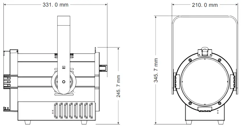
| Size(barn door excluded): | 331 x 210 x 345.7mm(13 x 8.3 x 13.6in) |
| Package(carton): | 448 x 338 x 400mm(17.6 x 13.3 x 15.7in) |
| N.W.: | 6.6kg(14.5lb) |
| Enviroment: | IP20 |
DIMENSION