
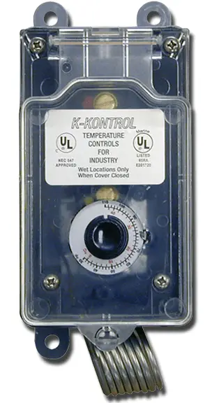
K-KONTROL Line Voltage Thermostats
Please read and save these instructions. Read carefully before attempting to assemble, install, operate or maintain the product described. Protect yourself and others by observing all safety information. Failure to comply with instructions could result in personal injury and/or property damage!Retain instructions for future reference.
Description
These Line Voltage Thermostats are designed for reliable use in heating, ventilating, and refrigeration applications. A variety of models offer a broad temperature range between -30° and +120°F (-34° and +49°C) allowing for a wide range of heating, ventilating, and refrigeration applications.
K Kontrol Line Voltage Thermostats are designed to directly control heating or cooling loads. See the ratings on the thermostat nameplate.
K Kontrol Thermostats are designed to be rain tight and dust tight and are rated for use in agricultural buildings.
See the full range of K Kontrol Thermostats at kkontrol.com
General Safety Information
WARNING
Disconnect all power before installing or servicing this product. If the power disconnect is out of view, lock it in the open position and tag it to prevent unexpected restarting of power. Failure to do so could result in fatal electric shock.
- Special attention must be given to any grounding information on this product and to other equipment associated with its installation and use. To ensure a proper ground, the grounding means must be checked by a qualified electrician.
- Be certain that the electrical ratings of the thermostat conform to the power source and the load(s) being controlled. Loads that exceed the rating of the thermostat should be handled with a suitable rated relay or motor starter.
WARNING: Do not depend upon the thermostat as the sole means of disconnecting power when installing or servicing the product it is controlling. Always disconnect power at the main circuit breaker as described above. Failure to do so could result in fatal electric shock. - This thermostat (not including thermostats with a cord) is intended ONLY for permanent installation in accordance with the United States National Electrical Code (NEC), all applicable local codes and ordinances, and all sections of this manual. All wiring should be done by a qualified electrician, using copper wire only.
WARNING
These thermostats are intended for general heating, ventilating, and refrigeration ONLY. They must NOT be used in potentially dangerous locations such as flammable, explosive, chemical laden areas or in wet atmospheres.
These thermostats are designed for use as operating controls only. Where an operating control failure would result in personal injury and/or loss of property, it is the responsibility of the installer to add devices (safety, limit controls) or systems (supervisory alarm systems) that protect against, or warn of control failure.
In cases where personal injury or property damage may result from malfunction of the thermostat, a backup system must be used. Where critical or high value products are maintained, an approved temperature limit should be wired in series with this thermostat. In less critical applications, a second thermostat with alarm contacts may be used for redundancy.
Installation
LOCATION
Mount this product 5 to 6 feet (1.5 to 1.8 m) above the floor so it will be exposed to the average temperature of the controlled space. Do not mount control where it could be affected by unusual heat or cold such as in sunlight or beside equip ment. Avoid locations near a door, window or other opening. Do not mount on an outside wall. When the thermostat is mounted with coil pointed down, it is protected from falling objects, dirt, and debris.
MOUNTING – FIXED INSTALLATIONS
Four mounting holes for fixed installa -tions are found in the back of the case. On rough surfaces use the top mounting holes only. When mounting this control on uneven surfaces, when all four mounting screws are tightened, the housing may deform enough to affect the thermostat calibration and operation.
CAUTION: Do not dent or deform the sensor coil of this control. A dent or deformation will change the calibration and cause the control to cycle at a temperature lower than the knob setting.
MOUNTING – THERMOSTATS WHICH ARE SUPPLIED WITH A CORD AND SERIES PLUG
To reduce the risk of electric shock, this product has a grounding type plug that has a third (grounding) pin. This plug will only fit into a grounding type power outlet. If the plug does not fit into the outlet, contact a qualified electrician to install the proper outlet. Do not change the plug in any way.
Certain thermostats are supplied with a cord and series plug for easy connection to a 120V AC grounded receptacle. Hang the thermostat near a 120V three prong receptacle with a ground pin using the hanging wire included in the package. Plug the male prongs into the receptacle and then plug the controlled equipment into the female part of the plug. For best results do not locate the thermostat near an exterior wall or window and away from the discharge of the equipment.
If an extension cord is required use only one with a grounded 3 prong plug and 14 gage wire.
CAUTION: Do not allow the thermostat to be placed on the floor where it could come in contact with moisture, or be stepped on. Doing so could result in a fatal electric shock.
RAINTIGHT THERMOSTAT INSTALLATION
These thermostats are designed for use in wet or humid environments. To ensure water tightness, a UL listed cord seal or conduit hub marked “4X” should be tightened onto the conduit before installing in the enclosure. A drip loop must be used to prevent moisture from entering the thermostat housing. Make certain that all connectors are securely tightened.
MOUNTING – EXTENDABLE BULB THERMOSTAT INSTALLATION
These thermostat models have asensor bulb attached to the end of an extendable capillary tube. The sensor bulb on these units is designed to monitor temperature remotely from the control module. When extending the sensor, avoid bending or kinking the extendable capillary tube, as this will affect the accuracy of the unit. Make sure that any excess tubing is coiled beneath the thermostat control module.
The control module should be located in a convenient place within a distance easily reached by the thermostats’ extendable sensing bulb. Care should be taken to install the sensing bulb where it will sense the average ambient temperature of the area to be controlled.
For remote room installations, mount the sensing bulb in a location where the ambient air can easily circulate around the sensing bulb. For cold room installations, the sensing bulb may also be mounted on the suction side of a refrigerant line, and secured in position.
For duct installations, position the sensing bulb where it is in the primary air stream and avoid mounting the sensing bulb close to hot pipes, cooling coils, or other areas which may cause an inaccurate reading.
For tank installations, the sensing bulb can be inserted directly into the tank fluid. Place the sensing bulb in a location where the liquid will circulate around the sensing bulb and where it is not affected by extraneous temperatures.
WIRING
IMPORTANT: All wiring should be done in accordance with applicable codes, ordinances and regulations. Use a disconnect device and overload protection to assure safe installation complying with local and national codes. Figures 1, 2 and 3 illus trate typical wiring for control
of heating, cooling, refrigeration, and combination heating/cooling control systems (use copper conductors only).
NOTE: Letters R, B and Y (red, blue and yellow) refer to color of paint dots near terminals, or wire colors for some models (see Figure A).
For some models, the wiring terminals are labeled as follows:
P1 for Power Supply
1 for Heat Load
2 for Cooling Load
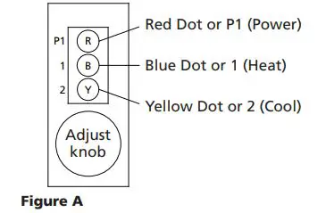
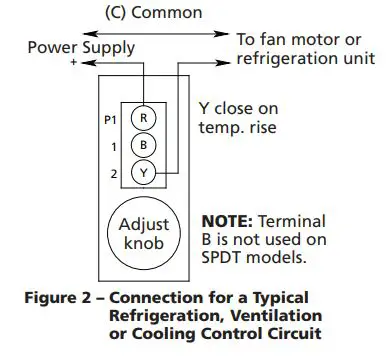
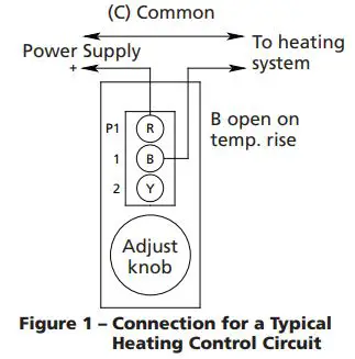
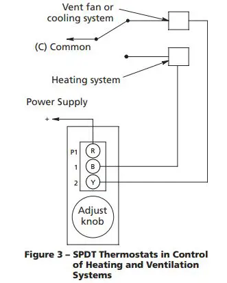
Figure 4 shows wiring for controlling a two-speed ventilating fan. When the control element reaches the knob settings, the low temperature switch starts the fan on low speed. If the ambient temperature continues to rise, the high-temperature switch supplies power to the high-speed motor winding.
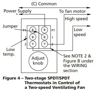 Figure 5 shows a typical SPDT/SPDT connection for a two-speed fan appli cation. The damper motor will be ener gized when the temperature reaches the knob setting. If the temperature continues to rise, the fan motor will be energized by the high temperature switch.
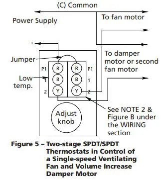
SPDT/SPDT units can also be used to control a combination heating and ventilating or cooling system, as shown in Figure 6. A temperature increase to the knob setting will turn off the heating system when the Red-Blue contacts of the low temperature switch break. An increase in tempera ture of about 3ºF will turn on the fan or cooling system through the Red dot, Yellow dot contacts of the high temperature switch.
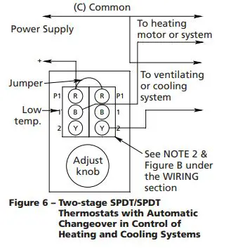
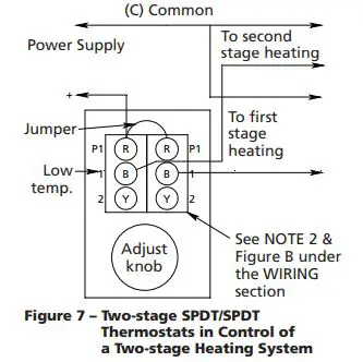
Figure 7 illustrates typical wiring for SPDT/SPDT units for control of two heating stages. As the ambient temperature decreases to the knob setting, the high temperature switch will make Red-Brown wire or Blue dot, Yellow dot contact, turning on the first stage of heating. If the temperature continues to drop (about 3ºF) the low temperature switch will make Red-Blue contact, turning on the second stage of heating.
CHECKOUT PROCEDURE
Before leaving the installation, a complete operating cycle should be observed
to ensure that all components are functioning properly. Check for correct operation in the following sequence:
- When thermostats are connected to Refrigeration, Ventilating, or Cooling Systems: Turn knob clockwise to a setting above ambient temperature. Fan or Cooling System should be off. When knob is turned counterclockwise (to lower temperature setting), the fan or cooling system should turn on approximately at the knob setting.

- When thermostats are connected to a Heating device or system: Turn knob clockwise above the ambient temperature; the heating unit should be on. When knob is turned counter -clockwise (to lower temperature setting), the heating unit should turn off approximately at the knob setting.
- Thermostats with SPDT/SPDT 2 Stage switching: If connection is similar to Figure 4, fan should start at approximately ambient temperature and should change to high speed, as the knob is turned counterclockwise to a lower temperature setting. If wiring is similar to Figure 5, the damper should open as the knob is turned counterclockwise (to lower temperature setting). The devices should act in reverse sequence when the knob is turned clockwise.
Operation
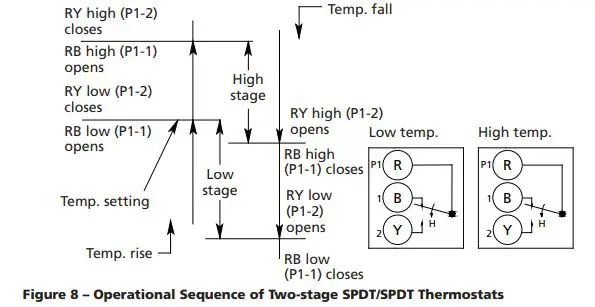
Figure 8 illustrates the operation of thermostats with SPDT/SPDT 2 Stage switching. On a temperature increase to the knob setting, the circuit between R (P1) and Y (2) of the low stage switch (RYL) closes. Simultaneously the circuit between R (P1) and B (1) (RBL) opens.
On a further increase in temperature the high stage switch operates and closes (RYH) while simultaneously opening
(RBH). The reverse sequencing takes place with a decrease in temperature.
NOTE: No replacement parts available. Do not attempt any field repair.
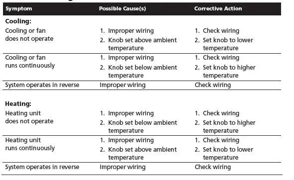
Troubleshooting Chart
LIMITED WARRANTY
K KONTROL ONE-YEAR LIMITED WARRANTY. K KONTROL™ LINE VOLTAGE THERMOSTATS, MODELS COVERED IN THIS MANUAL, ARE WARRANTED BY K KONTROL TO THE ORIGINAL USER AGAINST DEFECTS IN WORKMANSHIP OR MATERIALS UNDER NORMAL USE FOR ONE YEAR AFTER DATE OF PURCHASE. ANY PART WHICH IS DETERMINED TO BE DEFECTIVE IN MATERIAL OR WORKMANSHIP AND RETURNED TO AN AUTHORIZED SERVICE LOCATION, AS K KONTROL DESIGNATES, SHIPPING COSTS PREPAID, WILL BE, AS THE EXCLUSIVE REMEDY, REPAIRED OR REPLACED AT K KONTROL’S OPTION. FOR LIMITED WARRANTY CLAIM PROCEDURES, SEE
“PROMPT DISPOSITION” BELOW. THIS LIMITED WARRANTY GIVES PURCHASERS SPECIFIC LEGAL RIGHTS WHICH VARY FROM JURISDICTION TO JURISDICTION.
LIMITATION OF LIABILITY. TO THE EXTENT ALLOWABLE UNDER APPLICABLE LAW, K KONTROL’S LIABILITY FOR CONSEQUENTIAL AND INCIDENTAL DAMAGES IS EXPRESSLY DISCLAIMED. K KONTROL’S LIABILITY IN ALL EVENTS IS LIMITED TO AND SHALL NOT EXCEED THE PURCHASE PRICE PAID.
WARRANTY DISCLAIMER. A DILIGENT EFFORT HAS BEEN MADE TO PROVIDE PRODUCT INFORMATION AND ILLUSTRATE THE PRODUCTS IN THIS LITERATURE ACCURATELY; HOWEVER, SUCH INFORMATION AND ILLUSTRATIONS ARE FOR THE SOLE PURPOSE OF IDENTIFICATION, AND DO NOT EXPRESS OR IMPLY A WARRANTY THAT THE PRODUCTS ARE MERCHANTABLE,
OR FIT FOR A PARTICULAR PURPOSE, OR THAT THE PRODUCTS WILL NECESSARILY CONFORM
TO THE ILLUSTRATIONS OR DESCRIPTIONS. EXCEPT AS PROVIDED BELOW, NO WARRANTY OR AFFIRMATION OF FACT, EXPRESSED OR IMPLIED, OTHER THAN AS STATED IN THE “LIMITED WARRANTY” ABOVE IS MADE OR AUTHORIZED BY K KONTROL.
Technical Advice and Recommendations, Disclaimer. Notwithstanding any past practice or dealings or trade custom, sales shall not include the furnishing of technical advice or assistance or system design. K Kontrol assumes no obligations or liability on account of any unauthorized recommendations, opinions or advice as to the choice, installation or use of products.
Product Suitability. Many jurisdictions have codes and regulations governing sales, construction, installation, and/or use of products for certain purposes, which may vary from those in neighboring areas. While attempts are made to assure that K Kontrol products comply with such codes, K Kontrol cannot guarantee compliance, and cannot be responsible for how the product is installed or used. Before purchase and use of a product, review the product applications, and all applicable national and local codes and regulations, and be sure that the product, installation, and use will comply with them.
Certain aspects of disclaimers are not applicable to consumer products; e.g., (a) some jurisdictions do not allow the exclusion or limitation of incidental or consequential damages, so the above limitation or exclusion may not apply to you; (b) also, some jurisdictions do not allow a limitation on how long an implied warranty lasts, consequently the above limitation may not apply
to you; and (c) by law, during the period of this Limited Warranty, any implied warranties of implied merchantability or fitness for a particular purpose applicable to consumer products purchased by consumers, may not be excluded or otherwise disclaimed.
Prompt Disposition. A good faith effort will be made for prompt correction or other adjustment with respect to any product which proves to be defective within limited warranty.
For any product believed to be defective within limited warranty, first write or call dealer from whom the product was purchased. Dealer will give additional directions. If unable to resolve satisfactorily, write to K Kontrol at address below, giving dealer’s name, address, date, and number of dealer’s invoice, and describing the nature of the defect. Title and risk of loss pass to buyer on delivery to common carrier. If product was damaged in transit to you, file claim with carrier.
©K Kontrol, Div. of Senasys
PO Box 37, Altoona WI 54720 [email protected] 1-715-831-6353


