
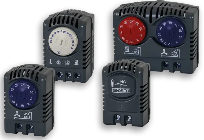
SCE Thermostats
Control Range | ||
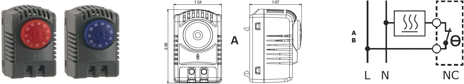
A | SCE-TEMNC | 14 – 176°F |
| SCE-TEMNO | 14 – 176°F | |
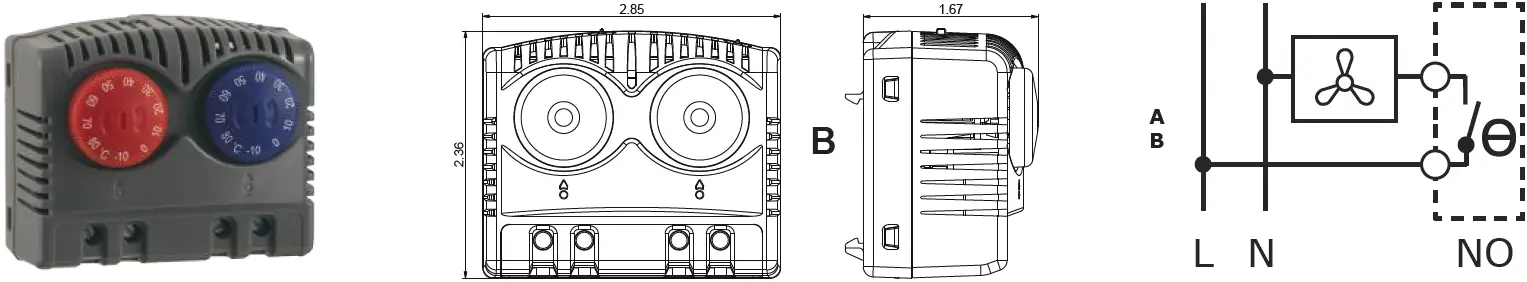
B | SCE-TEMD | 14 – 176°F |
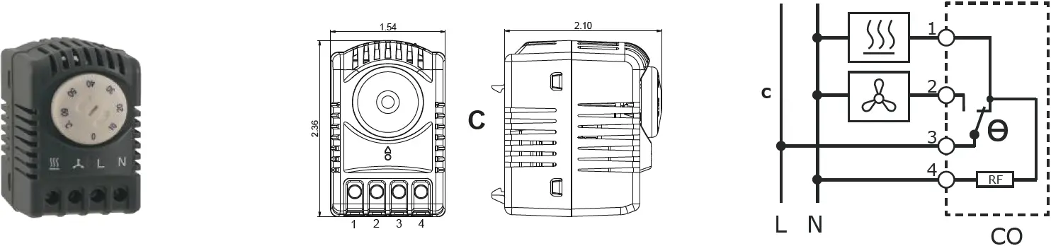
C | SCE-CTEM | 32 – 140°F |
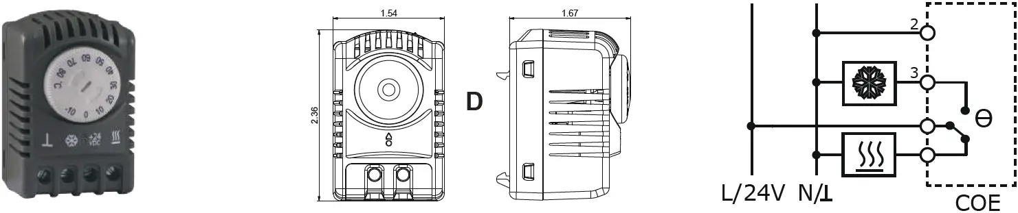
D | SCE-TEMEVDC | 14 – 176°F |
Safety Information
This component must be installed/serviced by qualified personnel complying with the relevant safety regulations in force and in accordance with the wiring diagram shown on the housing and represented in this manual. Ensure manuals are kept in a secure place accessible to servicing/installing personnel.
Device Description
This device has been designed specifically for cabinet temperature control.
Manually Adjustable Thermostat
Knob Color | With temperature rising, at the set temperature: |
Red NC | Breaks Contact |
Blue NO | Makes Contact |
White CO | Breaks Contact 3 to 1 |
White COE | Electronic Adjustable Thermostat |
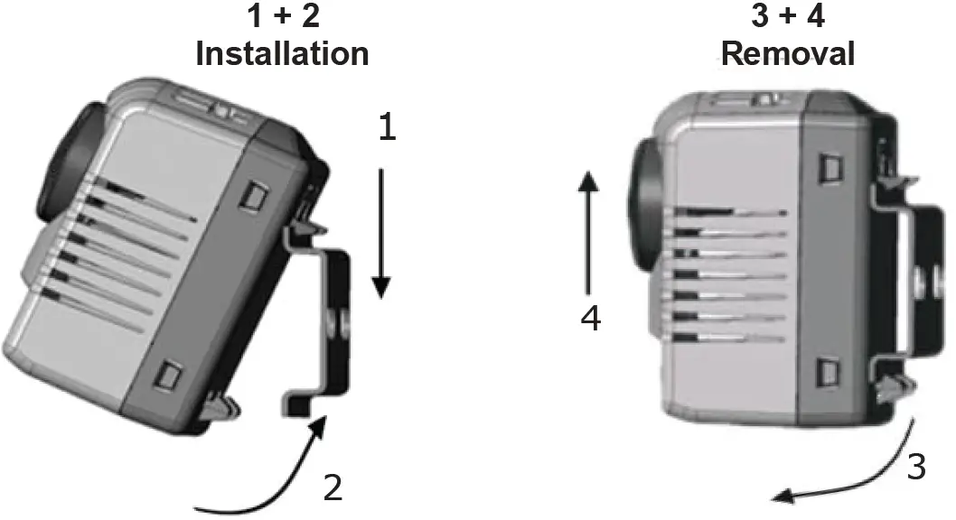
Installation
The device has been designed for installation on a DIN EN 60715 compliant standard rail. Preferably, it should be installed in the upper part of the cabinet with maximum separation from heat generating components. Thermostat’s ventilation slots must not be covered.
Switching Capacity | pf 0.95 | pf 0.75 | ||
AC | max. 250 V | A/B | 16 A | 2 A |
C | 10 A | 2 A | ||
DC | A/B/C | max. 72 V DC / max. 30 W | ||
D | 24 V DC, 16 A resistive load | |||
A / B | C | D | |
| Hysteresis | 7K ±3K | 7K | ±3K / 5% |
| Switching Tolerance | ±4K | ±3K | ±3K / 5% |
Operating/Storage Temperature
- A/B: -49°F – 248°F
- C: 32°F – 140°F
- D: -13°F – 158°F
Connection: 0.5 – 2.5mm2 / 14 – 20 AWG
Housing Material: Plastic UL94V-2
![]()


