![]() 16FE+2GE/1SFP Rackmount Switch With 16-Port PoE
16FE+2GE/1SFP Rackmount Switch With 16-Port PoE
TEF1118P-16-150W/TEF1118P-16-250W
24FE+2GE/1SFP Rackmount Switch With 24-Port PoE
TEF1126P-24-250W/TEF1126P-24-410W
Quick Installation Guide
Package contents
- Switch * 1
- Power cord * 1
- Footpad * 4
- L-shaped Brackett * 2
- Screw * 8
- Quick installation guide * 1
If any item is missing, damaged, or incorrect, please keep the original package and contact the local reseller or distributor immediately.
Installing the switch
* TEF1118P-16-150W is used for illustration. Select one mounting method as required.
Option A. Desktop mounting
Step 1 Place the switch upside down on a stable and flat desktop.
Step 2 Paste the four footpad stickers to the corresponding four recesses on the bottom of the switch.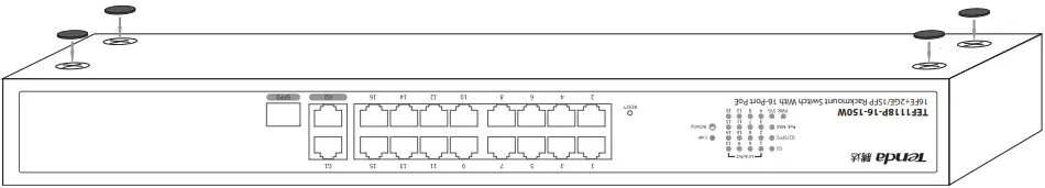 Step 3 Place the switch right side up on the desktop.
Option B. Rack mounting
Step 1 Ensure that the subrack is stable, level, and properly grounded.
Step 2 Fix L-shaped brackets to the switch with screws in the package. See the following figure.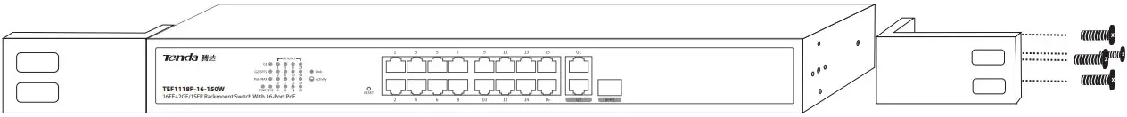 Step 3 Mount the switch at a proper height on the subrack and fix it to the rack with screws.
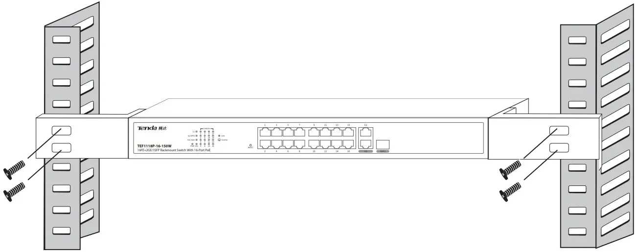 Option C. Wall mounting
Step 1 Fix L-shaped brackets to the switch with screws in the package.
Step 2 Attach the switch horizontally to the wall with the RJ45 ports upward, and mark the position of the screw holes on the wall with a marking pen. Drill 4 holes in the marking position with a churn drill, and then knock expansion bolts (self-prepared) into the holes.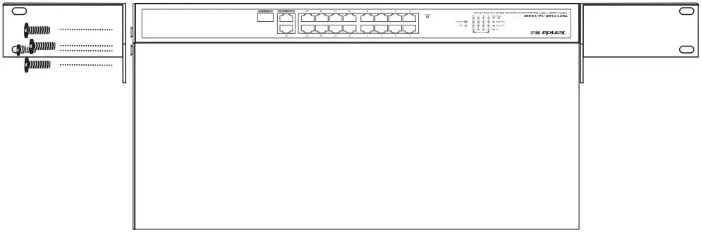 Step 3 Put the RJ45 ports upward, thread the screws through the holes on the L-type brackets, and fix them into the expansion bolts using a screwdriver to hang the switch onto the wall firmly.
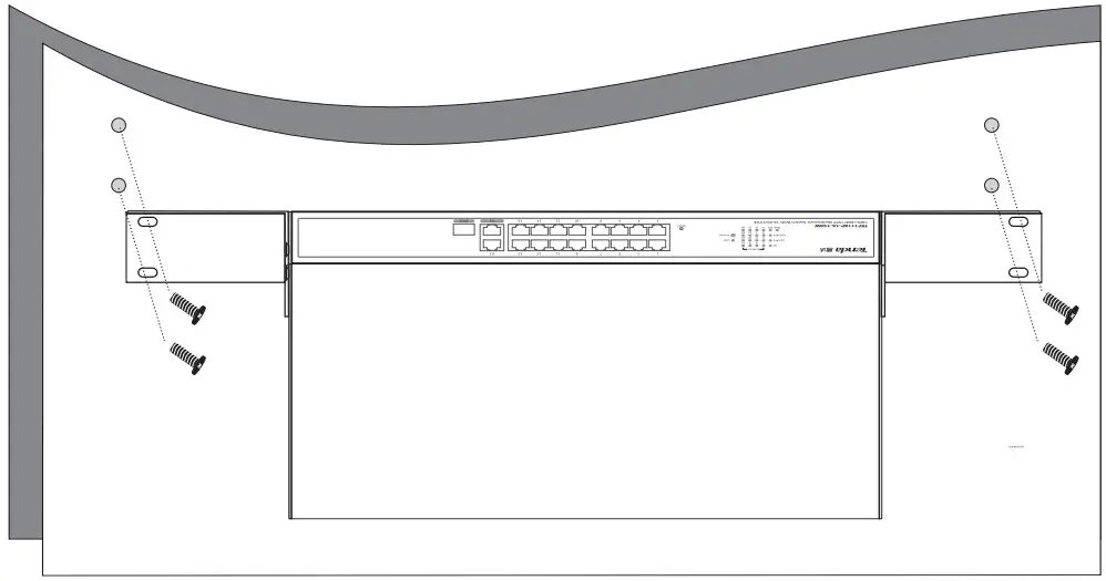
Connecting your devices
TEF1118P-16-150W is used for illustration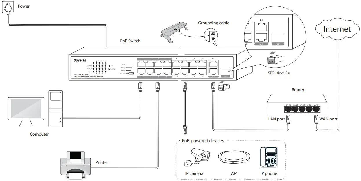
![]() Tips:
Tips:
- The switch supports the auto MDI/MDIX function, indicating that either straight cables or crossover cables are acceptable to connect your switch to Ethernet devices.
- To protect the switch from overload, the PoE ports of your switch are assigned with power supply priorities, and the priorities decrease as the port number increases. When the total power consumption of the PoE-powered devices exceeds the maximum output of the switch, the switch starts cutting the power supply from the port with the lowest priority, until the total consumption does not exceed the maximum output.
- Ports G2 and SFP2 compose a combo port, and port SFP2 owns the higher priority.
- For safety, do not face the air vents of the switch down when you use wall mounting.
LED indicators
| LED indicator | Status | Description |
| G1, G2/SFP2, Link/Act | Solid on | The corresponding port is connected properly. |
| Blinking | Data is being transmitted over the corresponding port. | |
| Off | The corresponding port is disconnected or improperly connected. | |
| PoE MAX | Solid on | The total output power of the switch reaches the maximum value. |
| Off | The total output power of the switch does not reach the maximum value. | |
| PWR | Solid on | The switch is connected to a power source properly. |
| Off | The switch is disconnected from a power source or not properly connected to a power source. |
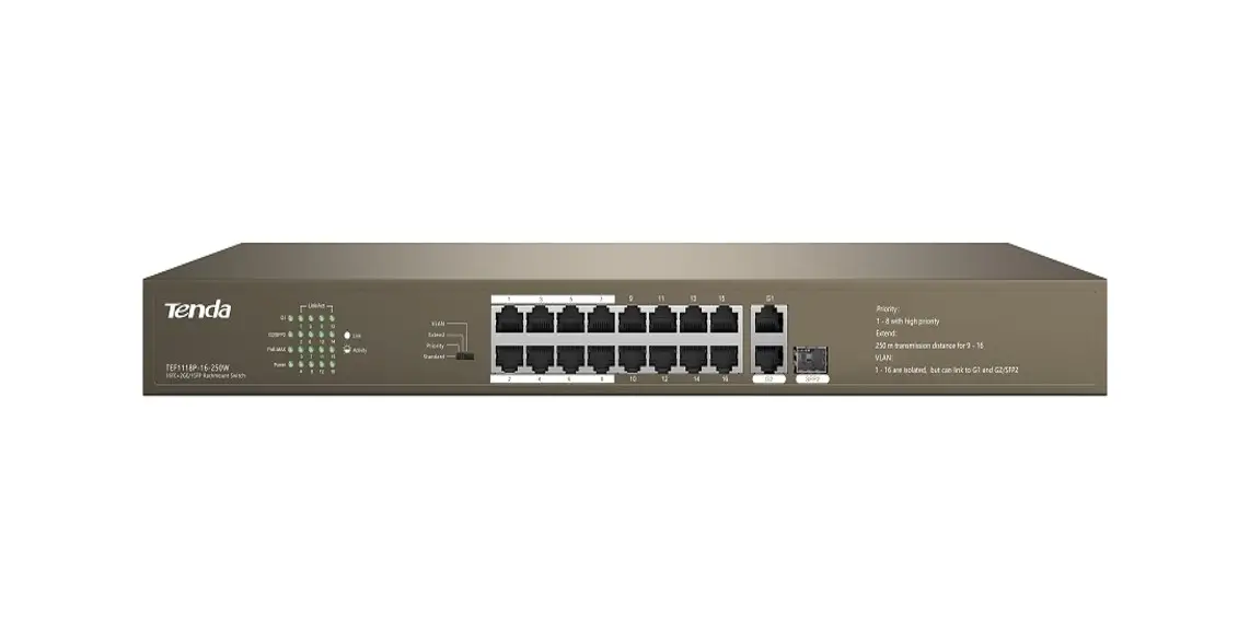
Working mode introduction
The PoE switch has 4 modes: Standard, Priority, Extend, and VLAN. You can use the working mode toggle to set the PoE switch to the required mode according to the following descriptions.
Standard: Default mode of the switch. In this mode, it works as an unmanaged switch; all ports can communicate with each other separately.
Priority: In this mode, ports G1 and G2/SFP2 serve as uplink ports, and ports 1 – 8 serve as high-priority ports. All ports can communicate with each other separately.
It is recommended to use this mode when there are multiple IP cameras connected to the switch.
In this mode, with the surveillance camera connected to the port with high priority and uplink devices (NVR, routers) connected to the two uplink ports, it ensures you a higher priority level for better internet connection when network congestion occurs.
Extend: In this mode, for switch TEF1118P-16-150W and TEF1118P-16-250W, the data rate of ports 9 –16 reduces to 10 Mbps, the maximum transmission distance can be 250 meters, and all ports can communicate with each other.
For switches TEF1126P-24-250W and TEF1126P-24-410W, the data rate of ports 17 – 24 reduces to 10 Mbps, the maximum transmission distance can be 250 meters, and all ports can communicate with each other.
VLAN: In this mode, for switch TEF1118P-16-150W and TEF1118P-16-250W, ports 1 – 16 can communicate with port G1, G2/SFP2 separately, but cannot communicate with each other. While for switch TEF1126P-24-250W and TEF1126P-24-410W, ports 1 – 24 can communicate with port G1, G2/SFP2 separately, but cannot communicate with each other. You can enable this mode to reduce broadcast storms and isolate DHCP broadcasts.
Specifications
Model | TEF1118P-16-150W | TEF1118P-16-250W | TEF1126P-24-250W | TEF1126P-24-410W | |
| Interface | 10/100/1000 Mbps RJ45 port | 2 | 2 | 2 | 2 |
| 10/100 Mbps RJ45 port | 16 | 16 | 24 | 24 | |
| 1000 Mbps SFP port | 1 Port SFP2 and port G2 compose a combo port, and the SFP port owns a higher priority. | ||||
| Working mode | Standard: Default mode of the switch. In this mode, it works as an unmanaged switch; all ports can communicate with each other separately. | ||||
| Priority: In this mode, ports G1 and G2/SFP2 serve as uplink ports, and ports 1 – 8 serve as high-priority ports. All ports can communicate with each other separately. | |||||
| Extend: In this mode, the data rate of ports 9 – 16 reduces to 10 Mbps, the maximum transmission distance can be 250 meters, and all ports can communicate with each other. | Extend: In this mode, the data rate of ports 17 – 24 reduces to 10 Mbps, the maximum transmission distance can be 250 meters, and all ports can communicate with each other. | ||||
| VLAN: In this mode, ports 1 – 16 of the switch can communicate with ports G1, G2/SFP2 separately, but cannot communicate with each other. You can enable this mode to reduce broadcast storms and isolate DHCP broadcasts. | VLAN: In this mode, ports 1 – 24 of the switch can communicate with ports G1, G2/SFP2 separately, but cannot communicate with each other. You can enable this mode to reduce broadcast storms and isolate DHCP broadcasts. | ||||
| Feature | Store-and-forward | Supported | |||
| MAC Address Table | 4 K | 16 K | |||
| MAC Address Learning | Self-learning, auto-aging | ||||
| Backplane Bandwidth | 7.2 Gbps | 7.2 Gbps | 8.8 Gbps | 8.8 Gbps | |
| PoE power supply | PoE standard | IEEE 802.3af, IEEE 802.3at | |||
| PoE port | 1 – 16 | 1 – 16 | 1 – 24 | 1 – 24 | |
| Maximum output of a single port | 30 W | 30 W | 30 W | 30 W | |
| Maximum output of the switch | 130 W | 230 W | 230 W | 370 W | |
| PoE power cable core | 8 cores: voltage of cores 1, 2, 4, and 5 is +, and cores 3, 6, 7, and 8 are -. | ||||
| Lightning protection | RJ45 port | Common mode: 6 kV | |||
| Power supply | Common mode: 6 kV Differential mode: 4 kV | ||||
| Environment | Operating environment | Temperature: (0 – 45)°C Humidity: (10% – 90%) RH, non-condensing | |||
| Storage environment | Temperature: (-40 – 70)°C Humidity: (5% – 90%) RH, non-condensing | ||||
| Input voltage | 100-240V AC 50/60Hz 2.0A | 100-240V AC 50/60Hz 4.0A | 100-240V AC 50/60Hz 4.0A | 100-240V AC 50/60Hz 6.0A | |
| Dimension | 294 * 178.8 * 44 mm | 440 * 178.8 * 44 mm | 440 * 178.8 * 44 mm | 440 * 284 * 44 mm | |
| Transmission data rate | Ethernet: 10 Mbps (half-duplex)/20 Mbps (full-duplex) Fast Ethernet: 100 Mbps (half-duplex)/200 Mbps (full-duplex) Gigabit Ethernet: 2000 Mbps (full-duplex) | ||||
| Transmission media | Ethernet: CAT3 UTP/STP cable or better Fast Ethernet: CAT5 UTP/STP cable or better Gigabit Ethernet: CAT5e or CAT6 UTP/STP cable (recommended) | ||||
| Standards | IEEE 802.3, IEEE 802.3u, IEEE 802.3x, IEEE 802.3ab, IEEE 802.3af, IEEE 802.3at, IEEE 802.3z | ||||
Safety Precautions
Before performing an operation, read the operation instructions and precautions to be taken, and follow them to prevent accidents. The warning and danger items in other documents do not cover all the safety precautions that must be followed. They are only supplementary information, the installation and maintenance personnel need to understand the basic safety precautions to be taken.
- Do not use this apparatus near water.
- Clean only with a dry cloth.
- Do not block any ventilation openings, such as newspapers, table-cloth, curtains, etc.
- Do not install near any heat sources such as radiators, heat registers, stoves, or other apparatus that produce heat.
- Do not damage the ground conductor or operate the device in the absence of a well-installed ground conductor. Conduct the appropriate electrical inspection.
- Protect the power cord from being walked on or pinched particularly at the plugs, convenience receptacles, and at the point where they exit from the apparatus.
- Only use attachments/accessories specified by the manufacturer.
- Unplug this apparatus during lightning storms or when unused for long periods of time.
- The mains plug is used as the disconnect device, the disconnect device shall remain readily operable.
- Refer all servicing to qualified service personnel. Servicing is required when the apparatus has been damaged in any way, such as power-supply cord or plug is damaged, liquid has been spilled or objects have fallen into the apparatus, the apparatus has been exposed to rain or moisture, does not operate normally, or has been dropped.
- Warning: To reduce the risk of fire or electric shock, do not expose this apparatus to rain or moisture. The apparatus shall not be exposed to dripping or splashing.
- Warning: To reduce the risk of electric shock, do not remove the cover as there are no user-serviceable parts inside. Refer servicing to qualified personnel.
![]()
CE Mark Warning
This is a Class A product. In a domestic environment, this product may cause radio interference, in which case the user may be required to take adequate measures.
The mains plug is used as a disconnect device; the disconnect device shall remain readily operable.
NOTE: (1) The manufacturer is not responsible for any radio or TV interference caused by unauthorized modifications to this equipment. (2) To avoid unnecessary radiation interference, it is recommended to use a shielded RJ45 cable.![]()
![]() Caution:
Caution:
TEF1118P-16-150W
Input: 100 – 240 V AC 50/60 Hz, 2.0 A
Output: 53.5 V ![]() 2.8 A
2.8 A![]() : DC Voltage
: DC Voltage
TEF1118P-16-250W/TEF1126P-24-250W
Input: 100-240V AC 50/60Hz 4.0A
Output: 53.5 V ![]() 4.7A
4.7A
TEF1126P-24-410W
Input: 100 – 240 V AC 50/60 Hz, 6A
Output: 53.5 V ![]() 7.7A
7.7A
![]()
FCC Statement
This equipment has been tested and found to comply with the limits for a Class A digital device, pursuant to Part 15 of the FCC Rules. These limits are designed to provide reasonable protection against harmful interference when the equipment is operated in a commercial environment. This equipment generates, uses, and can radiate radio frequency energy and, if not installed and used in accordance with the instruction manual, may cause harmful interference to radio communications. Operation of this equipment in a residential area is likely to cause harmful interference in which case the user will be required to correct the interference at his own expense.
Operation is subject to the following two conditions: (1) this device may not cause harmful interference, and (2) this device must accept any interference received, including interference that may cause undesired operation.
Caution!
Any changes or modifications not expressly approved by the party responsible for compliance could void the user’s authority to operate the equipment.
NOTE: (1) The manufacturer is not responsible for any radio or TV interference caused by unauthorized modifications to this equipment. (2) To avoid unnecessary radiation interference, it is recommended to use a shielded RJ45 cable.![]() RECYCLING
RECYCLING
This product bears the selective sorting symbol for Waste electrical and electronic equipment (WEEE). This means that this product must be handled pursuant to European directive 2012/19/EU in order to be recycled or dismantled to minimize its impact on the environment.
User has the choice to give their product to a competent recycling organization or to the retailer when he buys new electrical or electronic equipment.
Technical Support
Shenzhen Tenda Technology Co., Ltd.
6-8 Floor, Tower E3, NO.1001, Zhongshanyuan Road,
Nanshan District, Shenzhen, China. 518052
USA hotline: 1-800-570-5892
Toll-Free: Daily-9 am to 6 pm PST
Canada hotline: 1-888-998-8966
Toll Free: Mon – Fri 9 am – 6 pm PST
HongKong Hotline: 00852-81931998
Global Hotline: +86 755-2765 7180 (China Time Zone)
Website: www.tendacn.com
E-mail: [email protected]
Copyright
Copyright © 2019 Shenzhen Tenda Technology Co., Ltd. All rights reserved.
Tenda is a registered trademark legally held by Shenzhen Tenda Technology Co., Ltd.
Other brand and product names mentioned herein are trademarks or registered
trademarks of their respective holders. Specifications are subject to change without notice.


 Plus 2g Combo Poe Switch Installation Guide")


