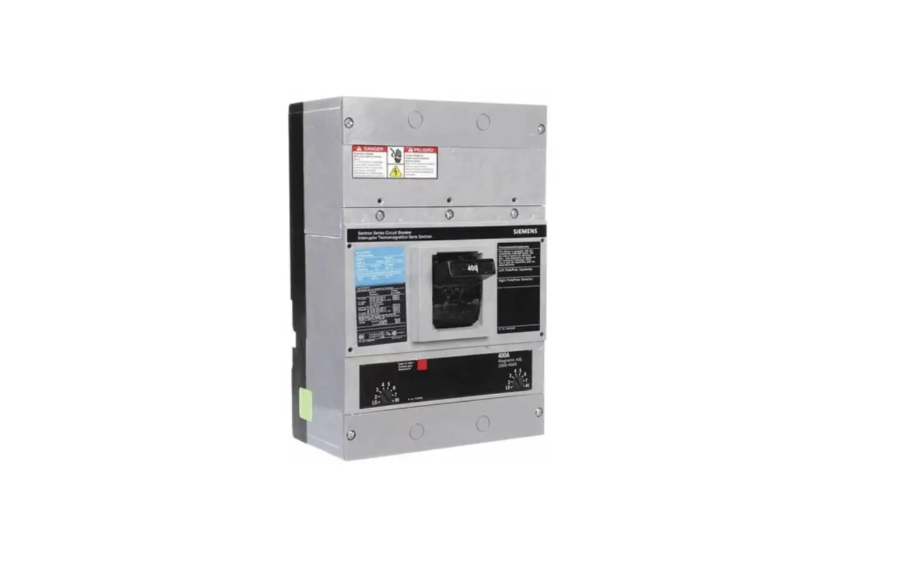
SIEMENS JXD2(-A) Molded Case Circuit Breaker Instruction Manual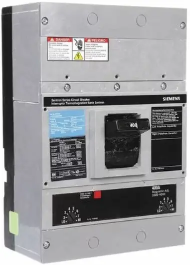
Installation Instructions
![]() Danger
Danger
 Hazardous voltage. Will cause death or serious injury.
Turn OFF and lock out all power supplying this device before installing or servicing accessory
SAFETY INSTRUCTIONS
| BREAKERS TYPES | |
| JXD2(-A), JXD6(-A), JXD6(-A)ETI, HJXD6(-A), HHJXD6, SJD6(-A), SHJD6(-A), JFC, JFF, JM6, JMK | CJD6(-A), CJD6(-A)ETI, SCJD6(-A), JDFP(-A) |
| LXD6(-A), LXD6(-A)ETI, HLXD6(-A), HHLXD6(-A), SLD6(-A), SHLD6(-A), LFC, LFF, LM6, LMK | CLD6(-A), CLD6(-A)ETI, SCLD6(-A), LDFP(-A) |
NOTE: These instructions outline the recommended installation procedure.
- Circuit Breaker Preparation
The circuit breaker should be in the OFF/”O” position before installing the plug-in-tulip adapter kit. Turn off and lock out all power supplying this device before installing. Verify that NO voltage is present before proceeding with task.
BREAKER PREPARATION: REMOVE PRESSURE WIRE CONNECTORS FROM BREAKER IF PRESENT - Place tulip clip assembly (5) on back of breaker in recess provided in base molding. Secure in place with ¼” belleville washers (6) and ¼”-20 X 1 hex head bolts (7) furnished. Recommended tightening torque for these bolts is 60 72 in-lbs. [6.78-8.13 N/m] to assure a good electrical connection. Repeat this procedure for the remaining tulip clip assemblies.
- Note: For Current Limiting Circuit Breakers Load end only. (See pg. 3). Place tulip clip assembly (5) on back of breaker terminal. Attach and shield bracket (13) (From end shield assembly, catalog number’s CLTCJL2 or CLTCJL3) from front of breaker as shown in fig. 4a. Secure in place with ¼ in. belleville washers (6) and ¼-20 x 1 in. hex head bolts (7) furnished. Tighten bolts to 60-72 in-lbs. [6.78-8.13 N/m] to assure a good electrical connection.
- Attach end shield (14) to end shield bracket (13) using the four molded pan head screws (15). Tighten screws to 5 in-lbs. [.56 N/m] max.
- Slide one piece end shields (8) into slots provided in breaker case at line and load ends of breaker.
Note: For Current Limiting Circuit Breakers, attach one piece end shields to load end only. - Attach terminal shields to line and load side of circuit breaker.
- Add accessory label (9) to top of breaker as indicated in figures.
![]() Danger Hazardous voltage. Will cause death or serious injury.
Danger Hazardous voltage. Will cause death or serious injury.
Turn OFF and lock out all power supplying this device before installing or servicing accessory.
Installation Instructions
JXD2(-A), JXD6(-A), JXD6(-A)ETI, HJXD6(-A), HHJXD6, SJD6(-A), JFC, JFF, LXD6(-A), LXD6(-A)ETI, HLXD6(-A), HHLXD6(-A), SLD6(-A), SHLD(-A), LFC, LFF, JM6, JMK, LM6, LMK
TCJ2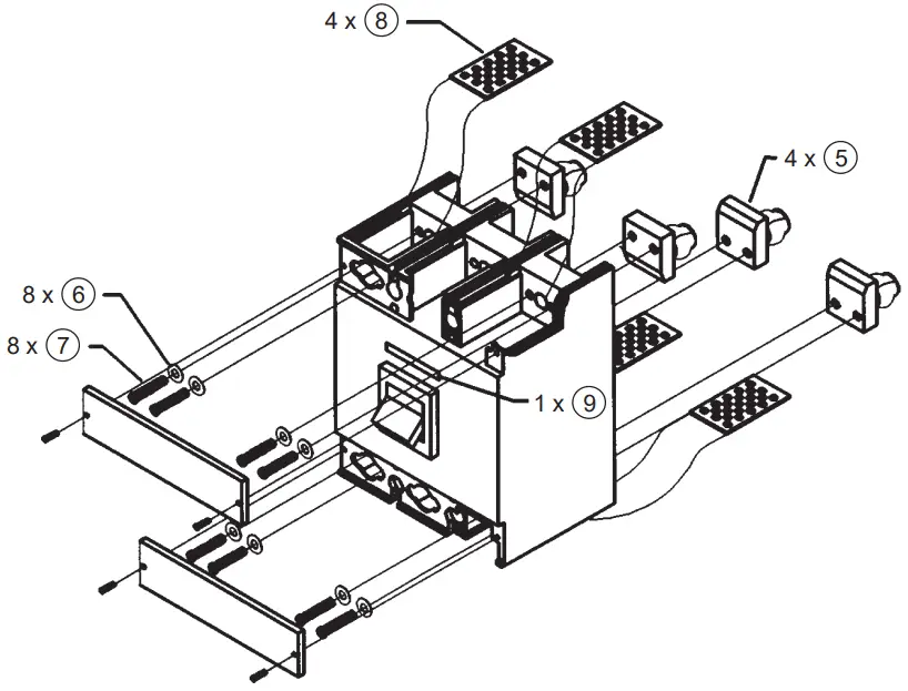
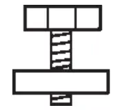 | |
¼ – 20 x 1 | [6.78-8.13 Nm] 60-72 LB.IN. |
TCJ3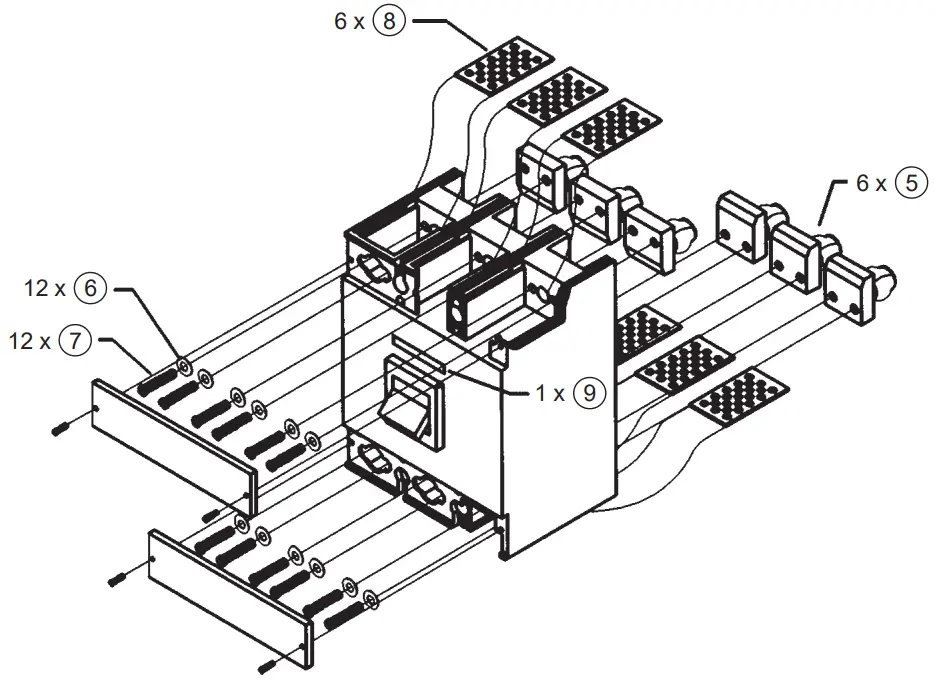
![]() Danger
Danger
Hazardous voltage. Will cause death or serious injury. Turn OFF and lock out all power supplying this device before installing or servicing accessory.
| CJD6(-A), CJD6(-A)ETI, SCJD6(-A) |
| CLD6(-A), CLD6(-A)ETI, SCLD6(-A) |
TCJ2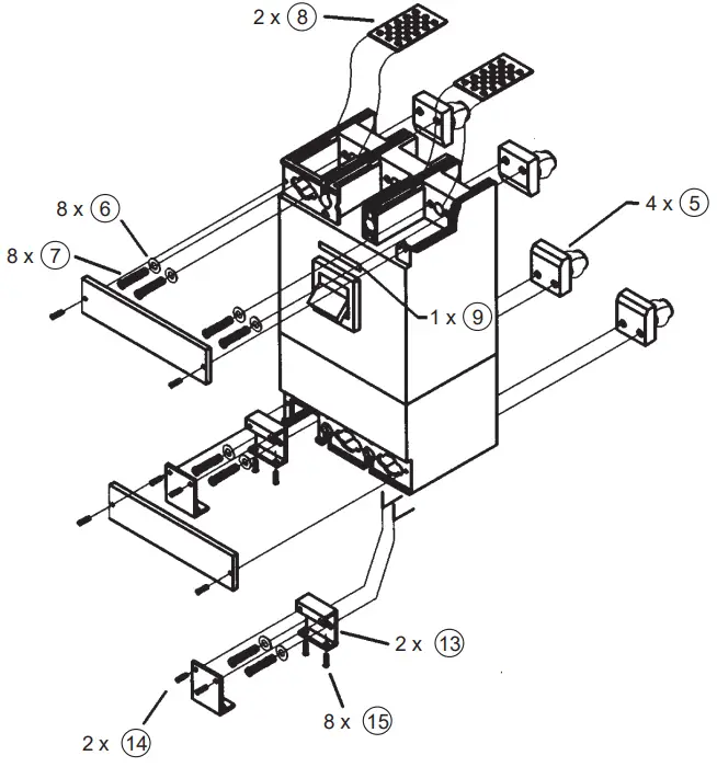
TCJ3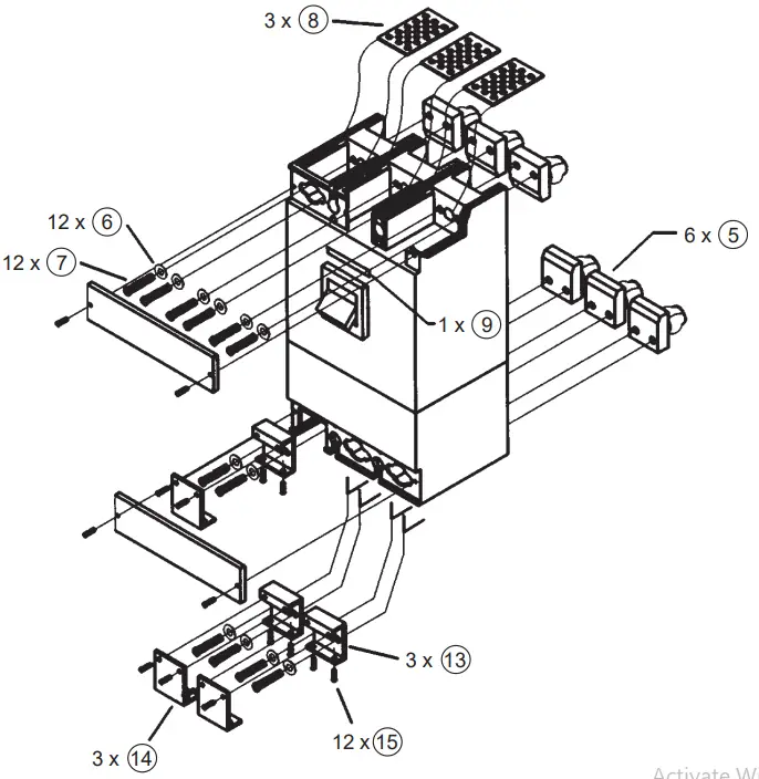
| |
7 ¼ – 20 x 1 | 6.78-8.13 Nm] 60-72 Lb.In. |
| 15 | [.56 Nm] 5 Lb.In. |
![]()


