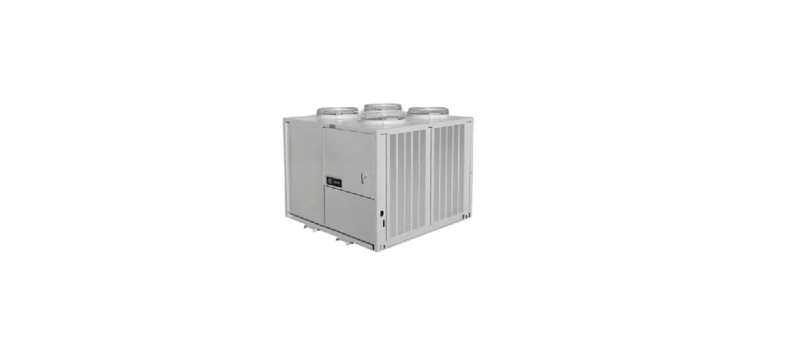
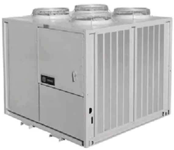
TRANE BAYDDCU600 Air-Cooled Condensing DDC Controller Options Remote Split System
SAFETY WARNING
Only qualified personnel should install and service the equipment. The installation, starting up, and servicing of heating, ventilating, and air-conditioning equipment can be hazardous and requires specific knowledge and training. Improperly installed, adjusted or altered equipment by an unqualified person could result in death or serious injury. When working on the equipment, observe all precautions in the literature and on the tags, stickers, and labels that are attached to the equipment.
Introduction
Warnings, Cautions, and Notices
Safety advisories appear throughout this manual as required. Your personal safety and the proper operation of this machine depend upon the strict observance of these precautions.
The three types of advisories are defined as follows:
- WARNING: Indicates a potentially hazardous situation which, if not avoided, could result in death or serious injury.
- CAUTION: Indicates a potentially hazardous situation which, if not avoided, could result in minor or moderate injury. It could also be used to alert against unsafe practices.
- NOTICE: Indicates a situation that could result in equipment or property-damage only accidents.
Important Environmental Concerns
Scientific research has shown that certain man-made chemicals can affect the earth’s naturally occurring stratospheric ozone layer when released to the atmosphere. In particular, several of the identified chemicals that may affect the ozone layer are refrigerants that contain Chlorine, Fluorine and Carbon (CFCs) and those containing Hydrogen, Chlorine, Fluorine and Carbon (HCFCs). Not all refrigerants containing these compounds have the same potential impact to the environment. Trane advocates the responsible handling of all refrigerants-including industry replacements for CFCs and HCFCs such as saturated or unsaturated HFCs and HCFCs.
Important Responsible Refrigerant Practices
Trane believes that responsible refrigerant practices are important to the environment, our customers, and the air conditioning industry. All technicians who handle refrigerants must be certified according to local rules. For the USA, the Federal Clean Air Act (Section 608) sets forth the requirements for handling, reclaiming, recovering and recycling of certain refrigerants and the equipment that is used in these service procedures. In addition, some states or municipalities may have additional requirements that must also be adhered to for responsible management of refrigerants. Know the applicable laws and follow them.
WARNING: Proper Field Wiring and Grounding Required!
Failure to follow code could result in death or serious injury. All field wiring MUST be performed by qualified personnel. Improperly installed and grounded field wiring poses FIRE and ELECTROCUTION hazards. To avoid these hazards, you MUST follow requirements for field wiring installation and grounding as described in NEC and your local/state/national electrical codes.
WARNING: Personal Protective Equipment (PPE) Required!
Failure to wear proper PPE for the job being undertaken could result in death or serious injury. Technicians, in order to protect themselves from potential electrical, mechanical, and chemical hazards, MUST follow precautions in this manual and on the tags, stickers, and labels, as well as the instructions below:
- Before installing/servicing this unit, technicians MUST put on all PPE required for the work being undertaken (Examples; cut resistant gloves/sleeves, butyl gloves, safety glasses, hard hat/bump cap, fall protection, electrical PPE and arc flash clothing). ALWAYS refer to appropriate Safety Data Sheets (SDS) and OSHA guidelines for proper PPE.
- When working with or around hazardous chemicals, ALWAYS refer to the appropriate SDS and OSHA/GHS (Global Harmonized System of Classification and Labeling of Chemicals) guidelines for information on allowable personal exposure levels, proper respiratory protection and handling instructions.
- If there is a risk of energized electrical contact, arc, or flash, technicians MUST put on all PPE in accordance with OSHA, NFPA 70E, or other country-specific requirements for arc flash protection, PRIOR to servicing the unit. NEVER PERFORM ANY SWITCHING, DISCONNECTING, OR VOLTAGE TESTING WITHOUT PROPER ELECTRICAL PPE AND ARC FLASH CLOTHING. ENSURE ELECTRICAL METERS AND EQUIPMENT ARE PROPERLY RATED FOR INTENDED VOLTAGE.
WARNING: Follow EHS Policies!
Failure to follow instructions below could result in death or serious injury.
- All Trane personnel must follow the company’s Environmental, Health and Safety (EHS) policies when performing work such as hot work, electrical, fall protection, lockout/tagout, refrigerant handling, etc. Where local regulations are more stringent than these policies, those regulations supersede these policies.
- Non-Trane personnel should always follow local regulations.
Copyright
This document and the information in it are the property of Trane, and may not be used or reproduced in whole or in part without written permission. Trane reserves the right to revise this publication at any time, and to make changes to its content without obligation to notify any person of such revision or change.
Trademarks
All trademarks referenced in this document are the trademarks of their respective owners.
Overview
Receipt of Kit
Inspect the unit for damage. Check internal components for damage. If inspection reveals damage or material shortages, file a claim with the shipper immediately. Specify the type and extent of the shipping damage on the Bill of Lading before signing. It is the responsibility of the purchasing contractor to file the freight claim; failure to do so makes the purchaser financially responsible for shipping damage. Do not install a damaged unit without approval from the appropriate Trane sales representative.
Field Supplied and Installed Items (AHU)
- Zone Sensor with Setpoint (CV or VAV control units only)
- Discharge Air Temperature Sensor (VAV control units only)
- Conventional Thermostat (field supplied, thermostat controlled units Only)
- Outdoor Air Temperature Sensor (factory-wired, field-installed)
- Occupancy Contacts (CV or VAV control units)
- Evaporator Fan Interlock
Field Supplied and Installed Items (Chiller)
- Chiller Enable Contacts
- Chiller Leaving Water Temperature Sensor
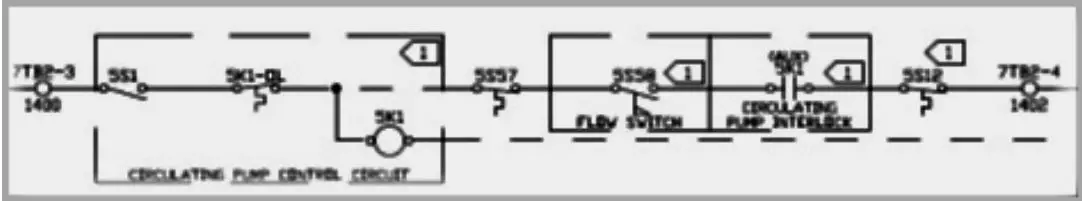
- Circulating Pump Control Circuit
- Flow Switch
- Circulating Pump Interlock
- Freezestat
Unit Control (AHU)
- This unit will control based on field application and set by jumper position. Default is Thermostat Control.
- This unit is designed to operate at ambient temperatures above 40°F. When the outside air (OA) temperature is below 40°F as read by the outdoor air temperature sensor on UI11, all compressors will be commanded off.
- All default values and setpoints are adjustable using the Tracer TU service tool.
Unit Control (Chiller)
- If the outdoor air temperature is within the ambient temperature window (40° and 125°F adjustable), the chiller will be allowed to operate.
- Upon a chiller-enable signal, the unit controller will stage compressors to maintain the leaving water temperature at setpoint (45°F adjustable).
- Chiller may be remotely disabled regardless of local enable by setting Chiller Disable BAS (Binary Value 1) to Disabled.
- If leaving-water temperature is at or below 36°F (adjustable if the correct percent solution of glycol is in the system), the UC controller will go into freeze protection lockout.
Occupancy Switch Notes (AHU)
- An occupancy switch must be field wired to 7TB2-12 and 7TB2-13 for proper operation.
- When the occupancy switch is closed the unit will be occupied. When the occupancy switch is open the unit will be unoccupied.
- Occupancy may be communicated to the unit via Multi-state Value 2, but the unit control must be set to BAS. See points list for additional details.
Outdoor Air Temperature Sensor Notes (AHU and Chiller)
- The outdoor air (OA) sensor is factory wired to the UC controller and is supplied with enough wire to reach the mounting point.
- Use the bracket that is included in the unit to mount the OA sensor to the air entering side of the condenser coils.
Occupied Sequence of Operation (AHU)
- Thermostat Control Units:
- Fan operation must be proven via contact closure across terminals 7TB2-3 and 7TB2-4. Once fan is proven and the unit is in occupied mode, a field-supplied thermostat or sequencer will call on compressors with contact closures across universal inputs UI1 to UI6. Normally, open contacts for compressor staging will be wired to terminals 7TB2-5 to 7TB2-11 for cool calls 1 to 6, respectively.
- Constant Air Volume (CV) Control Units:
- Fan operation must be proven via contact closure across terminals 7TB2-3 and 7TB2-4. A fieldinstalled space temperature sensor with setpoint (BAYSENS075A) must be wired to 7TB2-16 to 7TB2- 18 according to the wiring diagram. Once fan is proven and the unit is in occupied mode, the compressors will be controlled by the Tracer UC600 to maintain space temperature at setpoint.
- Variable Air Volume (VAV) Control Units:
- Fan operation must be proven via contact closure across terminals 7TB2-3 and 7TB2-4. A fieldinstalled discharge air temperature sensor (10K, Type II thermistor) must be wired to 7TB2-14 and 7TB2-15 according to the wiring diagram. Once fan is proven and the unit is in occupied mode, the compressors will be controlled by the Tracer UC600 to maintain discharge air temperature at setpoint. Default value is 55°F.
Supply Fan Control Notes (AHU)
- The supply fan is controlled by others. Fan status must be hardwired to the Tracer UC600 across terminals 7TB2-3 and 7TB2-4 for proper operation.
General Control Notes (AHU)
- Unit controls shall maintain minimum on and off timers to protect compressors from short cycling.
- Factory safeties (for example, High/Low pressure, temperature) are re-wired to allow for monitoring and diagnostic capability with the Tracer UC600. The only factory components that are replaced by the DDC controller are compressor on/off timers.
- In unoccupied cooling mode, this unit will stage compressors to maintain temperature at unoccupied cooling setpoint.
- The Tracer UC600 will monitor safety status and lock out compressors if a safety trips three consecutive times in one hour. This hard lockout must be reset by cycling power to the unit. A soft lockout will occur if a high-pressure or low-pressure safety trips and will shut the circuit’s compressors off for at least three minutes. The safety resets itself.
- Tracer UC600 will maintain a 3-minute inter-stage timer when ramping stages of cooling up and down.
- Cool Calc P-Gain may need to be adjusted on startup to optimize cooling operation.
General Control Notes (Chiller)
- Unit controls shall maintain minimum on and off timers to protect compressors from short cycling.
- Factory safeties (for example, High/Low pressure, temperature) are rewired to allow for monitoring and diagnostic capability with the Tracer UC600. The only factory components replaced by the DDC controller are compressor on/off timers.
- Pump Interlock, Flow Switch, and Freezestat must be field-wired in series with Chiller Enable to allow chiller operation. Circulating Pump Control is optional.
- The Tracer UC600 will monitor safety status and lock out compressors if a safety trips three consecutive times in one hour. This hard lockout must be reset by cycling power to the unit. A soft lockout will occur is a high-pressure or low-pressure safety trips and will shut the circuit’s compressors off for at least three minutes. The safety resets itself.
- Tracer UC600 will maintain a three-minute inter-stage timer when ramping stages of cooling up and down.
- Cool Calc P-Gain may need to be adjusted on startup to optimize chiller operation.
Backplate Installation
WARNING: Hazardous Service Procedures!
Failure to follow all precautions in this manual and on the tags, stickers, and labels could result in death or serious injury.
Technicians, in order to protect themselves from potential electrical, mechanical, and chemical hazards, MUST follow precautions in this manual and on the tags, stickers, and labels, as well as the following instructions: Unless specified otherwise, disconnect all electrical power including remote disconnect and discharge all energy storing devices such as capacitors before servicing. Follow proper lockout/tagout procedures to ensure the power can not be inadvertently energized. When necessary to work with live electrical components, have a qualified licensed electrician or other individual who has been trained in handling live electrical components perform these tasks.
Important: Turn off main unit disconnect and lockout / tag out power supply.
- For 20 to 60 ton units, unplug connector 7P1 and 7P2.
- For 80 to 120 ton units unplug connectors 7P1, 7P2, and 7P3.
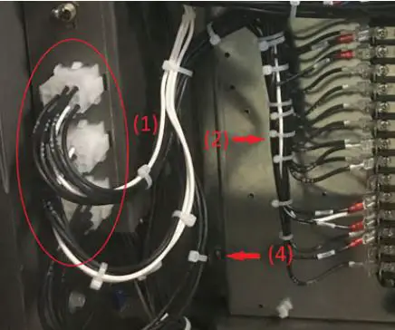
- Cut wire ties to free wires connected to components on the control panel.
- Remove the screws that fasten the back plate to the main control panel. Discard back plate.
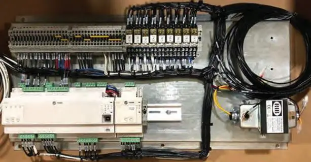
- Install the new back plate to the main electrical panel with provided sheet metal screws. On 80 to 120 ton units, install timers 7U5 and 7U6 in top left corner of back plate. Connect wires 58C to 7U5-1, 100B to 7U5-2, 36AW to 7U5-3, 71C to 7U6-1, 101B to 7U6-2, and 36AV to 7U6-3. Reference CST Supplied wiring diagram (lines 81 to 88).
- Note: Plug in new connector(s) 7P1, 7P2 (and 7P3 where applicable) into existing receptacle.
Diagnostics Rewiring Instructions 20 to 30T (AHU)
Reference CST Supplied Wiring Diagram for details regarding this section.
- Circuit 1 High Pressure Cutout:
- Remove wires 58A and 59A from 1TB3-7 and 1TB2-4, then splice with wires 1552G and 1559A respectively. Reference line 80 on BAYDDCU601A.60.00.
- Connect wire 1559B to 1TB2-4. Reference line 92 on BAYDDCU601A.60.00.
- Circuit 1 Low Pressure Cutout:
- Remove wire 57E from 1TB3-1 and splice with 1557A. Reference line 92 on BAYDDCU601A.60.00.
- Connect wire 1552H to 1TB3-1. Reference line 83 on BAYDDCU601A.60.00.
- Remove wire 61P from 1TB3-2 and rewire to 1TB3-7. Reference line 83 on BAYDDCU601A.60.00.
- Remove wire 98A from 1TB2-2 and splice with wire 1598A. Reference line 83 on BAYDDCU601A.60.00.
- Run wire 1561P from 1TB3-2 to 1TB2-2. Reference line 94 on BAYDDCU601A.60.00.
- Reset Relay Disconnect:
- Disconnect wires 53B and 53C from 1TB2-8 and splice together to isolate. Reference lines 92 to 94 on BAYDDCU601A.60.00
- Disconnect wires 66B and 66C from 1TB4-1 and splice together to isolate. Reference lines 109 to 112 on BAYDDCU601A.60.00
20 to 30T (Chiller)
Reference CST Supplied Wiring Diagram for details regarding this section.
- Circuit 1 High Pressure Cutout:
- Remove wires 58A and 59A from 1TB3-7 and 1TB2-4, then splice with wires 1552G and 1559A respectively. Reference line 80 on BAYDDCU602A.60.00.
- Connect wire 1559B to 1TB2-4. Reference line 92 on BAYDDCU602A.60.00.
- Circuit 1 Low Pressure Cutout:
- Remove wire 57E from 1TB3-1 and splice with 1557A. Reference line 92 on BAYDDCU602A.60.00.
- Connect wire 1552H to 1TB3-1. Reference line 83 on BAYDDCU602A.60.00.
- Remove wire 61P from 1TB3-2 and rewire to 1TB3-7. Reference line 83 on BAYDDCU602A.60.00.
- Remove wire 98A from 1TB2-2 and splice with wire 1598A. Reference line 83 on BAYDDCU602A.60.00.
- Run wire 1561P from 1TB3-2 to 1TB2-2. Reference line 94 on BAYDDCU602A.60.00.
- Reset Relay Disconnect:
- Disconnect wires 53B and 53C from 1TB2-8 and splice together to isolate. Reference lines 92 to 94 on BAYDDCU602A.60.00
- Disconnect wires 66B and 66C from 1TB4-1 and splice together to isolate. Reference lines 109 to 112 on BAYDDCU602A.60.00
40 to 60T (AHU)
Reference CST Supplied Wiring Diagram for details regarding this section.
- Circuit 1 High Pressure Cutout:
- Remove wires 58A and 59A from 1TB3-7 and 1TB2-4, then splice with wires 1552G and 1559A respectively. Reference line 80 on BAYDDCU603A.60.00.
- Connect wire 1559B to 1TB2-4. Reference line 92 on BAYDDCU603A.60.00.
- Circuit 1 Low Pressure Cutout:
- Remove wire 57E from 1TB3-1 and splice with 1557A. Reference line 92 on BAYDDCU603A.60.00.
- Connect wire 1552H to 1TB3-1. Reference line 83 on BAYDDCU603A.60.00.
- Remove wire 61P from 1TB3-2 and rewire to 1TB3-7. Reference line 83 on BAYDDCU603A.60.00.
- Remove wire 98A from 1TB2-2 and splice with wire 1598A. Reference line 83 on BAYDDCU603A.60.00.
- Run wire 1561P from 1TB3-2 to 1TB2-2. Reference line 94 on BAYDDCU603A.60.00.
- Circuit 2 High Pressure Cutout:
- Remove wires 71A and 72A from 1TB4-3 and 1TB4-6, then splice with wires 1552J and 1572A respectively. Reference line 85 on BAYDDCU603A.60.00.
- Connect wire 1572B to 1TB4-6. Reference line 112 on BAYDDCU603A.60.00
- Circuit 2 Low Pressure Cutout:
- Remove wire 70E from 1TB4-2 and splice with 1570A. Reference line 112 on BAYDDCU603A.60.00.
- Connect wire 1552K to 1TB4-2. Reference line 86 on BAYDDCU603A.60.00.
- Remove wires 74R 1TB4-5 and rewire to 1TB4-3. Reference line 86 on BAYDDCU603A.60.00.
- Remove wire 99A from 1TB4-8 and splice with wire 1599A. Reference line 86 on BAYDDCU603A.60.00.
- Run wire 1574R from 1TB4-5 to 1TB4-8. Reference line 109 on BAYDDCU603A.60.00.
- Reset Relay Disconnect:
- Disconnect wires 53B and 53C from 1TB2-8 and splice together to isolate. Reference lines 92 to 94 on BAYDDCU603A.60.00
- Disconnect wires 66B and 66C from 1TB4-1 and splice together to isolate. Reference lines 109 to 112 on BAYDDCU603A.60.00
40 to 60T (Chiller)
Reference CST Supplied Wiring Diagram for details regarding this section.
- Circuit 1 High Pressure Cutout:
- Remove wires 58A and 59A from 1TB3-7 and 1TB2-4, and splice with wires 1552G and 1559A, respectively. Reference line 80 on BAYDDCU604A.60.00.
- Connect wire 1559B to 1TB2-4. Reference line 92 on BAYDDCU604A.60.00.
- Circuit 1 Low Pressure Cutout:
- Remove wire 57E from 1TB3-1 and splice with 1557A. Reference line 92 on BAYDDCU604A.60.00.
- Connect wire 1552H to 1TB3-1. Reference line 83 on BAYDDCU604A.60.00.
- Remove wire 61P from 1TB3-2 and re-wire to 1TB3-7. Reference line 83 on BAYDDCU604A.60.00.
- Remove wire 98A from 1TB2-2 and splice with wire 1598A. Reference line 83 on BAYDDCU604A.60.00.
- Run wire 1561P from 1TB3-2 to 1TB2-2. Reference line 94 on BAYDDCU604A.60.00.
- Circuit 2 High Pressure Cutout:
- Remove wires 71A and 72A from 1TB4-3 and 1TB4-6, and splice with wires 1552J and 1572A, respectively. Reference line 85 on BAYDDCU604A.60.00.
- Connect wire 1572B to 1TB4-6. Reference line 112 on BAYDDCU604A.60.00
- Circuit 2 Low Pressure Cutout:
- Remove wire 70E from 1TB4-2 and splice with 1570A. Reference line 112 on BAYDDCU604A.60.00.
- Connect wire 1552K to 1TB4-2. Reference line 86 on BAYDDCU604A.60.00.
- Remove wires 74R 1TB4-5 and re-wire to 1TB4-3. Reference line 86 on BAYDDCU604A.60.00.
- Remove wire 99A from 1TB4-8 and splice with wire 1599A. Reference line 86 on BAYDDCU604A.60.00.
- Run wire 1574R from 1TB4-5 to 1TB4-8. Reference line 109 on BAYDDCU604A.60.00.
- Reset Relay Disconnect:
- Disconnect wires 53B and 53C from 1TB2-8 and splice together to isolate. Reference lines 92 to 94 on BAYDDCU604A.60.00
- Disconnect wires 66B and 66C from 1TB4-1 and splice together to isolate. Reference lines 109 to 112 on BAYDDCU604A.60.00
80 to 120T (AHU)
Reference CST Supplied Wiring Diagram for details regarding this section.
- Circuit 1 High Pressure Cutout:
- Remove wires 58A and 59A from 1TB3-7 and 1TB2-4, and splice with wires 1552J and 1559A, respectively. Reference line 80 on BAYDDCU605A.60.00.
- Connect wire 1559B to 1TB2-4. Reference line 93 on BAYDDCU605A.60.00.
- Circuit 1 Low Pressure Cutout:
- Remove wire 100F from 1TB3-1 and splice with 15100A. Reference line 93 on BAYDDCU605A.60.00.
- Connect wire 1552K to 1TB3-1. Reference line 93 on BAYDDCU605A.60.00.
- Remove wire 61P from 1TB3-2 and re-wire to 1TB3-7. Reference line 83 on BAYDDCU605A.60.00.
- Remove wire 98J from 1TB2-2 and splice with wire 1598J. Reference line 83 on BAYDDCU605A.60.00.
- Run wire 1561P from 1TB3-2 to 1TB2-2. Reference line 100 on BAYDDCU605A.60.00.
- Circuit 2 High Pressure Cutout:
- Remove wires 71A and 72A from 1TB4-3 and 1TB4-6, and splice with wires 1552L and 1572A, respectively. Reference line 85 on BAYDDCU605A.60.00.
- Connect wire 1572B to 1TB4-6. Reference line 118 on BAYDDCU605A.60.00
- Circuit 2 Low Pressure Cutout:
- Remove wire 101F from 1TB4-2 and splice with 15101A. Reference line 118 on BAYDDCU605A.60.00.
- Connect wire 1552M to 1TB4-2. Reference line 86 on BAYDDCU605A.60.00.
- Remove wires 74R 1TB4-5 and re-wire to 1TB4-3. Reference line 86 on BAYDDCU605A.60.00.
- Remove wire 99J from 1TB4-8 and splice with wire 1599J. Reference line 86 on BAYDDCU605A.60.00.
- Run wire 1574R from 1TB4-5 to 1TB4-8. Reference lines 110-111 on BAYDDCU605A.60.00.
- Reset Relay Disconnect:
- Disconnect wires 53B and 53C from 1TB2-8 and splice together to isolate. Reference lines 96 to 98 on BAYDDCU605A.60.00
- Disconnect wires 66B and 66C from 1TB4-1 and splice together to isolate. Reference lines 1110 to 114 on BAYDDCU605A.60.00
80 to 120T (Chiller)
Reference CST Supplied Wiring Diagram for details regarding this section.
- Circuit 1 High Pressure Cutout:
- Remove wires 58A and 59A from 1TB3-7 and 1TB2-4, and splice with wires 1552J and 1559A, respectively. Reference line 80 on BAYDDCU606A.60.00.
- Connect wire 1559B to 1TB2-4. Reference line 93 on BAYDDCU606A.60.00.
- Circuit 1 Low Pressure Cutout:
- Remove wire 100F from 1TB3-1 and splice with 15100A. Reference line 93 on BAYDDCU606A.60.00.
- Connect wire 1552K to 1TB3-1. Reference line 93 on BAYDDCU606A.60.00.
- Remove wire 61P from 1TB3-2 and re-wire to 1TB3-7. Reference line 83 on BAYDDCU606A.60.00.
- Remove wire 98J from 1TB2-2 and splice with wire 1598J. Reference line 83 on BAYDDCU606A.60.00.
- Run wire 1561P from 1TB3-2 to 1TB2-2. Reference line 100 on BAYDDCU606A.60.00.
- Circuit 2 High Pressure Cutout:
- Remove wires 71A and 72A from 1TB4-3 and 1TB4-6, and splice with wires 1552L and 1572A, respectively. Reference line 85 on BAYDDCU606A.60.00.
- Connect wire 1572B to 1TB4-6. Reference line 118 on BAYDDCU606A.60.00
- Circuit 2 Low Pressure Cutout:
- Remove wire 101F from 1TB4-2 and splice with 15101A. Reference line 118 on BAYDDCU606A.60.00.
- Connect wire 1552M to 1TB4-2. Reference line 86 on BAYDDCU606A.60.00.
- Remove wires 74R 1TB4-5 and re-wire to 1TB4-3. Reference line 86 on BAYDDCU606A.60.00.
- Remove wire 99J from 1TB4-8 and splice with wire 1599J. Reference line 86 on BAYDDCU606A.60.00.
- Run wire 1574R from 1TB4-5 to 1TB4-8. Reference lines 110 to 111 on BAYDDCU606A.60.00.
- Reset Relay Disconnect:
- Disconnect wires 53B and 53C from 1TB2-8 and splice together to isolate. Reference lines 96 to 98 on BAYDDCU606A.60.00
- Disconnect wires 66B and 66C from 1TB4-1 and splice together to isolate. Reference lines 1110 to 114 on BAYDDCU606A.60.00
Startup Instructions
AHU
- The mode of operation (Thermostat, CV or VAV) is determined by jumpers J1 and J2 on UI9 and UI10. Control selection is made according to the following:
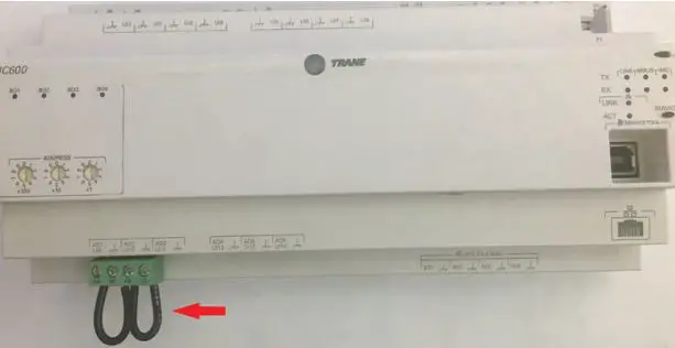
- If J1 and J2 are either both in place or both removed, the unit will operate as Thermostat controlled and Compressors will be enabled/disabled based on inputs UI1 – UI6 according to the wiring diagrams.
- If J1 is removed or cut and J2 remains in place, the unit will operate as Constant Volume (CV) and the compressors will be controlled to satisfy space temperature at local setpoint.
- If J1 is in place and J2 is removed or cut, the unit will operate as Variable Air Volume (VAV) and the compressors will be controlled to satisfy discharge air temperature at setpoint. A discharge air temperature sensor (10k Type II thermistor) is required for the unit to operate correctly. See wiring diagram.
- Once the new panel is installed, wiring reconnected and mode of operation set, restore power to the unit and verify correct operation.
- Because the refrigeration safeties were rewired through a relay and UC monitoring, each safety should be checked for wiring accuracy. Circuit compressors will be locked out after three safety trips within a one-hour period. Power must be cycled off and on at the unit disconnect to reset the hard lockout.
- Pull wire on Circuit 1 High Pressure Cutout (4S1) and verify relay 7K8 relay denergizes, and circuit 1 compressor(s) shut down immediately.
- Pull wire on Circuit 1 Low Pressure Cutout (4S5) and verify relay 7K9 relay deenergizes, and circuit 1 compressor(s) shut down immediately.
- Pull wire on Circuit 2 High Pressure Cutout (4S2) and verify relay 7K10 relay deenergizes, and circuit 2 compressor(s) shut down immediately.
- Pull wire on Circuit 2 Low Pressure Cutout (4S6) and verify relay 7K11 deenergizes, and circuit 2 compressor(s) shut down immediately.
- Remaining split-system RAUJ will follow standard startup procedure.
Chiller
- Once the new panel is installed, wiring reconnected and mode of operation set, restore power to the unit and verify correct operation. Do not enable unit yet!
- Verify the Freeze Setpoint (Analog Value 10) is set to an appropriate value for the fluid type being used in the chiller. Default value is 36°F for straight water.
- Verify the Low Ambient Lockout Setpoint is set to the proper value. Default value is 40°F. This value may be adjusted lower if low ambient damper option is installed. Setpoint adjustment is accomplished by adjusting analog constant in the “Setpoints” program.
- Since the refrigeration safeties were re-wired through a relay and UC monitoring, each safety should be checked for wiring accuracy. Circuit compressors will be locked out after 3 safety trips within a 1- hour period. Power must be cycled off and on at the unit disconnect to reset the hard lockout.
- Pull wire on Circuit 1 High Pressure Cutout (4S1) and verify relay 7K8 relay deenergizes, and circuit 1 compressor(s) shut down immediately.
- Pull wire on Circuit 1 Low Pressure Cutout (4S5) and verify relay 7K9 relay deenergizes, and circuit 1 compressor(s) shut down immediately.
- Pull wire on Circuit 2 High Pressure Cutout (4S2) and verify relay 7K10 relay deenergizes, and circuit 2 compressor(s) shut down immediately.
- Pull wire on Circuit 2 Low Pressure Cutout (4S6) and verify relay 7K11 deenergizes, and circuit 2 compressor(s) shut down immediately.
- Enable Circulating pump and verify 7K1 relay energizes. If 7K1 does not energize, verify all field installed safeties (flow switch, freezestat, motor overloads, etc.) are not tripped and wired properly.
- After a few moments the Tracer UC600, Cool Calc should start ramping up and enabling compressors. The Cool Calc P-Gain (Analog Value 3) may need to be adjusted based on water flow, chiller load, to avoid excessive cycling or over/undershooting setpoint.
- Remaining chiller startup will follow standard RAUJ startup procedure.
Object Data Points List
20 to 30T (AHU)
| Instance | Object Name | Point Reference | Read/Write | Description |
| Analog Inputs | ||||
| 1 | Discharge Air Temperature | UI12.analogValue | Read | Field Installed |
| 2 | Space Temperature Local | UI13.analogValue | Read | Field Installed |
| 3 | Space Temperature Setpoint Local | UI14.analogValue | Read | Field Installed |
| 4 | Outdoor Air Temperature | UI11.analogValue | Read | |
| Analog Values | ||||
| 1 | Active CoolCoil Control Sensor | Read | ||
| 2 | Active CoolCoil Control Setpoint | Read | ||
| 3 | Cooling Capacity Request TC | Read | ||
| 4 | Cooling Capacity Status | Read | ||
| 5 | Cooling PID Maximum Value | Read | ||
| 6 | Cooling PID Output | Read | ||
| 7 | Cooling Stages Requested TC | Read | ||
| 8 | Discharge Air Cooling Setpoint BAS | Read/Write | Default: 55°F Range: 50-125°F | |
| 9 | Discharge Air Cooling Setpoint Max BAS | Read/Write | Default: 65° Range: 50-85°F | |
| 10 | Discharge Air Temperature Setpoint Active | Read | ||
| 11 | Discharge Air Temperature Setpoint BAS | Read/Write | Default: 65°F Range: 50-120°F | |
| 12 | Discharge Air Temperature Setpoint Local | Read/Write | Default: 70°F Range: 50-120°F | |
| 13 | Local Setpoint High Limit | Read/Write | Default: 80°F Range: 60-90°F | |
| 14 | Local Setpoint Low Limit | Read/Write | Default: 65° Range: 45-75°F | |
| 15 | Occupied Cooling Setpoint | Read/Write | Default: 72° | |
| 16 | Occupied Heating Setpoint | Read/Write | Default: 68°F | |
| 17 | Occupied Offset | Read/Write | Default: 2°F Range: 0-18°F | |
| 18 | Occupied Standby Offset | Read/Write | Default: 4°F Range: 0-18°F | |
| 19 | Optional CoolCoil Control Command | Read | ||
| 20 | Space Temperature Active | Read | ||
| 21 | Space Temperature BAS | Read | ||
| 22 | Space Temperature Setpoint Active | Read | ||
| 23 | Space Temperature Setpoint BAS | Read/Write | Default: 70°F Range: 45-95°F | |
| 24 | Unoccupied Cooling Setpoint | Read/Write | Default: 80°F | |
| 25 | Unoccupied Heating Setpoint | Read/Write | Default: 60°F | |
| 26 | Cooling Capacity Request CV | Read | ||
| 27 | Cooling Capacity Request VAV | Read | ||
| 28 | Cooling Stages Requested CV | Read | ||
| 29 | Cooling Stages Requested VAV | Read | ||
| 101 | Cool Control P-Gain | Read/Write | Default: 1.5 Range: 0.5-25 | |
| 102 | Discharge Air Temperature Setpoint P-Gain | Read/Write | Default: 4 Range: 0-10 | |
| 103 | Circuit 1 HPCO Fail Count | Read | ||
| 104 | Circuit 1 LPCO Fail Count | Read | ||
| Binary Inputs | ||||
| 1 | Supply Fan Status | UI8.binaryValue | Read | |
| 2 | Occupancy Status | UI7.binaryValue | Read | Field Installed |
| 3 | Constant Volume Mode Input | UI9.binaryValue | Read | |
| 4 | VAV Mode Input | UI10.binaryValue | Read | |
| 5 | Cool 1 Call | UI1.binaryValue | Read | Field Installed |
| 6 | Cool 2 Call | UI2.binaryValue | Read | Field Installed |
| 9 | Circuit 1 High Pressure Cutout | XM.30.1.UIO1.binaryValue | Read | |
| 10 | Circuit 1 Low Pressure Cutout | XM.30.1.UIO2.binaryValue | Read | |
| Binary Outputs | ||||
| 1 | Compressor 1A Command | BO1.binaryValue | Read | 3 Minute On 5 Minute Off |
| 2 | Compressor 1B Command | BO2.binaryValue | Read | 3 Minute On 5 Minute Off |
| Binary Values | ||||
| 1 | Active CoolCoil Control Sensor Failed | Read | ||
| 2 | Circuit 1 Lockout BAS | Read/Write | Default: Off | |
| 3 | Circuit 2 Lockout BAS | Read/Write | Default: Off | |
| 4 | Diagnostic: Space Temperature Source Failure | Read | ||
| 5 | Economizer Interlock OK | Read | ||
| 6 | Fan Latch | Read | ||
| 7 | Heat Cool Mode Active | Read | ||
| 8 | Mixed Air Low Limit Active | Read | ||
| 9 | Night Heat Cool | Read | ||
| 10 | Startup Delay Completed | Read | ||
| 11 | Cooling Enabled | Read | ||
| 12 | CV Mode Active | Read | ||
| 13 | VAV Mode Active | Read | ||
| 14 | Thermosat Mode Active | Read | ||
| 15 | Low OA Temp Cutout | Read | ||
| 16 | Compressor 1A Command CV | Read | ||
| 17 | Compressor 1B Command CV | Read | ||
| 18 | Compressor 1A Command TC | Read | ||
| 19 | Compressor 1B Command TC | Read | ||
| 20 | Compressor 1A Command VAV | Read/Write | Default: Off | |
| 21 | Compressor 1B Command VAV | Read/Write | Default: Off | |
| 32 | Circuit 1 Soft Lockout | Read | ||
| 33 | Circuit 1 Hard Lockout | Read | ||
| Multistate Values | ||||
Object Data Points List
| Instance | Object Name | Point Reference | Read/Write | Description |
|
1 |
DX Staging Status |
Read | 1: Normal 2: Start Interval Active 3: Shutdown Delay Active 4: Subtract Suspended | |
|
2 |
Heat Cool Mode Request |
Read | 1: Auto 2: Heat 3: Morning Warm-up 4: Cool 5: Night Purge 6: Pre Cool 7: Off 8: Test 9: Emergency Heat 10: Fan Only 11: Free Cool 12: Ice-Making 13: Maximum Heat 14: Economizer 15: Dehumidify 16: Calibrate | |
|
3 |
Heat Cool Mode Status |
Read | 1: Auto 2: Heat 3: Morning Warm-up 4: Cool 5: Night Purge 6: Pre Cool 7: Off 8: Test 9: Emergency Heat 10: Fan Only 11: Free Cool 12: Ice-Making 13: Maximum Heat 14: Economizer 15: Dehumidify 16: Calibrate | |
|
4 |
Occupancy Request |
Read/Write | 1: Occupied 2: Unoccupied 3: Occupied Bypass 4: Occupied Standby 5: Auto | |
|
5 |
Occupancy Status |
Read | 1: Occupied 2: Unoccupied 3: Occupied Bypass 4: Occupied Standby 5: Auto |
|
6 |
Unit Operation |
Read | 1: Thermostat 2: Constant Volume 3: None 4: Variable Volume 5: Thermostat | |
| 100 | Unit Information | Read | 1: Version: 1 2: CID: 464/471/491/498/630/1183/1185/1191/ |
40 to 60T (AHU)
| Instance | Object Name | Point Reference | Read/Write | Description |
| Analog Inputs | ||||
| 1 | Discharge Air Temperature | UI12.analogValue | Read | Field Installed |
| 2 | Space Temperature Local | UI13.analogValue | Read | Field Installed |
| 3 | Space Temperature Setpoint Local | UI14.analogValue | Read | Field Installed |
| 4 | Outdoor Air Temperature | UI11.analogValue | Read | |
| Analog Values | ||||
| 1 | Active CoolCoil Control Sensor | Read | ||
| 2 | Active CoolCoil Control Setpoint | Read | ||
| 3 | Cooling Capacity Request TC | Read | ||
| 4 | Cooling Capacity Status | Read | ||
| 5 | Cooling PID Maximum Value | Read | ||
| 6 | Cooling PID Output | Read | ||
| 7 | Cooling Stages Requested TC | Read | ||
| 8 | Discharge Air Cooling Setpoint BAS | Read/Write | Default: 55°F Range: 50-125°F | |
| 9 | Discharge Air Cooling Setpoint Max BAS | Read/Write | Default: 65° Range: 50-85°F | |
| 10 | Discharge Air Temperature Setpoint Active | Read | ||
| 11 | Discharge Air Temperature Setpoint BAS | Read/Write | Default: 65°F Range: 50-120°F | |
| 12 | Discharge Air Temperature Setpoint Local | Read/Write | Default: 70°F Range: 50-120°F | |
| 13 | Local Setpoint High Limit | Read/Write | Default: 80°F Range: 60-90°F | |
| 14 | Local Setpoint Low Limit | Read/Write | Default: 65° Range: 45-75°F | |
| 15 | Occupied Cooling Setpoint | Read/Write | Default: 72° | |
| 16 | Occupied Heating Setpoint | Read/Write | Default: 68°F | |
| 17 | Occupied Offset | Read/Write | Default: 2°F Range: 0-18°F | |
| 18 | Occupied Standby Offset | Read/Write | Default: 4°F Range: 0-18°F | |
| 19 | Optional CoolCoil Control Command | Read | ||
| 20 | Space Temperature Active | Read | ||
| 21 | Space Temperature BAS | Read | ||
| 22 | Space Temperature Setpoint Active | Read | ||
| 23 | Space Temperature Setpoint BAS | Read/Write | Default: 70°F Range: 45-95°F | |
| 24 | Unoccupied Cooling Setpoint | Read/Write | Default: 80°F | |
| 25 | Unoccupied Heating Setpoint | Read/Write | Default: 60°F | |
| 26 | Cooling Capacity Request CV | Read | ||
| 27 | Cooling Capacity Request VAV | Read | ||
| 28 | Cooling Stages Requested CV | Read | ||
| 29 | Cooling Stages Requested VAV | Read | ||
| 101 | Cool Control P-Gain | Read/Write | Default: 1.5 Range: 0.5-25 | |
| 102 | Discharge Air Temperature Setpoint P-Gain | Read/Write | Default: 4 Range: 0-10 | |
| 103 | Circuit 1 HPCO Fail Count | Read | ||
| 104 | Circuit 1 LPCO Fail Count | Read | ||
| 105 | Circuit 2 HPCO Fail Count | Read | ||
| 106 | Circuit 2 LPCO Fail Count | Read | ||
| Binary Inputs | ||||
| 1 | Supply Fan Status | UI8.binaryValue | Read | |
| 2 | Occupancy Status | UI7.binaryValue | Read | Field Installed |
| 3 | Constant Volume Mode Input | UI9.binaryValue | Read | |
| 4 | VAV Mode Input | UI10.binaryValue | Read | |
| 5 | Cool 1 Call | UI1.binaryValue | Read | Field Installed |
| 6 | Cool 2 Call | UI2.binaryValue | Read | Field Installed |
| 7 | Cool 3 Call | UI3.binaryValue | Read | Field Installed |
| 8 | Cool 4 Call | UI4.binaryValue | Read | Field Installed |
| 9 | Circuit 1 High Pressure Cutout | XM.30.1.UIO1.binaryValue | Read | |
| 10 | Circuit 1 Low Pressure Cutout | XM.30.1.UIO2.binaryValue | Read | |
| 11 | Circuit 2 High Pressure Cutout | XM.30.1.UIO3.binaryValue | Read | |
| 12 | Circuit 2 Low Pressure Cutout | XM.30.1.UIO4.binaryValue | Read | |
| Binary Outputs | ||||
| 1 | Compressor 1A Command | BO1.binaryValue | Read | 3 Minute On 5 Minute Off |
| 2 | Compressor 1B Command | BO2.binaryValue | Read | 3 Minute On 5 Minute Off |
| 3 | Compressor 1C Command | BO3.binaryValue | Read | 3 Minute On 5 Minute Off |
| 4 | Compressor 2A Command | BO4.binaryValue | Read | 3 Minute On 5 Minute Off |
| Binary Values | ||||
| 1 | Active CoolCoil Control Sensor Failed | Read | ||
| 2 | Circuit 1 Lockout BAS | Read/Write | Default: Off | |
| 3 | Circuit 2 Lockout BAS | Read/Write | Default: Off | |
| 4 | Diagnostic: Space Temperature Source Failure | Read | ||
| 5 | Economizer Interlock OK | Read | ||
| 6 | Fan Latch | Read | ||
| 7 | Heat Cool Mode Active | Read | ||
| 8 | Mixed Air Low Limit Active | Read | ||
| 9 | Night Heat Cool | Read | ||
| 10 | Startup Delay Completed | Read | ||
| 11 | Cooling Enabled | Read | ||
| 12 | CV Mode Active | Read | ||
| 13 | VAV Mode Active | Read | ||
| 14 | Thermosat Mode Active | Read | ||
| 15 | Low OA Temp Cutout | Read | ||
| 16 | Compressor 1A Command CV | Read | ||
| 17 | Compressor 1B Command CV | Read | ||
| 18 | Compressor 1A Command TC | Read | ||
| 19 | Compressor 1B Command TC | Read | ||
| 20 | Circuit 3 Lockout BAS | Read/Write | Default: Off | |
| 21 | Circuit 4 Lockout BAS | Read/Write | Default: Off | |
| 22 | Compressor 2A Command CV | Read | ||
| 23 | Compressor 2A Command TC | Read | ||
| 24 | Compressor 2B Command CV | Read | ||
| 25 | Compressor 2B Command TC | Read | ||
| 26 | Compressor 1A Command VAV | Read/Write | Default: Off | |
| 27 | Compressor 1B Command VAV | Read/Write | Default: Off | |
| 28 | Compressor 2A Command VAV | Read | ||
| 29 | Compressor 2B Command VAV | Read | ||
| 32 | Circuit 1 Soft Lockout | Read | ||
| 33 | Circuit 1 Hard Lockout | Read | ||
| 34 | Circuit 2 Soft Lockout | Read | ||
| 35 | Circuit 2 Hard Lockout | Read | ||
| Multistate Values | ||||
|
1 |
DX Staging Status |
Read | 1: Normal 2: Start Interval Active 3: Shutdown Delay Active 4: Subtract Suspended | |
|
2 |
Heat Cool Mode Request |
Read | 1: Auto 2: Heat 3: Morning Warm-up 4: Cool 5: Night Purge 6: Pre Cool 7: Off 8: Test 9: Emergency Heat 10: Fan Only 11: Free Cool 12: Ice-Making 13: Maximum Heat 14: Economizer 15: Dehumidify 16: Calibrate | |
|
3 |
Heat Cool Mode Status |
Read | 1: Auto 2: Heat 3: Morning Warm-up 4: Cool 5: Night Purge 6: Pre Cool 7: Off 8: Test 9: Emergency Heat 10: Fan Only 11: Free Cool 12: Ice-Making 13: Maximum Heat 14: Economizer 15: Dehumidify 16: Calibrate | |
|
4 |
Occupancy Request |
Read/Write | 1: Occupied 2: Unoccupied 3: Occupied Bypass 4: Occupied Standby 5: Auto | |
|
5 |
Occupancy Status |
Read | 1: Occupied 2: Unoccupied 3: Occupied Bypass 4: Occupied Standby 5: Auto | |
|
6 |
Unit Operation |
Read | 1: Thermostat 2: Constant Volume 3: None 4: Variable Volume 5: Thermostat | |
| 100 | Unit Information | Read | 1: Version: 1 2: CID: 464/471/491/498/630/1183/1185/1191/ |
80 to 120T (AHU)
| Instance | Object Name | Point Reference | Read/Write | Description |
| Analog Inputs | ||||
| 1 | Discharge Air Temperature | UI12.analogValue | Read | Field Installed |
| 2 | Space Temperature Local | UI13.analogValue | Read | Field Installed |
| 3 | Space Temperature Setpoint Local | UI14.analogValue | Read | Field Installed |
| 4 | Outdoor Air Temperature | UI11.analogValue | Read | |
| Analog Values | ||||
| 1 | Active CoolCoil Control Sensor | Read | ||
| 2 | Active CoolCoil Control Setpoint | Read | ||
| 3 | Cooling Capacity Request TC | Read | ||
| 4 | Cooling Capacity Status | Read | ||
| 5 | Cooling PID Maximum Value | Read | ||
| 6 | Cooling PID Output | Read | ||
| 7 | Cooling Stages Requested TC | Read | ||
| 8 | Discharge Air Cooling Setpoint BAS | Read/Write | Default: 55°F Range: 50-125°F | |
| 9 | Discharge Air Cooling Setpoint Max BAS | Read/Write | Default: 65° Range: 50-85°F | |
| 10 | Discharge Air Temperature Setpoint Active | Read | ||
| 11 | Discharge Air Temperature Setpoint BAS | Read/Write | Default: 65°F Range: 50-120°F | |
| 12 | Discharge Air Temperature Setpoint Local | Read/Write | Default: 70°F Range: 50-120°F | |
| 13 | Local Setpoint High Limit | Read/Write | Default: 80°F Range: 60-90°F | |
| 14 | Local Setpoint Low Limit | Read/Write | Default: 65° Range: 45-75°F | |
| 15 | Occupied Cooling Setpoint | Read/Write | Default: 72° | |
| 16 | Occupied Heating Setpoint | Read/Write | Default: 68°F | |
| 17 | Occupied Offset | Read/Write | Default: 2°F Range: 0-18°F | |
| 18 | Occupied Standby Offset | Read/Write | Default: 4°F Range: 0-18°F | |
| 19 | Optional CoolCoil Control Command | Read | ||
| 20 | Space Temperature Active | Read | ||
| 21 | Space Temperature BAS | Read | ||
| 22 | Space Temperature Setpoint Active | Read | ||
| 23 | Space Temperature Setpoint BAS | Read/Write | Default: 70°F Range: 45-95°F | |
| 24 | Unoccupied Cooling Setpoint | Read/Write | Default: 80°F | |
| 25 | Unoccupied Heating Setpoint | Read/Write | Default: 60°F | |
| 26 | Cooling Capacity Request CV | Read | ||
| 27 | Cooling Capacity Request VAV | Read | ||
| 28 | Cooling Stages Requested CV | Read | ||
| 29 | Cooling Stages Requested VAV | Read | ||
| 101 | Cool Control P-Gain | Read/Write | Default: 1.5 Range: 0.5-25 | |
| 102 | Discharge Air Temperature Setpoint P-Gain | Read/Write | Default: 4 Range: 0-10 | |
| 103 | Circuit 1 HPCO Fail Count | Read | ||
| 104 | Circuit 1 LPCO Fail Count | Read | ||
| 105 | Circuit 2 HPCO Fail Count | Read | ||
| 106 | Circuit 2 LPCO Fail Count | Read | ||
| Binary Inputs | ||||
| 1 | Supply Fan Status | UI8.binaryValue | Read | |
| 2 | Occupancy Status | UI7.binaryValue | Read | Field Installed |
| 3 | Constant Volume Mode Input | UI9.binaryValue | Read | |
| 4 | VAV Mode Input | UI10.binaryValue | Read | |
| 5 | Call 1 Call | UI1.binaryValue | Read | Field Installed |
| 6 | Call 2 Call | UI2.binaryValue | Read | Field Installed |
| 7 | Call 3 Call | UI3.binaryValue | Read | Field Installed |
| 8 | Call 4 Call | UI4.binaryValue | Read | Field Installed |
| 9 | Call 5 Call | UI5.binaryValue | Read | Field Installed |
| 10 | Call 6 Call | UI6.binaryValue | Read | Field Installed |
| 11 | Circuit 1 High Pressure Cutout | XM.30.1.UIO1.binaryValue | Read | |
| 12 | Circuit 1 Low Pressure Cutout | XM.30.1.UIO2.binaryValue | Read | |
| 13 | Circuit 2 High Pressure Cutout | XM.30.1.UIO3.binaryValue | Read | |
| 14 | Circuit 2 Low Pressure Cutout | XM.30.1.UIO4.binaryValue | Read | |
| Binary Outputs | ||||
| 1 | Compressor 1A Command | BO1.binaryValue | Read | 3 Minute On 5 Minute Off |
| 2 | Compressor 1B Command | BO2.binaryValue | Read | 3 Minute On 5 Minute Off |
| 3 | Compressor 1C Command | BO3.binaryValue | Read | 3 Minute On 5 Minute Off |
| 4 | Compressor 2A Command | BO4.binaryValue | Read | 3 Minute On 5 Minute Off |
| 5 | Compressor 2B Command | XM30.BO1.binaryValue | Read | 3 Minute On 5 Minute Off |
| 6 | Compressor 2C Command | XM30.BO2.binaryValue | Read | 3 Minute On 5 Minute Off |
| Binary Values | ||||
| 1 | Active CoolCoil Control Sensor Failed | Read | ||
| 2 | Circuit 1 Lockout BAS | Read/Write | Default: Off | |
| 3 | Circuit 2 Lockout BAS | Read/Write | Default: Off | |
| 4 | Diagnostic: Space Temperature Source Failure | Read | ||
| 5 | Economizer Interlock OK | Read | ||
| 6 | Fan Latch | Read | ||
| 7 | Heat Cool Mode Active | Read | ||
| 8 | Mixed Air Low Limit Active | Read | ||
| 9 | Night Heat Cool | Read | ||
| 10 | Startup Delay Completed | Read | ||
| 11 | Cooling Enabled | Read | ||
| 12 | CV Mode Active | Read | ||
| 13 | VAV Mode Active | Read | ||
| 14 | Thermosat Mode Active | Read | ||
| 15 | Low OA Temp Cutout | Read | ||
| 16 | Compressor 1A Command CV | Read | ||
| 17 | Compressor 1B Command CV | Read | ||
| 18 | Compressor 1A Command TC | Read | ||
| 19 | Compressor 1B Command TC | Read | ||
| 20 | Circuit 3 Lockout BAS | Read/Write | Default: Off | |
| 21 | Circuit 4 Lockout BAS | Read/Write | Default: Off | |
| 22 | Compressor 1C Command CV | Read | ||
| 23 | Compressor 1C Command TC | Read | ||
| 24 | Compressor 2A Command CV | Read | ||
| 25 | Compressor 2A Command TC | Read | ||
| 26 | Compressor 5 Lockout BAS | Read/Write | Default: Off | |
| 27 | Compressor 6 Lockout BAS | Read/Write | Default: Off | |
| 28 | Compressor 2B Command TC | Read | ||
| 29 | Compressor 2B Command CV | Read | ||
| 30 | Compressor 2C Command TC | Read | ||
| 31 | Compressor 2C Command CV | Read | ||
| 32 | Circuit 1 Soft Lockout | Read | ||
| 33 | Circuit 1 Hard Lockout | Read | ||
| 34 | Circuit 2 Soft Lockout | Read | ||
| 35 | Circuit 2 Hard Lockout | Read | ||
| 36 | Compressor 1A Command VAV | Read | ||
| 37 | Compressor 1B Command VAV | Read | ||
| 38 | Compressor 1C Command VAV | Read | ||
| 39 | Compressor 2A Command VAV | Read | ||
| 40 | Actuator Type | Read | ||
| 41 | Compressor 2B Command VAV | Read | ||
| 42 | Compressor 2C Command VAV | Read | ||
| Multistate Values | ||||
|
1 |
DX Staging Status |
Read | 1: Normal 2: Start Interval Active 3: Shutdown Delay Active 4: Subtract Suspended | |
|
2 |
Heat Cool Mode Request |
Read | 1: Auto 2: Heat 3: Morning Warm-up 4: Cool 5: Night Purge 6: Pre Cool 7: Off 8: Test 9: Emergency Heat 10: Fan Only 11: Free Cool 12: Ice-Making 13: Maximum Heat 14: Economizer 15: Dehumidify 16: Calibrate | |
|
3 |
Heat Cool Mode Status |
Read | 1: Auto 2: Heat 3: Morning Warm-up 4: Cool 5: Night Purge 6: Pre Cool 7: Off 8: Test 9: Emergency Heat 10: Fan Only 11: Free Cool 12: Ice-Making 13: Maximum Heat 14: Economizer 15: Dehumidify 16: Calibrate | |
|
4 |
Occupancy Request |
Read/Write | 1: Occupied 2: Unoccupied 3: Occupied Bypass 4: Occupied Standby 5: Auto | |
|
5 |
Occupancy Status |
Read | 1: Occupied 2: Unoccupied 3: Occupied Bypass 4: Occupied Standby 5: Auto | |
|
6 |
Unit Operation |
Read | 1: Thermostat 2: Constant Volume 3: None 4: Variable Volume 5: Thermostat | |
| 100 | Unit Information | Read | 1: Version: 1 2: CID: 464/471/491/498/630/1183/1185/1191/ |
20 to 30T (Chiller)
| Instance | Object Name | Point Reference | Read/Write | Description |
| Analog Inputs | ||||
| 1 | Outdoor Air Temperature | UI2.analogValue | Read | |
| 2 | Leaving Water Temperature | UI3.analogValue | Read | Field Installed |
| Analog Values | ||||
| 1 | Leaving Water Temp Setpoint BAS | Read/Write | ||
| 2 | Cool Calc | Read | ||
| 3 | Cool Calc P-gain | Read/Write | ||
| 4 | Circuit 1 HPCO Fail Count | Read | ||
| 5 | Circuit 1 LPCO Fail Count | Read | ||
| 6 | Circuit 2 HPCO Fail Count | Read | ||
| 7 | Circuit 2 LPCO Fail Count | Read | ||
| 10 | Freeze Setpoint | R/W | ||
| Binary Inputs | ||||
| 1 | Chiller Enable | UI1.binaryValue | Read | |
| 9 | Circuit 1 High Pressure Cutout | XM.30.2.UIO1.binaryValue | Read | |
| 10 | Circuit 1 Low Pressure Cutout | XM.30.2.UIO2.binaryValue | Read | |
| Binary Outputs | ||||
| 1 | Compressor 1A Command | BO1 (Relay).binaryValue | Read | 3 Minute On 5 Minute Off |
| 2 | Compressor 1B Command | BO2 (Relay).binaryValue | Read | 3 Minute On 5 Minute Off |
| Binary Values | ||||
| 1 | Chiller Disable BAS | Read/Write | On=Chiller Disabled | |
| 2 | Low Ambient Lockout | Read | ||
| 3 | High Ambient Lockout | Read | ||
| 4 | Warning-Low Fluid Temp | Read | ||
| 5 | Circuit 1 Hard Lockout | Read | ||
| 6 | Circuit 1 Soft Lockout | Read | ||
| 7 | Circuit 2 Hard Lockout | Read | ||
| 8 | Circuit 2 Soft Lockout | Read | ||
| 9 | Compressor 1 Call | Read | ||
| 10 | Compressor 2 Call | Read | ||
| 15 | Freeze Avoidance Lockout 1 | Read | ||
| 16 | Freeze Avoidance Lockout 2 | Read | ||
40 to 60T (Chiller)
| Instance | Object Name | Point Reference | Read/Write | Description |
| Analog Inputs | ||||
| 1 | Outdoor Air Temperature | UI2.analogValue | Read | |
| 2 | Leaving Water Temperature | UI3.analogValue | Read | Field Installed |
| Analog Values | ||||
| 1 | Leaving Water Temp Setpoint BAS | Read/Write | ||
| 2 | Cool Calc | Read | ||
| 3 | Cool Calc P-gain | Read/Write | ||
| 4 | Circuit 1 HPCO Fail Count | Read | ||
| 5 | Circuit 1 LPCO Fail Count | Read | ||
| 6 | Circuit 2 HPCO Fail Count | Read | ||
| 7 | Circuit 2 LPCO Fail Count | Read | ||
| 10 | Freeze Setpoint | Read | ||
| Binary Inputs | ||||
| 1 | Chiller Enable | UI1.binaryValue | Read | |
| 9 | Circuit 1 High Pressure Cutout | XM.30.2.UIO1.binaryValue | Read | |
| 10 | Circuit 1 Low Pressure Cutout | XM.30.2.UIO2.binaryValue | Read | |
| 11 | Circuit 2 High Pressure Cutout | XM.30.2.UIO3.binaryValue | Read | |
| 12 | Circuit 2 Low Pressure Cutout | XM.30.2.UIO4.binaryValue | Read | |
| Binary Outputs | ||||
| 1 | Compressor 1A Command | BO1 (Relay).binaryValue | Read | 3 Minute On 5 Minute Off |
| 2 | Compressor 1B Command | BO2 (Relay).binaryValue | Read | 3 Minute On 5 Minute Off |
| 3 | Compressor 2A Command | BO3 (Relay).binaryValue | Read | 3 Minute On 5 Minute Off |
| 4 | Compressor 2B Command | BO4 (Relay).binaryValue | Read | 3 Minute On 5 Minute Off |
| Binary Values | ||||
| 1 | Chiller Disable BAS | Read/Write | On=Chiller Disabled | |
| 2 | Low Ambient Lockout | Read | ||
| 3 | High Ambient Lockout | Read | ||
| 4 | Warning-Low Fluid Temp | Read | ||
| 5 | Circuit 1 Hard Lockout | Read | ||
| 6 | Circuit 1 Soft Lockout | Read | ||
| 7 | Circuit 2 Hard Lockout | Read | ||
| 8 | Circuit 2 Soft Lockout | Read | ||
| 9 | Compressor 1 Call | Read | ||
| 10 | Compressor 2 Call | Read | ||
| 11 | Compressor 3 Call | Read | ||
| 12 | Compressor 4 Call | Read | ||
| 15 | Freeze Avoidance Lockout 1 | Read | ||
| 16 | Freeze Avoidance Lockout 2 | Read | ||
80 to 120T (Chiller)
| Instance | Object Name | Point Reference | Read/Write | Description |
| Analog Inputs | ||||
| 1 | Outdoor Air Temperature | UI2.analogValue | Read | |
| 2 | Leaving Water Temperature | UI3.analogValue | Read | Field Installed |
| Analog Values | ||||
| 1 | Leaving Water Temp Setpoint BAS | Read/Write | ||
| 2 | Cool Calc | Read | ||
| 3 | Cool Calc P-gain | Read/Write | ||
| 4 | Circuit 1 HPCO Fail Count | Read | ||
| 5 | Circuit 1 LPCO Fail Count | Read | ||
| 6 | Circuit 2 HPCO Fail Count | Read | ||
| 7 | Circuit 2 LPCO Fail Count | Read | ||
| 10 | Freeze Setpoint | R/W | ||
| Binary Inputs | ||||
| 1 | Chiller Enable | UI1.binaryValue | Read | |
| 9 | Circuit 1 High Pressure Cutout | XM.30.2.UIO1.binaryValue | Read | |
| 10 | Circuit 1 Low Pressure Cutout | XM.30.2.UIO2.binaryValue | Read | |
| 11 | Circuit 2 High Pressure Cutout | XM.30.2.UIO3.binaryValue | Read | |
| 12 | Circuit 2 Low Pressure Cutout | XM.30.2.UIO4.binaryValue | Read | |
| Binary Outputs | ||||
| 1 | Compressor 1A Command | BO1 (Relay).binaryValue | Read | 3 Minute On 5 Minute Off |
| 2 | Compressor 1B Command | BO2 (Relay).binaryValue | Read | 3 Minute On 5 Minute Off |
| 3 | Compressor 2A Command | BO3 (Relay).binaryValue | Read | 3 Minute On 5 Minute Off |
| 4 | Compressor 2B Command | BO4 (Relay).binaryValue | Read | 3 Minute On 5 Minute Off |
| 5 | Compressor 1C Command | XM.32.1.BO1 (Relay).binaryValue | Read | 3 Minute On 5 Minute Off |
| 6 | Compressor 2C Command | XM.32.1.BO2 (Relay).binaryValue | Read | 3 Minute On 5 Minute Off |
| Binary Values | ||||
| 1 | Chiller Disable BAS | Read/Write | On=Chiller Disabled | |
| 2 | Low Ambient Lockout | Read | ||
| 3 | High Ambient Lockout | Read | ||
| 4 | Warning-Low Fluid Temp | Read | ||
| 5 | Circuit 1 Hard Lockout | Read | ||
| 6 | Circuit 1 Soft Lockout | Read | ||
| 7 | Circuit 2 Hard Lockout | Read | ||
| 8 | Circuit 2 Soft Lockout | Read | ||
| 9 | Compressor Call 1 | Read | ||
| 10 | Compressor Call 2 | Read | ||
| 11 | Compressor Call 3 | Read | ||
| 12 | Compressor Call 4 | Read | ||
| 13 | Compressor Call 5 | Read | ||
| 14 | Compressor Call 6 | Read | ||
| 15 | Freeze Avoidance Lockout 1 | Read | ||
| 16 | Freeze Avoidance Lockout 2 | Read | ||
Trane – by Trane Technologies (NYSE: TT), a global climate innovator – creates comfortable, energy-efficient indoor environments for commercial and residential applications. For more information, please visit trane.com or tranetechnologies.com.
Trane has a policy of continuous product and product data improvement and reserves the right to change design and specifications without notice. We are committed to using environmentally conscious print practices.


