![]() PNI GreenHouse SC3100B 3KW
PNI GreenHouse SC3100B 3KW
Invertor solar
User Manual
GreenHouse SC3100B 3KW Inverter Solar
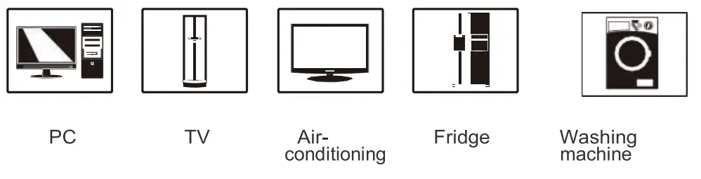
Appliances
WARNING!
This manual contains important instructions for all Inverter/Charger models that shall be followed during installation and maintenance of theinverter.
The following cases are not within the scope of warranty
- Out of warranty.
- Series number was changed or lost.
- Battery capacity was declined or external damaged.
- Inverter was damaged caused of transport shift, remissness, ect external factor
- Inverter was damaged caused of irresistible natural disasters.
- Not in accordance with the electrical power supply conditions or operate environment caused damage.
General Precautions
Before using it, read all instructions and markings:
(1) inverter (2) battery (3) user manual
CAUTION:
- To reduce r i s k of injury, charge only lead-acid rechargeable batteries . If customer use flooded batteries, batteries must be maintained regularly. Other battery types may cause damage and inJury .
- Do not expose it to rain, snow or any type liquids. Inverters are designed for indoor use.
- Do not disassemble it. Take i t to qualified service center when service or repair is needed.
- To prevent the risk of electric shock, disconnect all wiring before attempting any maintenance or cleaning. Only turning off the unit will not reduce the risk.
WARNING:
- Provide ventilation from the battery compartment to outdoors. The battery enclosure should be designed to prevent accumulation and concentration of hydrogen gas at the top of the compartment.
- NEVER charge a frozen battery and connect such 12V/24V/48V batteries toinverter.
- Input/output AC wiring mustn’t be less than 12AWG and not rated for 75°C or higher. Battery cable mustn’t be rated for 75°C or higher and should be no less than 4AWG /6AWG gauge.
- Pay special attention when working with metal tools around batteries. Batteries short-circu’i ng could cause an explosion.
- Read the battery installation and maintenance instructions carefully before operating.
Personnel Precautions
- Better to prepare plenty of fresh water and soap nearby in case battery acid contacts skin, clothing oreyes.
- Avoid touching eyes while working near batteries.
- NEVER smoke or allow a spark or flame near batteries.
- Remove personal metal items such as rings, bracelets, necklaces, and watches when working with batteries. Batteries may provide heavy short-circuit current, which would be enough to make metal melt and causes severe burn.
- If a remote or automatic generator start system is used, disable the automatic starting circuit or disconnect the generator to prevent accident during servicing
Introduction
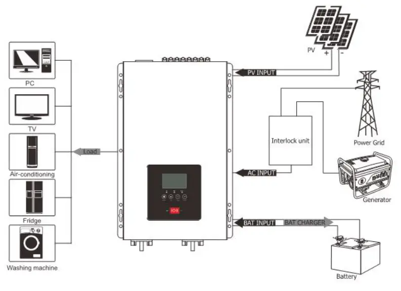
This series is very economical pure sine wave inverter, AC charger inbuilt, from 20A to 60A; Solar/ AC priority is configurable. When setting solar priority, solar will charge batteries as first priority, and AC can also charge batteries when solar charger current is too low, in this way system charge is optimized best. It enables inverter to operate with all kinds of home appliances.
Features:
- Pure sine wave output
- Friendly user interface
- 3 Steps charging
- MFD (multi-function display)
- Overload and short-circuit protection
- Set charging voltage/charging current.
- Battery low voltage shutdown point can be set to 10/10.5/11V ( x2 for 24V systems)
- Power-save mode
- Set utility priority/ Battery priority
- Set utility input wide/narrow range
- Inverter voltage can be set to 120V:110V/115V/120V 220V:220V/230V/240V
- Inverter frequency can be set to 50/60Hz
- Set utility charging on/off switch
- 80A MPPT charger
LCD Panel Description
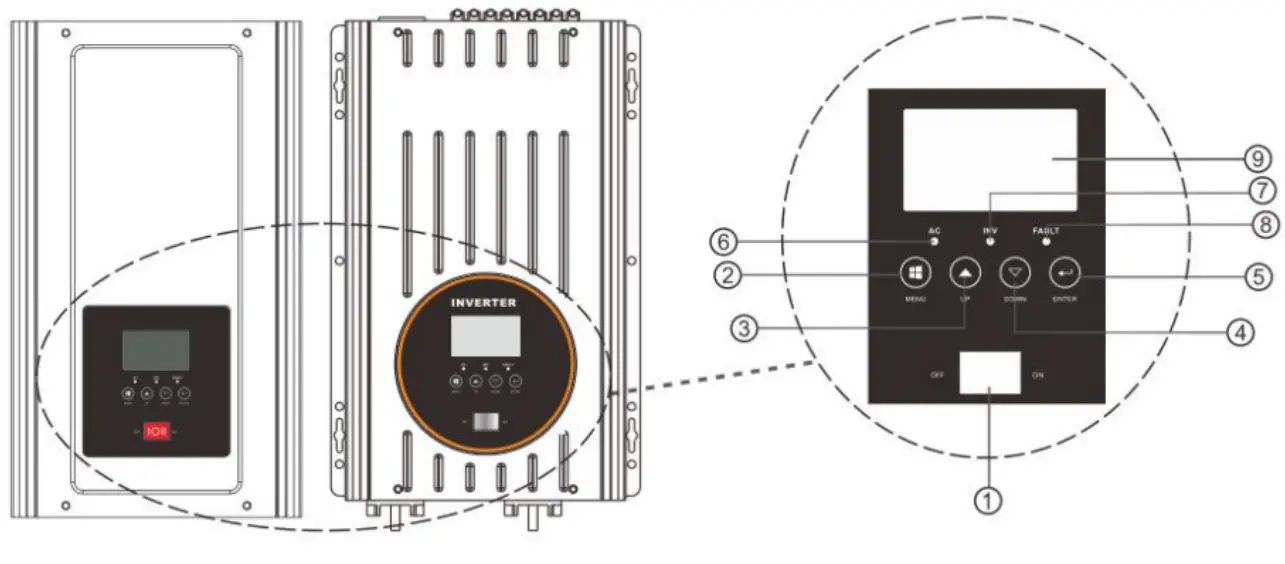
- Switch ON/OFF: POWER ON/OFF Switch
- MENU
- UP
- DOWN
- ENTER
- ACLED
- INVLED
- FAULT
- LCD
AC terminal panel printing description.
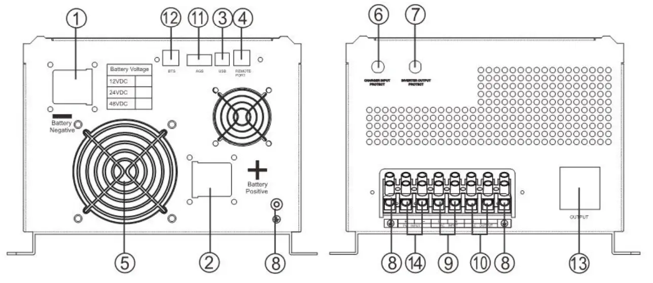
| 1 . BAT- 2. BAT+ 3. USB 4. Remote port 5. FAN 6. Charger input protect 7. Inverter output protect | 8. GND 9. ACinput 10. AC output 11. AGS 11. B T S 13. AC Output 10A(MAX) 14. PV input |
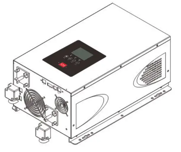
Installation
Unpacking and inspection
Before installation, please inspect whole unit . Be sure that nothing inside the package is damaged. You should have received the following items inside ofpackage.
| User manual X1 | Software CD X1 (Optional) |
| Communication cable X 1 | Battery cables (RED/BLACK) X 2 (Optional) |
Preparation
Before connecting all wirings, please take off bottom cover by removing eight screws as shown below:
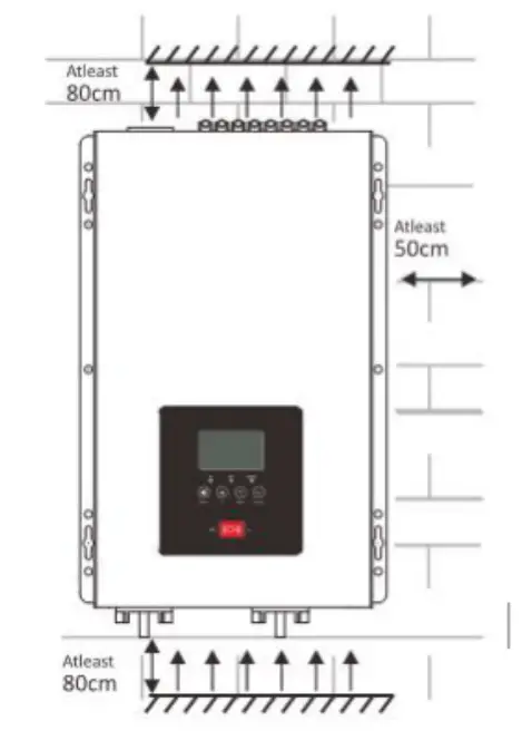
Mounting the Unit
Consider the following points before selecting where to install:
- Do not mount the inverter on flammable construction materials.
- Mount on a solid surface.
- Install this inverter at eye level in order to read the LCD display clearly. For proper air circulation to dissipate heat, require a clearance about 50 cm to the side and 80 cm above and below the unit.
- The ambient temperature should be between 0°C and 40°C to ensure optimal operation.
- The recommended installation position is to be adhered to the wall vertically.
- Be sure to keep other objects and surfaces as shown in the diagram to guarantee sufficient heat dissipation and to have enough space or removing wires.
DC Wiring Suggestion
It is suggested to keep battery bank as close as possible to inverter. battery cable length Im is suggested.
Please find following minimum wire size. If DC cable longer than 1 m, please use thicker battery cables to bear power current going though.
| Model | Battery Voltage Type | Wire Type |
| 3KW | 24VDC | 3AWG |
Please connect cable size thicker enough, or connect several combined thin cables together to be same strong. Battery bank should be kept close to inverter; The shorter and thicker cables, the better the system performance.
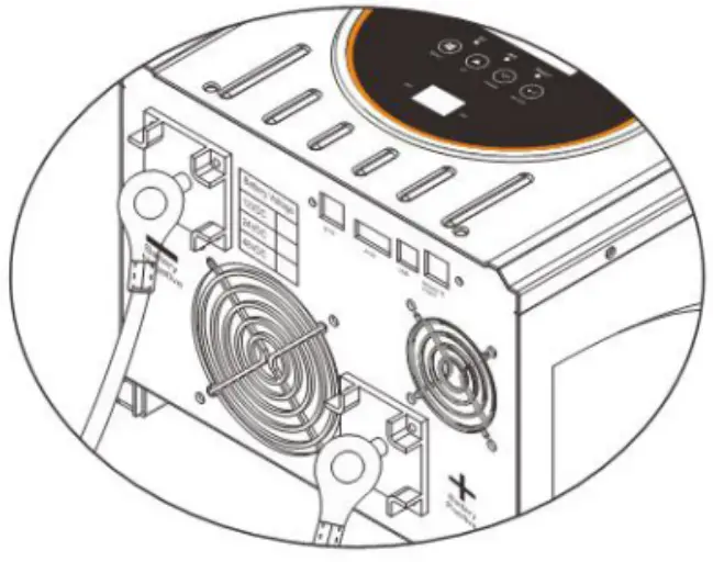
Please follo w battery connection steps below:
Assemble battery ring terminal.
Connect all battery packs as units requires.
Battery cable and terminal size suggestion:
It’s suggested to connect at least 100Ah capacity battery pack for IKW-3KW models , at least 200Ah for 4KW-6KW models.
It is mandatory t o instal a DC breaker/ disconnector between inverter and batteries.
NOTE: Please only use sealed lead acid battery or sealed GEL/AGM lead-acid battery.
Insert the ring terminal of battery cable into inverter to battery connector, make sure the bolts are tightened with torque of 2-3Nm. Pay special attention to battery back and inverter are connected rightly, also ring terminals are tightly screwed to the battery terminals.
![]() WARNING: Shock Hazard
WARNING: Shock Hazard
Installation with special care is required due to high battery pack voltage![]() CAUTIONI!I Do not place anything between the flat part of the inverter terminal and the ring terminal. Otherwise, overheating mayoccur.
CAUTIONI!I Do not place anything between the flat part of the inverter terminal and the ring terminal. Otherwise, overheating mayoccur.
CAUTION!! Do not apply antioxidant substance on the terminals before terminals are connected tightly.
CAUTIONI! Before making the final DC connection or closing DC breaker/ disconnector, be sure positive (+) must be connected to positive(+) and negative(-) must be connected to negative(-).
AC Input/Output Connection
CAUTIONII Before connecting to AC input power source, please install a separate AC breaker between inverter and AC input power source. This will ensure inverter can be disconnected safely during maintenance and fully protected from over current of AC input. Suggestion AC breaker: 30A for 1KW-3KW, 40A for 4KW-6KW.
CAUTION!!! Please don’t connect the output wring to “Grid” terminal or connect the grid wring to the “Load” terminal.
WARNINGI All wiring must be performed by a qualified personnel.
WARNING! i t ‘ s very important to use appropriate cable for Grid connection for system safety and efficient operation . Toreduce injury risk, please use the proper suggested cable size as below.
AC Wiring
We recommend using 10-S5AWG wire to connect AC terminal block. There are 3 different ways to connect AC wire to terminal block. All wirings are CE compliant, call our tech support if you are not sure about how to wire any part of your inverter.
| AC Wiring Input: Live line +Neutral + Ground Output : Live line +Neutral +Ground | 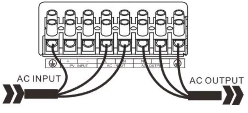 |
Suggested cable requirement for AC wires
| Model | Gauge | Torque Value |
| 1-3KW | 12AWG | 1.2-1.6Nm |
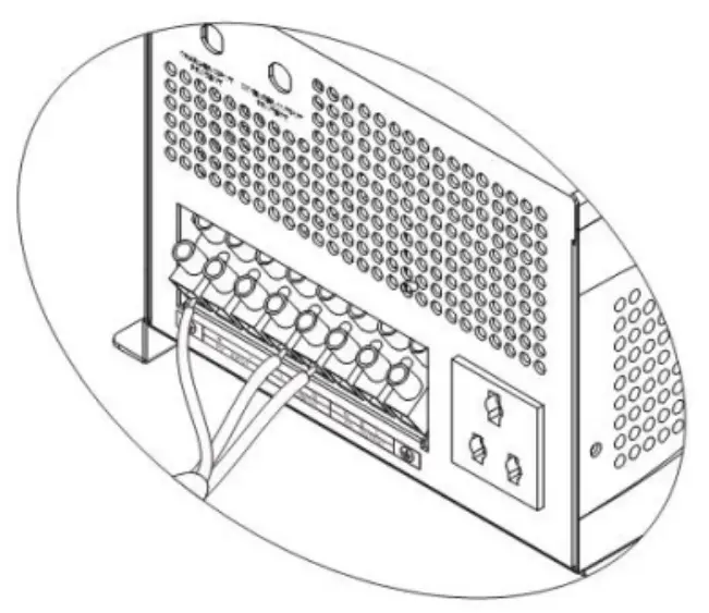
Please follow below steps to implement Load/Grid connection:
‘Before making Load/Grid connection, be sure to open DC protector or disconnector first .
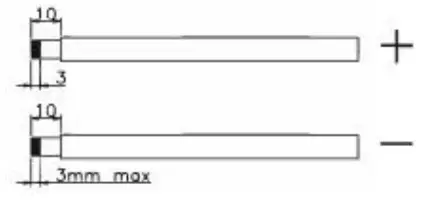
‘Remove insulation sleeve 10mm for six conductors. And shorten phase Land neutral conductor N 3mm.
‘Insert grid wires according to polarities indicated on terminal block and tighten the terminal screws. Be Sure to connect PE protective conductor(![]() )pfirst.
)pfirst.
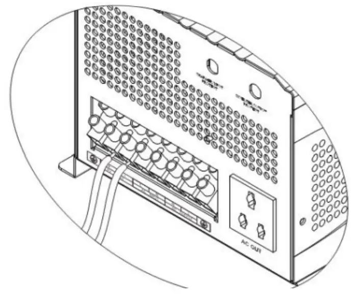
AC INPUT Connection![]() . Ground (yellow-green)
. Ground (yellow-green)
L: LINE (brown or black)
N: Neutral (blue)
![]() WARNING:
WARNING:
Be sure that AC power source is disconnected before hard-wire it to the unit.
– Then, insert Load wires according to polarities indicated on terminal block and tighten terminal screws. Be sure to connect PE protective conductor(![]() ) first
) first
AC OUTPUT Connection
@ Ground (yellow-green)
L LINE (brown or black)
N Neutral (blue)
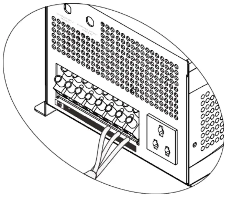
-Make sure the wires are securely connected.
CAUTION: Appliances such as air conditioner are required at least 2-3 minutes to restart because it’s required to have enough time to balance refrigerant gas inside of circuits. If a power shortage occurs and recovers in a short time, it will cause damage to your connected appliances. To prevent this kind of damage, please check manufacturer of air conditioner if it’s equipped with time-delay function before installation. Otherwise, this inverter will be triggered overload fault and cut off output to protect your appliance but sometimes it still causes internal damage to the air conditioner.
PV Connection
Please follow below steps to implement PV module connection:
- Remove insulation sleeve 10 mm for positive and negative conductors .

- Check correct polarity of connection cable from PV module and PV input conductors. Then connect positive pole (+)of connection cab e to positive pole (+)of PV inputconnector. Connect negative pole(-) ofconnection cable to negative (-) of PV input connector.

- Make sure the wires are securely connected
Operation
Operation key instructions:
- Switch button to control the machine On and off.
- There are four buttons: MENU, UP, DOWN, ENTER.
- Via UP and DOWN can check the various parameters display.
- Long press MENU t o enter the setting menu page, MENU and ENTER turn over the menu page, UP and DOWN to set the parameters. After setting, long press ENTER 2s to exit, except the inverter frequency and inverter voltage parameters, The setting parameters are notsavedtothe EEPROM. TheEEPROMissavedonly whenthe parameters are normally set. (To ensure that the parameters can be successfully saved, so every time after setting the parameters need restart the machine).
Setting key instructions:
| MENU | Function key | Function description | |
| 1 | Battery/AC priority setting | Utility priority(default) | If choice UTI, the inverter work in AC model until AC cut off or over the AC range. |
| Battery priority
| The inverter work in AC model if battery less 20set value. The inverter work in DC model if battery more than 21set value continue 1min. | ||
| 2 | 110V Utility power range setting | vdE: Wide(default)
| If set Wide, the AC range 70-140V. |
| NRU: Narrow
| If set NRU, the AC range 90-140V. | ||
| 2 | 220V Utility power range setting | vdE: Wide(default)
| If set Wide, the AC range 140-270V. |
| NRU: Narrow
| If set NRU, the AC range 180-270V. | ||
| 3 | 120V Mode Inverter voltage setting | 110V(default)
| 110/115/120V |
| 220V Mode Inverter voltage setting | 220V(default)
| 220/230/240V | |
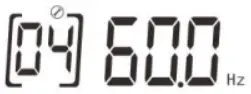
| 04 Inverter frequency setting | 50HZ(default)
| 60HZ
| |


| 13 | AC charging setting | Rated current(default)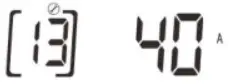 | Range of adjustment: 10A – Max |
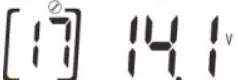
| 17 | Boost voltage setting | 14.1V(default).
| Range of adjustment 13.8-14.5V |
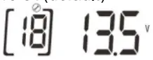
| 18 | Floating charging setting | 13.5V(default)
| Range of adjustment 13.5-13.7V |
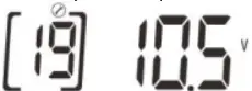
| 19 | Battery low voltage shutdown point setting | 10.5V(default)
| Range of adjustment 10-11V |
| 20 | SBU Battery low voltage power point | 11.5V(default)
| Range of adjustment 10.5-12.0V If you choice SBU, when the battery voltage less than value, the inverter will work in AC model |
| 21 | SBU Battery high voltage inverter point | 13.5V(default)
| Range of adjustment 13V-14.0V If you choice SBU, when the battery voltage more than value continue 1min, the inverte will work in DC model. |
| 23 | LCD back light settings | LCD ON
| The LCD back light on. |
| LCD OFF(default)
| Press any button to light up continue 1min. | ||
| 24 | Buzzer switch settings | Buzzer ON(default)
| Buzzer OFF
|
| 27 | Save mode switch settings | SEN.
| Save mode enable inverter is set to detect the load every 5/30 seconds |
| Sdi(default)
| Save off The save model disenable. | ||
| 28 | Search time settings in Save mode | 5s(default)
| 5s inverter is set to detect the load every 5 seconds. 30s inverter is set to detect the load every 30 seconds. |
| 29 | AC charging switch settings | ACchargingon(default)
| AC charging off
|
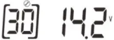
| 30 | PV Boost voltage setting | 14.2V (default) )
| Range of adjustment 13.8-14.5V |
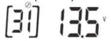
| 31 | PV Floating charging setting | 13.5V(default)
| Range of adjustment 13.5-13.7V |


| UP | Page up key |
| DOWN | Page down key |
| ENTE R | Confirm the exit key |
LCD display:
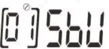
| The software material No. & version No.325-00 shall be displayed on LCD Screen when switch on.
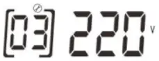
| The Battery voltage and rated power shall be displayed on the LCD screen when switch on. As this shown in Screen:3024 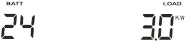 |
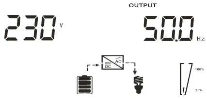
| Default Page: Output Voltage and Output Frequency.
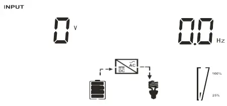
| Input Voltage and Input Frequency.
|
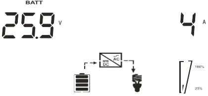
| Battery Voltage and Current.
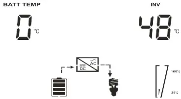
| BAT and Inverter Temperature
|

AGS function
AGS function information
The AGS function is that the inverter will start the generator automatically via the dry contact when the battery 1s low voltage.
Note:
The generator must have dry contact function.
If you connect AC grid and Generator to Inverter inputat the same time, the interlock device should beinstalled between generator output and inverter input. (To ensure the utility and generator will not provide power to inverter at the same time. It doesn’t need to be installed if only connect generator).
Dry contact operating voltage
| Set Low Shutdo wn Voltage | Operation Voltage | Restoring Voltage |
| 10V/ 20V/ 40V | DC< 10.5V/ 21V/ 42V | DC> 13.5V/ 27V/ 54V |
| 10.5V/ 21V/ 42V | DC< 11V/ 22V/ 44V | DC> 13.5V/ 27V/ 54V |
| 11V/ 22V/ 44V | DC< 11.5V/ 23V/ 46V | DC> 13.5V/ 2 7 V / 54V |
Thatis when the dry contact is engaged at DC<set low shutdown point+ 0.5V (battery low voltage warning point), at DC> 13.5V. (12V model)
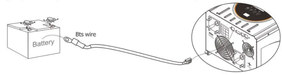
BTS function
BTS function description:
- The inverter collects the battery temperature through the BTS port, based on 25°Cwith each rise of 1°C, the charging voltage drops by 18mV/ at the set charging voltage (up t o 60°C) BTS down charge voltage is based on drops o f boost voltage and float voltage.
- Using an optional battery temperature cable to connect the inverter and battery.
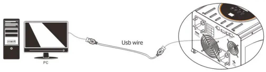
Communication
Computer Monitoring directions
- use the monitoring software: SolarPowerMonitor for communication. This software supports the communication function for various models of our company.
- The software will send the COM Port and inverter model automatically.
The operation steps are as follows
- Connectthelnverter to Computer with USBcable.
Install the software : Solar Power Monitor
Open the Powermonitor, turn on the machine
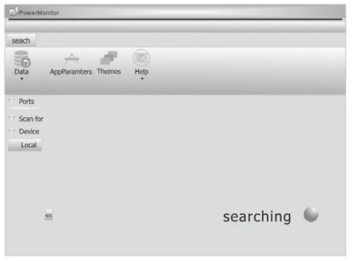
The SolarPowerMonitor will auto scan communication port
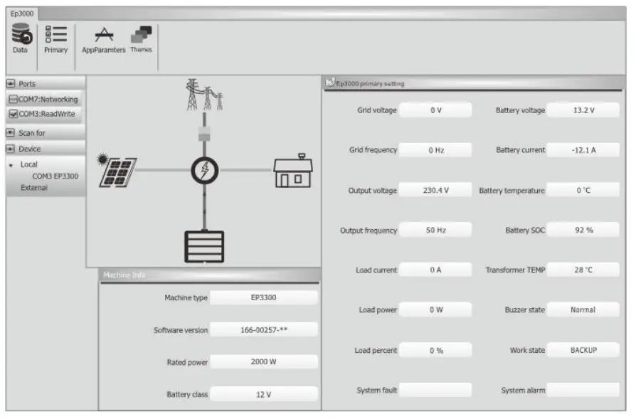
Wait for a moment, Power Monitor will work normally.
Monitor software function operation Specific function Operations of the monitoring software, please refering to the HELP docs after the connection is successful.
Specifications
Inverter Mode Specification
| Rated power(W) | 3KW |
| Power Factor | 1 |
| Wave form | Pure sine wave |
| Output voltage RMS | 110V/ 115V/120VAC(220V/230V/240VAC)1.10% |
| Output frequency | 50HZ or 60HZ ( f:0.3HZ) |
| Inverter efficiency(peak) | >80% |
| Overload | 1000/o<Load< 110% (alarm Smin then stop output and fault code 07) 110%<Load<125% (alarm 60s then stop output and fault code 07) Load>125% (alarm 10s then stop output and fault code 07) |
| Surge rating | 9000VA |
| Capable of starting electric motor | 1.5P |
| Battery voltage | 24VDC |
| Low battery cut off | (low voltage fault code04) 20/21/22V for 24V model |
| Low battery alarm | Add 0.5V/battery: (low battery alarm one second one time) (20/21/22V) +1Vdc for 24v model |
| High voltage alarm | Add + 1V/battery: (high voltage one second onetime/after 30s fault 03) (27.6-29V) + 2V for 24v model |
| Save mode | Load5_50±20W(120V)/100 i 20W(220V) |
| Operating Temperature Range | -0°c to 40°C |
| Storage Temperature | -15°C— 60°C |
| Audible Noise | 60db max |
AC Mode Specification
AC parameter
| Input waveform | Pure sine wave |
| Nominal input voltage | 120/230Vac (±3%) |
| Max input voltage | 140/270Vac MAX |
| Input frequency | 50HZ/60HZ (auto sensing) |
| Output waveform | Same as input waveform |
| Overload protection | Breaker + software protection |
| Output short circuit | Breaker+ software protection |
| Efficiency(AC mode) | >95%®load, full battery) |
| Transfer time AC TO DC | 15ms(max) |
| Transfer time DC TO AC | 15ms(max) |
AC input voltage range: (SV)
| model | range | Low cutoff | Low recover | High cutoff | High recover |
| 120V | narrow | AC<90V | AC>95V | AC>140V | AC<135V |
| F<40HZ | F>45HZ | F>70HZ | F<65HZ | ||
| wide | AC<70V | AC>75V | AC>140V | AC<I35V | |
| F<40HZ | F>45HZ | F>70HZ | F<65HZ | ||
| 220V | narrow | AC<180V | AC>190V | AC>270V | AC<265V |
| F<40HZ | F>45HZ | F>70HZ | F<65HZ | ||
| wide | AC<140V | AC>150V | AC>270V | AC<265V | |
| F<40HZ | F>45HZ | F>70HZ | F<65HZ |
Charge Mode Specifications Max charge current: (+5A)
| model | 3 K | 24V | 40A |
| Min charge current 10A. change by every 5A. | |||
Charge mode AC range:
| Setting | Low voltage | Charge mode | recover | Charge mode |
| 120V AC wide range | AC>135V | Stop charge | AC<130V | Charge recover |
| AC<75V | Stop charge | AC>80V | Charge recover | |
| 40< F<70HZ charge | ||||
| 220V AC wide range | AC>265V Stop charge AC<260V Charge recover | |||
| AC<155V Stop charge AC>160V Charge recover | ||||
| 40< F<70HZ charge | ||||
Solar charger(MPPT controller) electrical specification
| Type | MPPT-80A |
| Nominal system voltage | 12V / 24/ 48V(auto detection) ; |
| Maximum charge current | 80A i-4A |
| Battery voltage | 24V |
| Maximum solar input voltage | 145 i2V |
| PV array MPPT voltage range | 30-130V |
| Maximum input power | 2500W |
| Charging stages | Bulk,absorption, float |
| Over charging voltage | 30 .0V |
| Over charging comeback voltage | 29. 5V |
| Battery defect voltage | 17.0V |
| Charging curve | 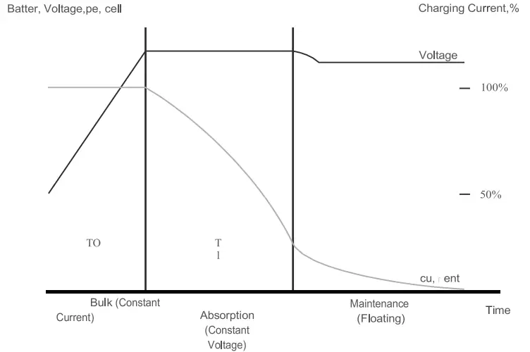 |
Charge mode:
| Charge current adjustable | Charge cureent adjustable : 10A-max (adjust by every 5A) |
| Battery voltage | 10-14.5Vdc/ 20-29Vdc/ 40-58Vdc |
| Short circuit protection | breaker |
| Over charge protection | Bat V charge voltage+1V/ batte ry,l s 1 time for 30s then alarm 03 |
| rule | Boost CC – Boost CV – Boost FV |
| Charge Stage Transition Definition | •Boost CC Stage: If A/C input is applied, the charger will run at full current in CC mode until the charger reaches the boost voltage. •Boost CV Stage: the charger will keep the boost voltage in Boost CV mode Until the charge current less 6A continue 1 minute or keep the boost voltage time more than 2hours . Then drop the voltage down to the float voltage. •Float Stage: In float mode, the voltage will stay at the float voltage. •If the A/C is reconnected , the charger will reset the cycle above. 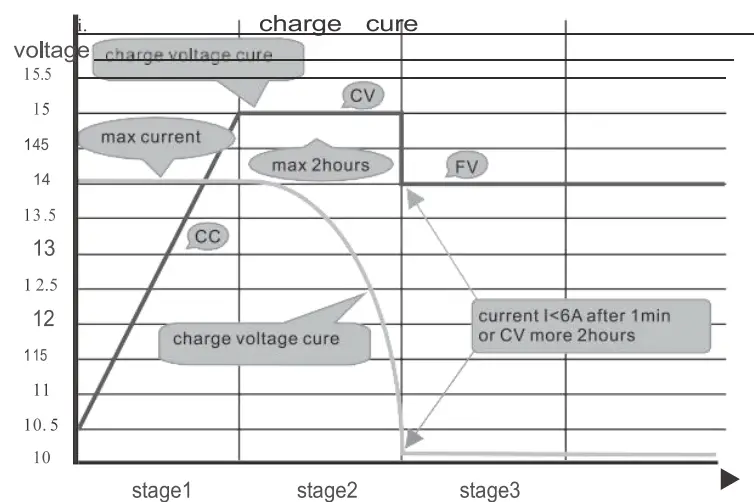 |
Fault Mode
LED instruction
| LED | LED state | information |
| LED AC(green) | Off | No AC input |
| On | AC normal | |
| Blink | AC over range | |
| LED Inv (yellow) | On | Inverter mode |
| LED Fault(red) | Off | normal |
| On | fault | |
| Blink | caution |
BUZZER instruction
| Buzzer state | information |
| Buzzer off | normal |
| Buzzer beep | caution |
| Buzzer on | fault |
LCD display instruction
When inverter alarm, even it back to recovery mode. We must restart inverter to clear fault.
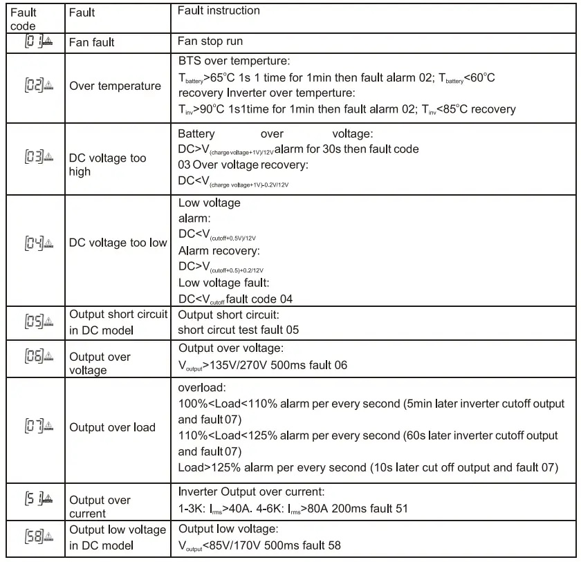
Trouble shooting
If machine enters into fault mode, please remove input power. Andaccording tothe table, deal with the following problems.
| LED/Buzzer | LCD | Explanation / Possible cause | What to do |
| Buzzer beeps continuously and red LED lson | Fault code 01 | Fan stop run | Check the fan. |
| Fault code 02 | Temperature of machine is too high. | Power off and waiting for minute | |
| Fault code 03 | Battery voltage is too high. | Check the battery specifications | |
| Fault code 04 | Battery voltage is too low. | Check the battery specifications | |
| Fault code 05 | Output short circuited | Remove your load and restart | |
| Fault code 06 | Inverter output voltage is high. | Return to repair center | |
| Fault code 07 | Over load | Decrease your load | |
| Fault code 51 | Output over current | Check if wiring is connected well and remove abnormal load. | |
| Fault code 58 | Output voltage is too low. | Decrease your load |
MPPT controller waming:
| Warn code | Warn information | Warn information specification | What to do |
| Hard ware protection | Return to repair center | ||
 | Over current | ||
| Current sensor error | |||
| MPPT controller over temperature | Stop PV charge soon | ||
| PV voltage too high | Check PV | ||
| PV voltage too low | |||
| Battery voltage too high | Check battery | ||
| Battery voltage too low | |||
| Current is unconrollable | Return to repair center | ||
| Parameter error | |||
| MPPT controller fan | Check MPPT fan |
Please down load the software “SolarPowerMonitor2.2.81”.
Download link:: https://Awww.s9.ro/spm8 https://cdn.mypni.com/public/Software/9502/solarpowermonitor2.2.81.zip


