LOREX E841CA SERIES 4K Ultra HD Bullet IP Camera

Package Contents
- 4K Ultra HD Bullet IP Camera
- Mounting Kit*
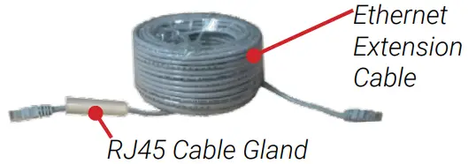
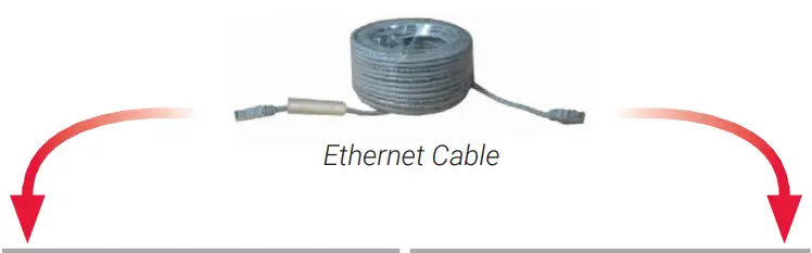
- Ethernet Extension Cable with Pre-attached RJ45 Cable Gland*
* Per camera in multi-camera packs.
ATTENTION
It is recommended to connect the camera to the NVR or an external PoE switch. If using a DC power adapter (not included) with the camera, a REGULATED power supply is REQUIRED for use with this camera. Use of a non-regulated, non-conforming power supply can damage this product and voids the warranty.
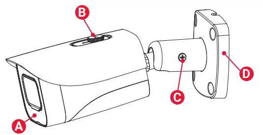
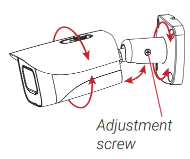
Camera Overview
A. Light Sensor and IR LEDs
B. Sun Shield Screw
C. Adjustment Screw
D. Camera Base
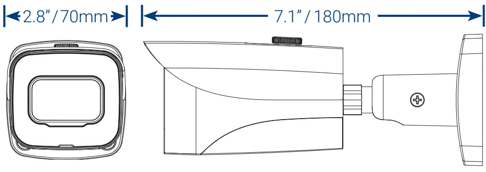
Dimensions
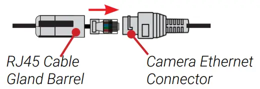
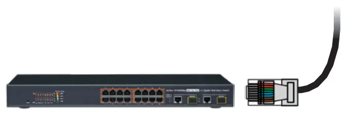
Using the RJ45 Cable Gland (Optional)
The RJ45 cable gland covers the camera’s Ethernet connector and the RJ45 plug to provide weather-resistance and protection from dust, dirt and other environmental contaminants.
The RJ45 cable gland is pre-attached to the included Ethernet extension cable.
To use the RJ45 cable gland:
Twist the RJ45 cable gland barrel securely onto the camera Ethernet connector.
NOTE: The RJ45 cable gland is weather-resistant. Seal the cap with silicone and/or electrical tape for additional sealing if it will be exposed to precipitation regularly.
Resources
Need Help?
Visit us online for up-to-date software and complete instruction manuals.
- Visit lorex.com
- Search for the model number of your product
- Click on your product 3 in the search results
- Click on the Downloads tab

Safety Precautions
- Use the camera only with compatible Lorex NVRs.
- Read this guide carefully and keep it for future reference.
- Follow all instructions for safe use of the product and handle with care.
- Use the camera within given temperature, humidity and voltage levels noted in the camera’s specifications.
- Do not disassemble the camera.
- Do not point the camera directly towards the sun or a source of intense light.
- Use only a regulated power supply with the product (optional). Use of a non-regulated, non-conforming power supply can damage the product and void the warranty.
- Periodic cleaning may be required. Use a damp cloth only. Do not use harsh cleaners or aerosol cleaners.
- The supplied cable is rated for surface mounting only. Cables for in-wall and floor-to-floor installations are sold separately (CMR type). These and other cables are available at lorex.com.
Disclaimers
- For a full list of compatible recorders, visit lorex.com/compatibility.
- Not intended for submersion in water. Installation in a sheltered location recommended.
- This camera includes an Auto Mechanical IR Cut Filter. When the camera changes between Day/Night viewing modes, an audible clicking noise may be heard from the camera. This clicking is normal, and indicates that the camera filter is working.
Installation Tips
- Point the camera where there is the least amount of obstructions (i.e., tree branches).
- Install the camera where vandals cannot easily reach.
- Secure cabling so that it is not exposed or easily cut.
- This camera is rated for outdoor use. Installation in a sheltered location is recommended.
Installing the Camera
ATTENTION
Test your camera prior to selecting a permanent mounting location by temporarily connecting the camera and cable to your NVR.
Before Installing the Camera
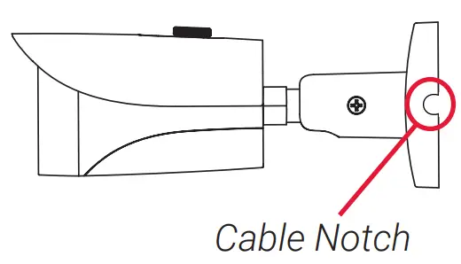
- Decide whether to run the cables through the wall / ceiling (drilling required) or along the wall / ceiling.
- If you run the cables along the wall / ceiling, you must run the cable through the cable notch on the base. This will keep the camera base flush to the surface when mounted.

To install your camera
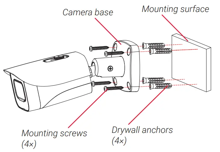
- Use the included mounting template to mark holes for the screws. Drill holes for the mounting screws.
NOTE: Insert the included drywall anchors if you are installing the camera in drywall. - Connect cables as shown in the section “Connecting the Camera”.
- Feed the cable through the mounting surface or cable notch and mount the camera stand to the surface using the provided screws.
- Use a Philips screwdriver (not included) to loosen the adjustment screw.
- Adjust the camera position as needed.
- Tighten the adjustment screw to secure the position.
- Remove the vinyl film from the camera lens when your installation is complete.

Connecting the Camera
 | |
Camera | NVR |
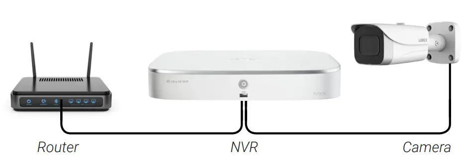
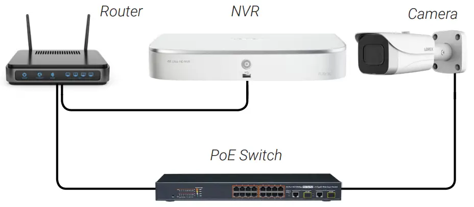
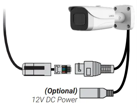 Connect the Ethernet cable to the camera. NOTE: A 12V DC power adapter (model #: ACCPWR12V1, not included) is only required if connecting the camera’s Ethernet cable to a router or switch that does not support PoE. | Connect the other end of the Ethernet cable to the NVR’s PoE ports. The camera may take a minute to power up after being connected. 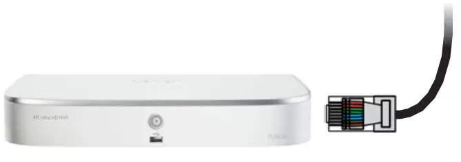 OR Connect the other end of the Ethernet cable to a router or switch on your network. See your NVR manual for details on connecting the camera to your NVR using a switch or router.
|
Setup Diagram
Scenario 1: Connect Cameras to NVR
Scenario 2: Connect Cameras to Local Area Network (LAN)
ATTENTION
- This camera is compatible only with select NVRs supporting 4K camera input. For a list of compatible recorders, visit lorex.com/compatibility.
- You must connect the camera to a supporting H.265 NVR to take advantage of H.265 compression. For instructions on enabling H.265 compression, visit lorex.com and search for “How do I enable H.265 compression?”.
Cable Extension Options
Extend the Ethernet cable run for your camera up to 300ft (91m). See table below. It is recommended to use UL CMR approved cables available at lorex.com.
| Cable Type | Max Cable Run Distance | Max # of Extensions |
| CAT5e (or higher) Ethernet cable | 300ft (91m) | 3 |
- You can use a RJ45 coupler or switch (not included) to connect male ends of Ethernet cable together.
- To extend the cable run beyond 300ft (91m), a switch will be required (sold separately).
Troubleshooting
| Problem | Solution |
| No picture / signal |
|
| Picture is too bright |
|
| Picture is too dark |
|
| Night vision is not working |
|
| Picture is not clear |
|
| Bright spot in video when viewing camera at night |
|
| Picture is in color in dark conditions |
|


 Ip Bullet Camera Owner's Manual")


