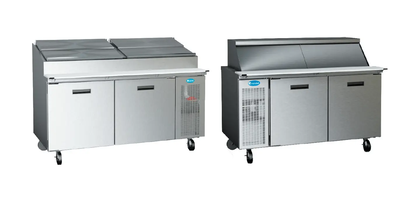
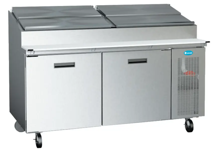
randell 9000W-290 Series Solid Hinged Door Prep Table
OPERATOR MANUAL
IMPORTANT INFORMATION, KEEP FOR OPERATOR
888-994-7636, fax 888-864-7636 unifiedbrands.net
THIS MANUAL MUST BE RETAINED FOR FUTURE REFERENCE. READ, UNDERSTAND AND FOLLOW THE INSTRUCTIONS AND WARNINGS CONTAINED IN THIS MANUAL.
FOR YOUR SAFETY Do not store or use gasoline or other flammable vapors and liquids in the vicinity of this or any other appliance.
WARNING R290 flammable refrigerant in use. Improper installation, adjustment, alteration, service or maintenance can cause property damage, injury or death. Read the installation, operating and maintenance instructions thoroughly before installing or servicing this equipment.
NOTIFY CARRIER OF DAMAGE AT ONCE It is the responsibility of the consignee to inspect the container upon receipt of same and to determine the possibility of any damage, including concealed damage. Unified Brands suggests that if you are suspicious of damage to make a notation on the delivery receipt. It will be the responsibility of the consignee to file a claim with the carrier. We recommend that you do so at once.
Manufacture Service/Questions 888-994-7636.
RETAIN THIS MANUAL FOR FUTURE REFERENCE
NOTICE: Due to a continuous program of product improvement, Unified Brands reserves the right to make changes in design and specifications without prior notice.
NOTICE: Please read the entire manual carefully before installation. If certain recommended procedures are not followed, warranty claims will be denied.
- MODEL NUMBER _________________________
- SERIAL NUMBER _________________________
- INSTALLATION DATE ______________________
The serial number is located behind the hinged vented door of the compressor machine compartment. An example is shown here.
EQUIPMENT DESCRIPTION
| MODEL | PAN CAPACITY 1/3 SIZE | L | D | H | DOORS | STORAGE CU. FT. | HP | VOLT | AMPS | NEMA | SHIP WT. | ||
| WORK SURFACE | REAR OF UNIT (CLOSED COVER) | OVERALL (COVER OPEN) | |||||||||||
| 8148N-290 | 6 | 48” | 33” | 35” | 44” | 52.5” | (1)27” | 9.0 | 1/3 | 115/60/1 | 6 | 5-15P | 405 |
| 8260N-290 | 8 | 60” | 33” | 35” | 44” | 52.5” | (2)24” | 14.67 | 1/3 | 115/60/1 | 6 | 5-15P | 459 |
| 8268N-290 | 9 | 68” | 33” | 35” | 44” | 52.5” | (2)27” | 17.76 | 1/3 | 115/60/1 | 6 | 5-15P | 484 |
| 8383N-290 | 11 | 83” | 33” | 35” | 44” | 52.5” | (2)24”,(1)21” | 23.55 | (2) 1/4 | 115/60/1 | 5.8 | 5-15P | 585 |
| 8395N-290 | 13 | 95” | 33” | 35” | 44” | 52.5” | (3)27” | 28.18 | (2) 1/4 | 115/60/1 | 5.8 | 5-15P | 630 |
| 84111N-290 | 15 | 111” | 33” | 35” | 44” | 52.5” | (3)24”,(1)21” | 32.81 | (2) 1/4 | 115/60/1 | 5.8 | 5-15P | 675 |
| MODEL | PAN CAPACITY 1/6 SIZE | L | D | H | DOORS | STORAGE CU. FT. | HP | VOLT | AMPS | NEMA | SHIP WT. | ||
| WORK SURFACE (NO CUTTING BOARD) | REAR OF UNIT (NO COVER) | OVERALL | |||||||||||
| 8148W-290 | 21 | 48” | 33” | 35” | 46.5” | 53.5” | (1)27” | 9.0 | 1/3 | 115/60/1 | 6 | 5-15P | 530 |
| 8268W-290 | 30 | 68” | 33” | 35” | 46.5” | 53.5” | (2)27” | 17.76 | 1/3 | 115/60/1 | 6 | 5-15P | 595 |
| 8395W-290 | 42 | 95” | 33” | 35” | 46.5” | 53.5” | (3)27” | 28.18 | (2) 1/4 | 115/60/1 | 5.8 | 5-15P | 785 |
| MODEL | PAN CAPACITY 1/6 SIZE | L | D | H | DOORS | STORAGE CU. FT. | HP (BASE & RAIL) | VOLT | AMPS | NEMA | SHIP WT. |
| 9148W-290 | 18 | 48″ | 33″ | 46.5″ | (1) 27″ | 5.5 | 1/3 | 115/60/1 | 6 | 5-15P | 405 |
| 9260W-290 | 24 | 60″ | 33″ | 46.5″ | (2) 24″ | 9.8 | 1/3 | 115/60/1 | 6 | 5-15P | 465 |
| 9272W-290 | 30 | 72″ | 33″ | 46.5″ | (2) 27″ | 11.2 | 1/3 | 115/60/1 | 6 | 5-15P | 510 |
Information contained in this document is known to be current and accurate at the time of printing/creation. Unified Brands recommends referencing our product line websites, unifiedbrands.net, for the most updated product information and specifications. © 2022 Unified Brands. All Rights Reserved.
IMPORTANT – READ FIRST – IMPORTANT
INTERIOR EVAPORATOR COVER
DANGER
RISK OF FIRE OR EXPLOSION. FLAMMABLE REFRIGERANT USED. DO NOT USE MECHANICAL DEVICES TO DEFROST REFRIGERATOR. DO NOT PUNCTURE REFRIGERANT TUBING.
RIESGO DE INCENDIO O EXPLOSIÓN. REFRIGERANTE INFLAMABLE UTILIZADO. NO UTILICE DISPOSITIVOS MECÁNICOS PARA DESCONGELAR EL REFRIGERADOR. NO PERFORE LA TUBERÍA DEL REFRIGERANTE.
EXTERIOR OF UNIT
RISK OF FIRE OR EXPLOSION. DISPOSE OF PROPERLY IN ACCORDANCE WITH FEDERAL OR LOCAL REGULATIONS.
FLAMMABLE REFRIGERANT USED.
A REGLAMENTOS FEDERALES O LOCALES. REFRIGERANTE INFLAMABLE UTILIZADO.
NEAR EXPOSED REFRIGERANT TUBING
CAUTION
RISK OF FIRE OR EXPLOSION DUE TO PUNCTURE OF REFRIGERANT TUBING; FOLLOW HANDLING INSTRUCTIONS CAREFULLY. FLAMMABLE REFRIGERANT USED.
NEAR MACHINE COMPARTMENT AND NAMEPLATE
RISK OF FIRE OR EXPLOSION. FLAMMABLE REFRIGERANT USED. TO BE REPAIRED ONLY BY TRAINED SERVICE PERSONNEL. DO NOT PUNCTURE REFRIGERANT TUBING.
CAUTION
RISK OF FIRE OR EXPLOSION. FLAMMABLE REFRIGERANT USED. CONSULT REPAIR MANUAL / OWNER’S GUIDE BEFORE ATTEMPTING TO INSTALL OR SERVICE THIS PRODUCT. ALL SAFETY PRECAUTIONS MUST BE FOLLOWED.
INSTALLATION
- CAUTION: THIS UNIT CONTAINS R290 FLAMMABLE REFRIGERANT. USE CAUTION WHEN HANDLING MOVING AND USE OF THE REFRIGERATOR OR FREEZER. AVOID DAMAGING THE REFRIGERANT TUBING OR INCREASE THE RISK OF A LEAK.
- WARNING: FAILURE TO FOLLOW INSTALLATION GUIDELINES AND RECOMMENDATIONS MAY VOID THE WARRANTY ON YOUR UNIT.
- WARNING: IT IS IMPORTANT THAT YOUR UNIT HAS ITS OWN DEDICATED LINE. CONDENSING UNITS ARE DESIGNED TO OPERATE WITH A VOLTAGE FLUCTUATION OF PLUS OR MINUS 10% OF THE VOLTAGE INDICATED ON THE UNIT DATA TAG. BURN OUT OF A CONDENSING UNIT DUE TO EXCEEDING VOLTAGE LIMITS WILL VOID THE WARRANTY.
THE DANFOSS CONTROLLER HAS LOW VOLTAGE PROTECTION AND WILL NOT OUTPUT VOLTAGE TO THE COMPRESSOR IF VOLTAGE IS LESS THAN 104V. - WARNING: IT IS IMPORTANT THAT A VOLTAGE READING BE MADE AT THE COMPRESSOR MOTOR ELECTRICAL CONNECTIONS, WHILE THE UNIT IS IN OPERATION TO VERIFY THE CORRECT VOLTAGE REQUIRED BY THE COMPRESSOR IS BEING SUPPLIED. LOW OR HIGH VOLTAGE CAN DETRIMENTALLY AFFECT OPERATION AND THEREBY VOID ITS WARRANTY.
- WARNING: EVAPORATOR FANS RUN CONTINUOUSLY WHILE THE BASE IS POWERED ON.
- WARNING: THIS UNIT IS INTENDED FOR USE IN LABORATORIES IN COMMERCIAL, INDUSTRIAL, OR INSTITUTIONAL OCCUPANCIES AS DEFINED IN THE SAFETY STANDARD FOR REFRIGERATION SYSTEMS, ASHRAE 15.
SELECTING A LOCATION FOR YOUR NEW UNIT
The following conditions should be considered when selecting a location for your unit:
- Floor Load: The area on which the unit will rest must be level, free of vibration, and suitably strong enough to support the combined weights of the unit plus the maximum product load weight. All casters must be in contact with the floor to support the weight. Casters may require shims in order for the caster to be in contact with the floor. NOTE: If there is a question pertaining to weight load limits, consult the factory at 1-888-994-7636.
- Ventilation: The air cooled self contained unit requires a sufficient amount of cool clean air. Avoid surrounding your unit around other heat generating equipment and out of direct sunlight. Also, avoid locating in an unheated room or where the room temperature may drop below 70° F (21°C) or above 86°F (32°C). Do not place any object that can block the ventilation exhaust from the machine compartment register.
- Clearance: This units clearance requirements are 0 in. at the top, 0 in. at the rear and 0 in. at each side.
INSTALLATION CHECKLIST
After the final location has been determined, refer to the following checklist prior to start-up:
- Check all exposed refrigeration lines to ensure that they are not kinked, dented, or rubbing together or rubbing against any steel.
- Check all visible components for any potential damage.
- Check that the condenser and evaporator fans rotate freely without striking any stationary members.
- Unit must be property leveled; Check all legs or casters ensure they all are in contact with the floor while maintaining a level work surface. Adjusting bullet feet height or shimming casters may be necessary if the floor is not level. NOTE: Damage to equipment may result if not followed. Unified Brands is not responsible for damage to equipment if improperly installed.
- Plug unit into power source. Unit will come on. If unit does not turn on, refer to controller operation section of this manual to manually turn on the unit.
- Allow unit time to cool down to holding temperature. If temperature adjustments are required, the control is located on the front panel. Confirm that the units is holding the desired temperature.
- If unit has drawers, check drawer to ensure the drawer slides freely and fully extents along with seating in the cabinet properly when closed.
- Refer to the front of this manual for serial number location. Please record this information in your manual on page 1 now. It will be necessary when ordering replacement parts or requesting warranty service.
- Allow your unit to operate for approximately 45 minutes before putting in food in the rail. Allow 2 hours for base of the unit to cool down to storage temperature, prior to loading product. NOTE: All motors are oiled and sealed.
ELECTRICAL SUPPLY
The wiring should be done by a qualified electrician in accordance with local electrical codes. A properly wired and grounded outlet will assure proper operation. Please consult the data tag attached to the compressor to ascertain the correct electrical requirements. Supply voltage and amperage requirements are located on the serial number tag located on the rear interior wall.
OPERATION
MORNING STARTUP
- Close the rail clean out valve located behind the louver and close the rail lid(s).
- Turn on the condiment rail by pressing and holding the rail control power button until the LED display turns on. Let the unit cool for a minimum of 45 minutes.
- Load pre-chilled product (37° or less) in standard pans and proceed with food preparation.
NORMAL OPERATION (Throughout day)
- Normal rail temperature reading will be less than 30° (rail control readout does not represent food or air temperatures).
- Lids should be kept closed during periods of inactivity to keep product temperatures as cool and fresh as possible.
- The frost above the product pans may come and go throughout the day -this is normal. The unit automatically regulates the rail temperature to keep your food safe and fresh.
- Although your marketable was designed for heavy use, excessive door openings should be avoided in order to maintain proper base temperature and reduce the possibility of coil freeze-up.
NIGHTLY ENERGY-SAVING SHUT DOWN
- Turn off the condiment rail by pressing and holding the rail control power button until the LED display turns off.
- Remove product from the rail at the end of the day’s preparation. The product may be stored in the refrigerated base compartment or another cooler.
- Remove any food spillage or debris from the rail, drain excess water and food through the clean out valve located behind the louvered panel. Before opening valve, position a suitable water tight container below valve to catch debris and liquid.
- Rail cleaning and sanitizing may be performed at this time (recommended).
- The base will continue to operate normally and may be used for overnight storage.
This equipment is intended for use in rooms having an ambient temperature of 30°C/86°F or less (NSF labeling requirement).
Use QR code to easily access more detailed operational information or instructions in Spanish or contact factory.
MECHANICAL COMPARTMENT
WARNING: BASE EVAPORATOR FANS ARE ALWAYS IN OPERATION WHEN THE UNIT IS ENERGIZED. DISCONNECT POWER TO THE UNIT PRIOR TO PERFORMING MAINTENANCE.
- To power on the base, press and hold the base control power button until the LED display turns on. To power on the rail, press and hold the rail control power button until the LED display turns on. The power controls are located above the louver panel.
- To power off the base press and hold the base control power button until the LED display turns off. To power off the rail press and hold the rail control power button until the LED display turns off. The power controls are located above the louver panel.
- The drain valve for the upper rail is found behind the hinged vented door. The rail may be drained by placing a pan under the drain valve and opening the valve. (See Evening Shut Down of Prep Rail).

MORNING STARTUP OF PREP RAIL
- Unit cleaning may be performed at this time.
- Turn on unit. See item 2 under the Mechanical Compartment section above for powering on the rail.
- Allow a minimum 45 minutes for your unit to cool down before loading product. A uniform frost pattern will appear on side walls and bottom of prep rail area.
- Load the product and proceed with food preparation. NOTE: Product entering unit must be at 35°F +/- 2°F.
EVENING SHUT DOWN OF PREP RAIL
- Remove product from unit at the end of the day’s preparation.
- Turn off unit. See item 3 under the Mechanical Compartment section above for powering on the rail.
- Unit cleaning may be performed at this time if the frost has melted off the surface.
- Once defrosted, the rail drain may be opened to remove any water that has resulted from the defrosting procedure.
WARNING: IT IS RECOMMENDED TO ONLY MAKE CHANGES OF 2 DEGREE INCREMENTS AT A TIME. ALLOW FOR THE UNIT TO OPERATE 24 HOURS BETWEEN ADJUSTMENTS. IF THE 2 DEGREE ADJUSTMENT IS NOT ENOUGH ANOTHER ADJUSTMENT CAN BE MADE. IF THE SETTINGS NEED TO GO ABOVE OR BELOW THIS POINT THERE MAY BE OTHER CONTRIBUTING FACTORS AS TO THE CAUSE OF THE TEMPERATURE VARIANCES, PLEASE CONTACT THE FACTORY AT 1-800-621-8560.
AMBIENT CONDITIONS
Unit is designed for normal operating temperatures between 70° F (21°C) – 86°F (32°C). Operating outside of those temperatures may cause premature product wear or failure.
Unified Brands has attempted to preset the temperature control to ensure that your unit runs at an optimum temperature, but due to varying ambient conditions, including elevation, food type and your type of operation, you may need to alter this temperature using control adjustment until desired temperature is reached.
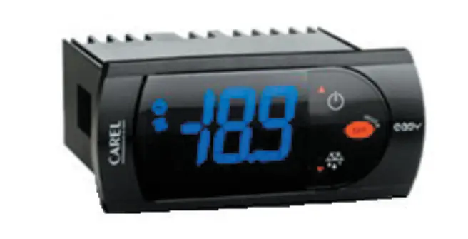
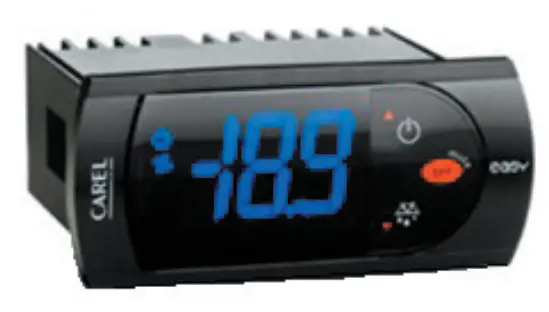
CAREL CONTROLLER OPERATION
| LED | FUNCTION |
 | Compressor energized |
 | Defrost in progress |
 | Evaporator fan energized |
 | An alarm is occurring |
- POWER ON / OFF: Press and hold the Power Button
 seconds for more than 3 or until LED display turns On/Off.
 - MANUAL DEFROST: Press and hold the Defrost Button
 for more than 3 seconds (melting snowflake will light).
 - CHANGE SET POINT: To raise temperature
- Press and hold set button for 1 second to access set point.
- When set point starts flashing, press up button to adjust set point.
- Press set button for 3-seconds to save set point.
CHANGE SET POINT: To lower temperature
- Press and hold set button for 1 second to access set point.
- When set point starts flashing, press down button to adjust set point.
- Press set button for 3-seconds to save set point.
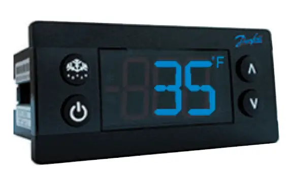
DANFOSS CONTROLLER OPERATION
| LED | FUNCTION |
 | Compressor energized & Evaporator fan de-energized |
 | Defrost in progress |
 | Fans delay after defrost completion |
 | Evaporator fan energize |
| An alarm is occurring | |
| Temperature unit |
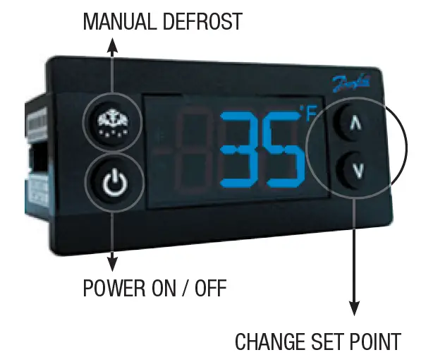
- POWER ON / OFF: Press and hold the power button until LED display turns On / Off
- MANUAL DEFROST: Press and hold “Defrost” Button
- CHANGE SET POINT: To raise temperature
- Press and hold “ ” to access set point.
- When set point start flashing, Press “ ” to adjust set point.
- After 30 seconds, the display automatically reverts to showing the current temperature.
CHANGE SET POINT: To lower temperature
- Press and hold “v” to access set point.
- When set point start flashing, Press “v” to adjust set point.
- After 30 seconds, the display automatically reverts to showing the current temperature.
CHANGE FROM ºF /ºC :
- Press the up/down buttons simultaneously for 5 seconds to access the menu.
- Password is requested. Password is 000.
- Press the bottom left button to OK the password.
- Using the up/down buttons, navigate to the “diS” level. Press the bottom left button to OK the selection.
- Using the up/down buttons, navigate to the “CFu” level. Press the bottom left button to OK the selection.
- “-F” designates Fahrenheit.
- “-C” designates Celsius.
- Press the top left button repeatedly to return to exit and return to the home screen.
DRAINING THE RAIL
- Open mechanical compartment door
- Place container under drain valve
- Open valve until all water has drained
- Close valve
- Discard water
DRAWER REMOVAL
- Fully extend the drawer that is to be removed.
- Remove product pans from drawer.
- Lift up the drawer stop tabs on each side of drawer track.
- Pull drawer out while lifting the tabs.
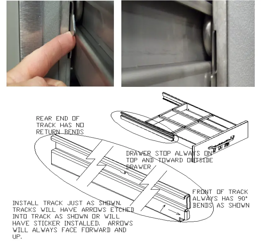
DRAWER INSTALLATION
To remove and re-install individual drawers and drawer tracks, please refer to the figure above for proper installation instructions.
MAINTENANCE
- WARNING: DO NOT USE SHARP UTENSILS AND/OR OBJECTS.
- WARNING: DO NOT USE STEEL PADS, WIRE BRUSHES, SCRAPERS, OR CHLORIDE CLEANERS TO CLEAN YOUR STAINLESS STEEL.
- CAUTION: DO NOT USE ABRASIVE CLEANING SOLVENTS, AND NEVER USE HYDROCHLORIC ACID (MURIATIC ACID) ON STAINLESS STEEL.
- WARNING: DO NOT PRESSURE WASH EQUIPMENT AS DAMAGE TO ELECTRICAL COMPONENTS MAY RESULT.
Unified Brands strongly suggests a preventive maintenance program which would include the following monthly, weekly, and daily procedures:
If a failure of the equipment is a direct result of any of the Preventative Maintenance guidelines being neglected, the repairs and parts replacements will not be covered under warranty.
It is recommended that the customer contact the local Authorized Service Agent to provide a quote to perform periodic Preventative Maintenance.
WEEKLY PM PROCEDURES
- Clean all gaskets on a weekly if not daily basis with a solution of warm water and a mild detergent to extend gasket life. Do not use bleach for cleaning gaskets. Bleach will cause the gaskets to become brittle and not reach their normal life expectancy.
- Clean and disinfect rail drains with a solution of warm water and mild detergent on a weekly basis. It is recommended to open and close the drain valve as the hot water is flowing through to clean any debris from the internal valve components.
MONTHLY PM PROCEDURES
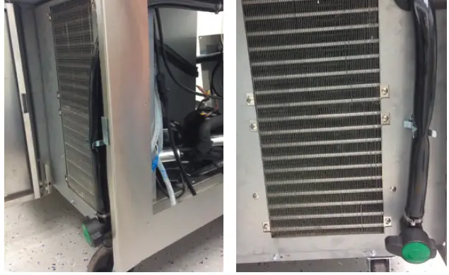
- Cleaning of all condenser coils on a monthly basis. Condenser coils are a critical component in the life of the compressor and must remain clean to assure proper air flow and heat transfer. Failure to maintain this heat transfer will affect unit performance and eventually destroy the compressor. Clean the condenser coils with coil cleaner and/or a vacuum, cleaner and brush. NOTE: Brush coil in direction of fins, normally vertically as to not damage or restrict air from passing through condenser.
- Clean and disinfect drain lines and evaporator pan with a solution of warm water and mild detergent on a monthly basis. Remove clear plastic drain line from plastic tray of condensing unit and place pan under end of drain tube. Discard waste water from pan when cleaning is complete. Re-insert plastic drain tube into position on condensing unit.
- Remove drawer tracks as per instructions on Drawer Installation guidelines. Once drawers are removed wipe away any debris buildup from the drawer tracks.
The roller bearings come lubricated from the factory. Excessive oils and or water may remove the oils. It may be required to add lithium grease from time to time on bearings that appear dry. - Inspect all silicone seams at interior of the rail and refrigerated base cabinet on a monthly basis. Re-apply food grade silicone sealant as needed to any seams where silicone has peeled away or cracked. Apply silicone to a clean dry surface. Allow sufficient drying time to assure best adhesion of sealant.
RECOMMENDED CLEANERS FOR YOUR STAINLESS STEEL INCLUDE THE FOLLOWING:
| JOB | CLEANING AGENT | COMMENTS |
| Routine cleaning | Soap, ammonia, detergent Medallion | Apply with a sponge or cloth |
| Fingerprints and smears | Arcal 20, Lac-O-Nu, Ecoshine | Provides a barrier film |
| Stubborn stains and discoloration | Cameo, Talc, Zud, First Impression | Rub in the direction of the polish lines |
| Greasy and fatty acids, blood, burnt-on foods | Easy-Off, Degrease It, Oven Aid | Excellent removal on all finishes |
| Grease and Oil | Any good commercial detergent | Apply with a sponge or cloth |
| Restoration/Preservation | Benefit, Super Sheen | Good idea monthly |
Reference: Nickel Development Institute, Diversey Lever, Savin, Ecolab, NAFEM
Proper maintenance of equipment is the ultimate necessity in preventing costly repairs. By evaluating each unit on a regular schedule, you can often catch and repair minor problems before they completely disable the unit and become burdensome on your entire operation.
For more information on preventive maintenance, consult your local service company or CFESA member. Most repair companies offer this service at very reasonable rates to allow you the time you need to run your business along with the peace of mind that all your equipment will last throughout its expected life. These services often offer guarantees as well as the flexibility in scheduling or maintenance for your convenience. For a complete listing of current Unified Brands ASA please visit www.unifiedbrands.net.
Unified Brands believes strongly in the products it manufactures and backs those products with one of the best warranties in the industry. We believe with the proper maintenance and use, you will realize a profitable return on your investment and years of satisfied service.
REPLACEMENT PARTS
To order parts, contact your Authorized Service Agent. Supply the model designation, serial number, part description, part number, quantity, and when applicable, voltage and phase.
CONTACT US
If you have questions pertaining to the content in this manual, contact Unified Brands at 888-994-7636.
TROUBLESHOOTING
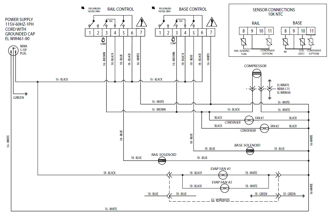
This unit is designed to operate smoothly and efficiently if properly maintained. However, the following is a list of checks to make in the event of a problem. Wir-ing diagrams are found at the end of this manual. When in doubt, turn unit off and contact service at 888-994-7636 or [email protected].
| SYMPTOM | POSSIBLE CAUSE | PROCEDURE |
|
Unit does not run | No power to unit | Plug in unit |
| Control in OFF position | Turn controller on | |
| Faulty control | Call for service at 888-994- 7636 | |
| Unit too cold | Incorrect set point | Adjust control set point |
|
Unit too warm | Door / drawer ajar | Ensure door / drawer is fully closed |
| Gasket torn or out of place | Inspect the gasket for wear and position | |
| Incorrect set point | Adjust control set point | |
| Warm product introduced to cabinet | Pre-chill product 37ºF | |
| Ice on the coil | Initiate manual defrost | |
| Unit noisy | Ice on the coil | Initiate manual defrost |
| Unit does not defrost | Excessive ice on the coil | Initiate manual defrost |
CAREL CONTROLLER CODES
| DISPLAYED ALARM CODE | ALARM |
| E0 | Control probe |
| E1 | Defrost probe |
| dOr | Open door |
| LO | Low temperature |
| HI | High temperature |
| CHt | Dirty condenser |
DANFOSS CONTROLLER CODES
LEA Continuous Compressor Runtime Inspect door/drawer sealingE01S1 Sensor Failure Contact serviceE02S2 Sensor Failure Contact serviceE03S3 Sensor Failure Contact serviceE04S4 Sensor Failure Contact service
| DISPLAYED ALARM CODE | ALARM | ACTION |
| Hi | High Temperature Alarm | Inspect door/drawer sealing |
| Contact service | ||
| Lo | Low Temperature Alarm | Contact service |
|
CON | Condenser Temperature High Limit | Clean condenser coil |
| Inspect coil for any objects obstruction hindering airflow | ||
| Contact service | ||
| uHi | Line Voltage Too High | Verify voltage of power source, to be performed by qualified technician |
| Contact service | ||
| uLi | Line Voltage Too Low | Verify voltage of power source, to be performed by qualified technician |
| Contact service | ||
| Inspect condenser coil, clean if necessary | ||
| Contact service |
SERVICE
- CAUTION: COMPONENT PARTS SHALL BE REPLACED WITH FACTORY OEM PARTS. SERVICE WORK SHALL BE DONE BY FACTORY AUTHORIZED SERVICE PERSONNEL, SO AS TO MINIMIZE THE RISK OF POSSIBLE IGNITION DUE TO INCORRECT PARTS OR IMPROPER SERVICE.
- CAUTION: BEFORE MAKING ANY REPAIRS, ENSURE THE UNIT IS DISCONNECTED FROM ITS POWER SOURCE.
This piece of equipment uses a R290 Refrigeration system. This equipment has been clearly marked on the serial tag the type of refrigerant that is being used. There is also a warning labels stating that the unit contains R290 refrigerant. R290 is safe to use as long as you follow these warning labels.
No smoking or open flames when servicing this equipment. If needed, use a CO2 or dry-powder type fire extinguisher
Replacement parts used on any R290 Refrigeration system cabinet must have specific UL certification for non-sparking components.
Only authorized service technician, certified in R290 system should service this equipment.
MANIFOLD SET
A R134A manifold set can be used for servicing this equipment.
REFRIGERANT RECOVERY
Follow all national and local regulations for R-290 refrigerant recovery.
LEAKING CHECKING AND REPAIR
Leak check an R-290 system the same way you would an R-134a or R-404A system with the following exceptions.
- Do not use a Halid leak detector on a R290 system.
- Electronic leak detector must be designated specifically for combustible gas. Use of a bubble solution or an ultrasonic leak detector are acceptable.
When repairing a leak, it is recommended using oxygen free dry nitrogen with a trace gas not exceeding 200PSI.
When accessing an R290 system, piercing valves are not to remain on the equipment in a permanent manner. After charge is recovered, Schrader valves are to be installed on the process stubs. Proper charge is to be weighed into the system and the system is to be leak checked afterwards.
The R290 equipment must have red process tubes and other devices through which the refrigerant is serviced, such as any service port. This color marking must remain on the equipment. If marking is removed, it must be replace and extend at least 2.5 centimeters (1”) from the compressor.
CHARGING
Follow the charge amount specified on the data tag. It is recommended to use the shortest hoses possible to prevent undercharging.
- Ensure the system is sealed and leak checked
- Evacuate system to a minimum 500 micron
- Weigh in correct charge
- Leak check the system again
- Bleed the refrigerant from the high side hose to the low side hose
- Disconnect the hoses
- Remove line taps
WARRANTY
Congratulations on the purchase of your new Unified Brands equipment. We hope you enjoy many years of reliable service in connection with the same. Please review all of the important safety and operational information contained in the Operator’s Manual for this equipment before it is placed in service. If you have any questions related to equipment set up, operations, or service, please call 888-994-7636.
In addition, please review the sales terms and conditions set forth below.
*****IMPORTANT NOTICE*****
WARRANTIES, LIMITATIONS ON WARRANTIES, AND LIMITATION OF REMEDIES
The following Warranties, Limitation on Warranties, and Limitation of Remedies are included in the terms of sale for this product. Please read this entire warranty and all warranty modifications, disclaimers, and limitations of remedies set forth herein before accepting or using this equipment or product. Customer acknowledges and accepts the provisions of this notice by Customer’s acceptance and use of the product. If these provisions are not acceptable and agreed to by Customer, then please return this product in its unused condition to Unified Brands or a Unified Brands authorized dealer.
UNIFIED BRANDS warrants this product against defects in material and workmanship under normal use and services for which this product was designed. This warranty runs only to the original end user and is in lieu of any other liability for defects. THE WARRANTIES EXPRESSED IN THESE TERMS AND CONDITIONS ARE IN PLACE OF ANY AND ALL OTHER EXPRESS WARRANTIES (UNLESS SEPARATELY STATED IN PRINTED MATERIAL PREPARED BY US DESCRIBING OUR EQUIPMENT) AND EXCLUDE ALL IMPLIED WARRANTIES, INCLUDING, BUT NOT LIMITED TO, ANY WARRANTY OF MERCHANTABILITY OR FITNESS FOR ANY PARTICULAR PURPOSE; NOR ARE THERE ANY OTHER WARRANTIES, EXPRESS OR IMPLIED, BY OPERATION OF LAW OR OTHERWISE. In no event shall UNIFIED BRANDS be liable for damages or delay or for any consequential, special or contingent damages arising out of any breach of our warranty, whether or not we have knowledge of specific needs or our employees or agents have given any specific assurances. Anyone claiming that there has been a breach of warranty by UNIFIED BRANDS must give us written notice within THIRTY (30) days after discovery of the relevant defect or the right to assert such claim will have been waived conclusively and provided further that any such claim must also be asserted within the general warranty period for such equipment and/or parts.
UNIFIED BRANDS will not be liable for any expense incurred without our prior written authorization for alterations made outside of our factory or for repairs which are not performed by UNIFIED BRANDS authorized service departments using UNIFIED BRANDS factory parts. Nor shall we be responsible for the performance of equipment as to which any repairs, revisions or alterations have been made by others.
THE EXCLUSIVE REMEDY OF THE USER OR BUYER AND THE EXCLUSIVE LIABILITY OF UNIFIED BRANDS OR ANY SELLER OF UNIFIED BRANDS PRODUCTS, FOR ANY AND ALL CLAIMS, LOSSES, INJURIES, OR DAMAGES (INCLUDING CLAIMS BASED ON BREACH OF WARRANTY, CONTRACT, NEGLIGENCE, TORT, STRICT LIABILITY, OR OTHERWISE) RESULTING FROM OR ARISING OUT OF THE USE OF HANDLING OF THIS PRODUCT, SHALL BE THE RETURN OF THE PURCHASE PRICE OR AN AMOUNT NOT TO EXCEED THE ORIGINAL PURCHASE PRICE OF THE PRODUCT OR, AT THE ELECTION OF UNIFIED BRANDS OR THE SELLER, THE REPLACEMENT OF THE PRODUCT.

https://unifiedbrands.net/Randell-Warranty-Information
Parts List
| 8148N-290 | 8260N-290 | 8268N-290 | 8383N-290 | 8395N-290 | 84111N-290 | 8148W-290 | 8268W-290 | 8395W-290 | 9148W-290 | 9260W-290 | 9272W-290 | ||
| SERVICE PART | CAREL CONTROLLER DESCRIPTION | ||||||||||||
| RP CNT1720BCAR | CONTROLLER, CAREL, PROGRAMMED – BASE – SGL COMPR SYSTEM | X | X | X | X | X | X | X | X | ||||
| RP CNT1720RCAR | CONTROLLER, CAREL, PROGRAMMED – RAIL – SGL COMPR SYSTEM | X | X | X | X | X | X | X | X | ||||
| RP CNT1805BCAR | CONTROLLER, CAREL, PROGRAMMED – BASE – DBL COMPR SYSTEM | X | X | X | X | ||||||||
| RP CNT1805RCAR | CONTROLLER, CAREL, PROGRAMMED – RAIL – DBL COMPR SYSTEM | X | X | X | X | ||||||||
| RF CNT2103 | THERMISTOR, CAREL, QTI, AIR SENSOR, BARE LEADS, BLACK, 10′ | X | X | X | X | X | X | X | X | X | X | X | X |
| RF CNT2104 | THERMISTOR, CAREL, QTI, COIL SENSOR, BARE LEADS, BLUE, 10′ | X | X | X | X | X | X | X | X | X | X | X | X |
| PP STK1802 | OVERLAY, CONTROL PANEL, 8000N COMMON | X | X | X | X | X | X | X | X | X | X | X | X |
* = NOT SHOWN
| 8148N-290 | 8260N-290 | 8268N-290 | 8383N-290 | 8395N-290 | 84111N-290 | 8148W-290 | 8268W-290 | 8395W-290 | 9148W-290 | 9260W-290 | 9272W-290 | ||
| SERVICE PART | DANFOSS CONTROLLER DESCRIPTION | ||||||||||||
| RP CNT1720BC | CONTROLLER, DANFOSS, PROGRAMMED – BASE – SGL COMPR SYSTEM | X | X | X | – | – | – | X | X | – | X | X | X |
| RP CNT1720RC | CONTROLLER, DANFOSS, PROGRAMMED – RAIL – SGL COMPR SYSTEM | X | X | X | – | – | – | X | X | – | X | X | X |
| RP CNT1805B | CONTROLLER, DANFOSS, PROGRAMMED – BASE – DBL COMPR SYSTEM | – | – | – | X | X | X | – | – | X | – | – | – |
| RP CNT1805R | CONTROLLER, DANFOSS, PROGRAMMED – RAIL – DBL COMPR SYSTEM | – | – | – | X | X | X | – | – | X | – | – | – |
| RF CNT1602 | THERMISTOR, DANFOSS, QTI, COIL SENSOR, MOLDED END, BLUE, 10′ | X | X | X | X | X | X | X | X | X | X | X | X |
| RF CNT1603 | THERMISTOR, DANFOSS, QTI, AIR SENSOR, MODLED END, BLACK, 10′ | X | X | X | X | X | X | X | X | X | X | X | X |
| PP STK1802 | OVERLAY, CONTROL PANEL, 8000N COMMON | X | X | X | X | X | X | X | X | X | X | X | X |
* = NOT SHOWN
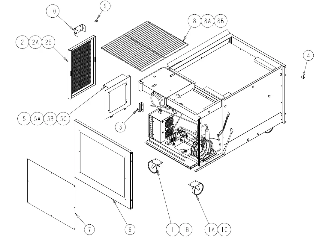
| 8148N-290 | 8260N-290 | 8268N-290 | 8383N-290 | 8395N-290 | 84111N-290 | 8148W-290 | 8268W-290 | 8395W-290 | |||
| ITEM | SERVICE PART | DESCRIPTION | |||||||||
| 1 | HD CST060 | 6″ CASTERS W/ BRAKE | X | X | X | X | X | X | X | X | X |
| 1A | HD CST061 | 6″ CASTERS W/O BRAKE | X | X | X | X | X | X | X | X | X |
| 1B | HD CST040HD | 4″ CASTERS W/ BRAKE | X | X | X | X | X | X | X | X | X |
| 1C | HD CST041HD | 4″ CASTERS W/O BRAKE | X | X | X | X | X | X | X | X | X |
| 2 | RP LVR1803 | LOUVER, HINGED | X | – | X | X | X | X | X | X | |
| 2A | RP LVR1804 | LOUVER, HINGED | – | X | – | – | – | – | – | – | – |
| 2B | RP LVR1805 | LOUVER, HINGED | – | – | – | – | – | X | – | – | – |
| 3 | HD CTH9901 | LOUVER MAGNET | X | X | X | X | X | X | X | X | X |
| 4 | HD BMP034 | BUMPER, RUBBER | X | X | X | X | X | X | X | X | X |
| 5 | RP SHD1805 | SHROUD, COND UNIT | X | – | X | – | X | – | X | X | – |
| 5A | RP SHD1806 | SHROUD, COND UNIT | – | X | – | – | – | – | – | – | – |
| 5B | RP SHD1807 | SHROUD, COND UNIT | – | – | – | X | X | – | – | – | X |
| 5C | RP SHD1808 | SHROUD, COND UNIT | – | – | – | – | – | X | – | – | – |
| 6 | RP PNL1803 | COVER, ACCCESS SIDE CMPR, L OR R | – | – | – | X | X | X | – | – | X |
| 7 | HD SHL180 | SHELF 22″ X 25″ | X | – | X | – | X | – | X | – | X |
| 7A | HD SHL160 | SHELF 19″ X 25″ | – | X | – | X | – | X | – | – | – |
| 7B | HD SHL9912 | SHELF 16.15″ X 25″ | – | – | – | X | – | X | – | – | – |
| 8 | HD PIN0102 | SHELF SUPPORT PIN | X | X | X | X | X | X | X | X | X |
| 9 | RP BRK0107 | SHELF SUPPORT – FRT & BACK | – | – | – | X | X | X | – | – | X |
| 10 | RP BRK0108 | SHELF SUPPORT BETWEEN DOORS | X | X | X | X | X | X | X | X | X |
| 11 | RP BRK1811 | LOUVER MOUNTING HINGE BRACKET | X | X | X | X | X | X | X | X | X |
| 12* | EL WIR1703 | POWER CORD 16/3 – 9′ – 90 | X | X | X | X | X | X | X | X | X |
| 13* | HD LEG9902 | 6″ LEG W/ BULLET FOOT | X | X | X | X | X | X | X | X | X |
| 14* | RP BCK0107 | S/S BACK PANEL 48″ | X | – | – | – | – | – | X | – | – |
| 14A* | RP BCK0108 | S/S BACK PANEL 60″ | – | X | – | – | – | – | – | – | – |
| 14B* | RP BCK0109 | S/S BACK PANEL 68″ | – | – | X | – | – | – | – | X | – |
| 14C* | RP BCK0110 | S/S BACK PANEL 83″ | – | – | – | X | – | – | – | – | – |
| 14D* | RP BCK0111 | S/S BACK PANEL 95″ | – | – | – | – | X | – | – | – | X |
| 14E* | RP BCK0112 | S/S BACK PANEL 111″ | – | – | – | – | – | X | – | – | – |
| 15 | RP END1901 | SIDE PANEL | X | X | X | X | X | X | X | X | X |
* = NOT SHOWN
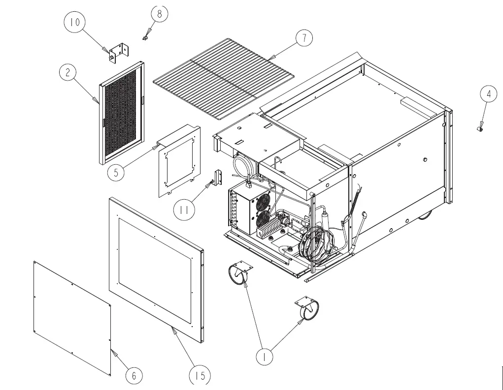
| 9148W-290 | 9260W-290 | 9272W-290 | |||
| ITEM | SERVICE PART | DESCRIPTION | |||
| 1 | HD CST060 | 6″ CASTERS W/ BRAKE | X | X | X |
| 1A | HD CST061 | 6″ CASTERS W/O BRAKE | X | X | X |
| 1B | HD CST040HD | 4″ CASTERS W/ BRAKE | X | X | X |
| 1C | HD CST041HD | 4″ CASTERS W/O BRAKE | X | X | X |
| 2 | RP LVR1807 | LOUVER, HINGED | X | – | – |
| 2A | RP LVR1808 | LOUVER, HINGED | – | X | – |
| 2B | RP LVR1809 | LOUVER, HINGED | – | – | X |
| 3 | HD CTH9901 | LOUVER MAGNET | X | X | X |
| 4 | HD BMP034 | BUMPER, RUBBER | X | X | X |
| 5 | RP SHD1814 | SHROUD, COND UNIT | X | – | – |
| 5A | RP SHD1815 | SHROUD, COND UNIT | – | X | – |
| 5B | RP SHD1816 | SHROUD, COND UNIT | – | – | X |
| 6 | HD SHL160 | SHELF 19″ X 25″ | X | – | X |
| 6A | HD SHL180 | SHELF 22″ X 25″ | – | X | – |
| 7 | HD PIN001 | SHELF SUPPORT PIN | X | X | X |
| 8* | RP SPT007 | SHELF SUPPORT | X | X | X |
| 9 | RP BRK1811 | LOUVER MOUNTING HINGE BRACKET | X | X | X |
| 10* | RP BRK0108 | SHELF SUPPORT BETWEEN DOORS | – | X | X |
| 11* | HD LEG9902 | 6″ LEG W/ BULLET FOOT | X | X | X |
| 12* | RP BCK0301 | S/S BACK PANEL 48″ | X | – | – |
| 12A* | RP BCK0304 | S/S BACK PANEL 60″ | – | X | – |
| 12B* | RP BCK0113 | S/S BACK PANEL 72″ | – | – | X |
| 13* | EL WIR469A | CORD, 14 GA 18” FEMALE 000469-14 | X | X | X |
| 14* | EL WIR1703 | POWER CORD, 9’ 16/3 W/90*-45* ANGLE PLUG (SJTO WIRE) | X | X | X |
* = NOT SHOWN
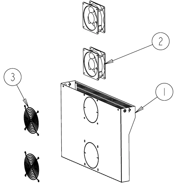
| 8148N-290 | 8260N-290 | 8268N-290 | 8383N-290 | 8395N-290 | 84111N-290 | 8148W-290 | 8268W-290 | 8395W-290 | |||
| ITEM | SERVICE PART | DESCRIPTION | |||||||||
| 1 | RP FAN1801 | FAN ASSIST ASSY | – | – | – | – | X | X | – | – | X |
| 2 | RF FAN1401 | FAN ASSIST MOTOR | – | – | – | – | X | X | – | – | X |
| 3 | RF FAN0703 | FAN ASSIST FAN GUARD | – | – | – | – | X | X | – | – | X |
* = NOT SHOWN
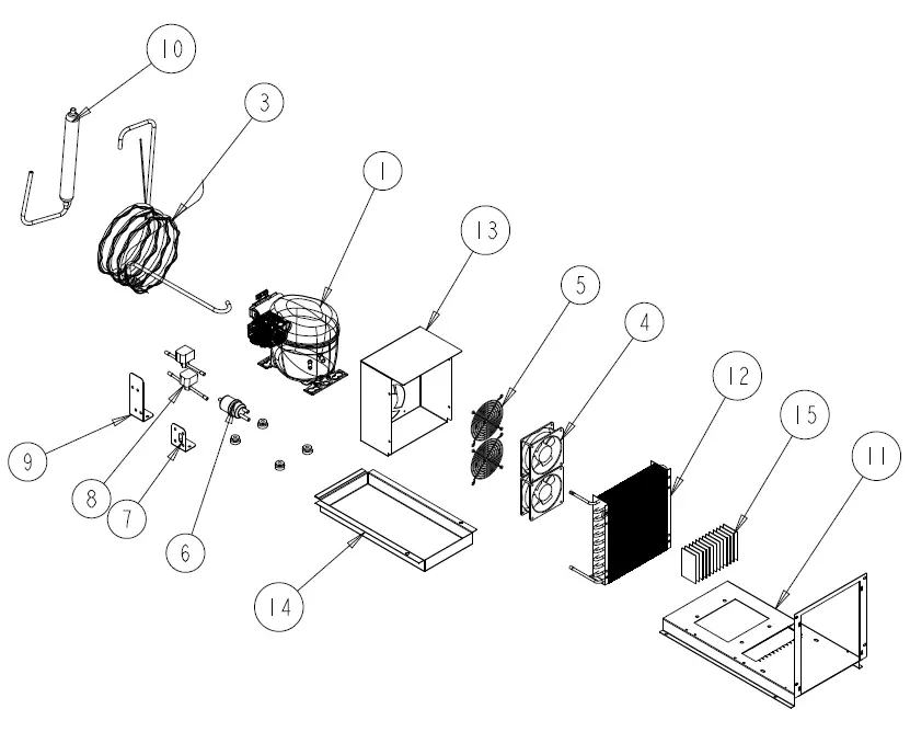
| 8148N-290 | 8260N-290 | 8268N-290 | 8383N-290 | 8395N-290 | 84111N-290 | 8148W-290 | 8268W-290 | 8395W-290 | 9148W-290 | 9260W-290 | 9272W-290 | |||
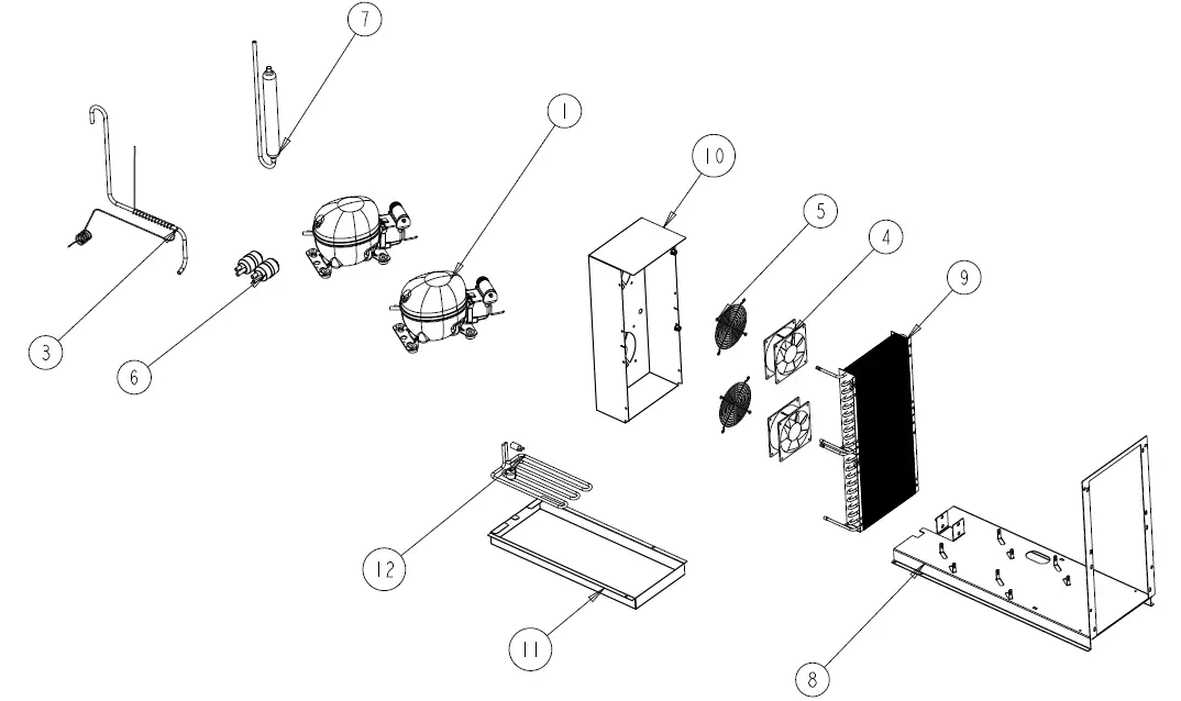
| ITEM | SERVICE PART | DESCRIPTION | ||||||||||||
| 1 | RF CMP1702 | COMPRESSOR, 1/3HP, R290, EMBRACO FFU130UAX | X | X | X | – | – | – | X | X | – | X | X | X |
| 2* | RF CMP1702SC | COMPRESSOR, START COMPONENTS | X | X | X | – | – | – | X | X | – | X | X | X |
| 3 | RP CAP1801 | CAP, TUBE – RAIL | X | X | X | – | – | – | X | X | – | X | X | X |
| 4 | RF FAN1401 | CONDENSER FAN | X | X | X | – | – | – | X | X | – | X | X | X |
| 5 | RF FAN0703 | FAN GUARD | X | X | X | – | – | – | X | X | – | X | X | X |
| 6 | RF FLT251 | FILTER DRIER, 1/4″ DBL INLET | X | X | X | – | – | – | X | X | – | X | X | X |
| 7 | RP BRK1720 | MOUNTING CLIP, FILTER DRIER (T07-1167) | X | X | X | – | – | – | X | X | – | X | X | X |
| 8 | RF SOL9801 | SOLENDOID VALVE | X | X | X | – | – | – | X | X | – | X | X | X |
| 9 | RP BRK1812 | BRACKET, SOLENOID VALVE (T07-1173) | X | X | X | – | – | – | X | X | – | X | X | X |
| 10 | RF ACM1702 | ACCUMULATOR | X | X | X | – | – | – | X | X | – | X | X | X |
| 11 | RP MNT1802 | COMPRESSOR ASM STAND | X | X | X | – | – | – | X | X | – | X | X | X |
| 12 | RF COI1603 | CONDENSER COIL | X | X | X | – | – | – | X | X | – | X | X | X |
| 13 | RP SHD1809 | CONDENSER FAN SHROUD (T07-1179) | X | X | X | – | – | – | X | X | – | X | X | X |
| 14 | RP CPN1802 | DRAIN PAN – (T07-1146) | X | X | X | – | – | – | X | X | – | X | X | X |
| 15 | HD WCK1702 | PAD, WICKING | X | X | X | – | – | – | X | X | – | X | X | X |
| 16* | EL WIR470 | POWER CORD, 16GA 2′ MALE | X | X | X | – | – | – | X | X | – | X | X | X |
* = NOT SHOWN
| 8148N-290 | 8260N-290 | 8268N-290 | 8383N-290 | 8395N-290 | 84111N-290 | 8148W-290 | 8268W-290 | 8395W-290 | |||
| ITEM | SERVICE PART | DESCRIPTION | |||||||||
| 1 | RF CMP1604 | COMPRESSOR, 1/4 HP, R290, EMBRACO, 115V-60HZ | – | – | – | X | X | X | – | – | X |
| 2* | RF CMP1604SC | COMPRESSOR, START COMPONENTS | – | – | – | X | X | X | – | – | X |
| 3 | RP CAP1802 | CAP, TUBE – RAIL | – | – | – | X | X | X | – | – | X |
| 4 | RF FAN0601 | CONDENSER FAN | – | – | – | X | X | X | – | – | X |
| 5 | HD GRD1610 | FAN GUARD | – | – | – | X | X | X | – | – | X |
| 6 | RF FLT251 | FILTER DRIER, 1/4″ DBL INLET | – | – | – | X | X | X | – | – | X |
| 7 | RF ACM1701 | ACCUMULATOR | – | – | – | X | X | X | – | – | X |
| 8 | RP MNT1803 | COMPRESSOR ASM STAND (T07-1168) | – | – | – | X | X | X | – | – | X |
| 9 | RF COI1603 | CONDENSER COIL | – | – | – | X | X | X | – | – | X |
| 10 | RP SHD1810 | CONDENSER FAN SHROUD (T07-1169) | – | – | – | X | X | X | – | – | X |
| 11 | RP CPN1803 | DRAIN PAN (T07-1170) | – | – | – | X | X | X | – | – | X |
| 12 | EL WIR274 | HEATER, DRAIN PAN | – | – | – | X | X | X | – | – | X |
| 13* | EL WIR470 | POWER CORD, 16GA 2′ MALE | – | – | – | X | X | X | – | – | X |
* = NOT SHOWN
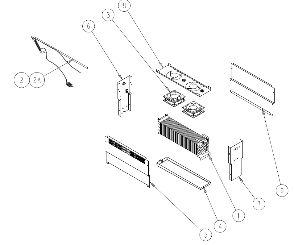
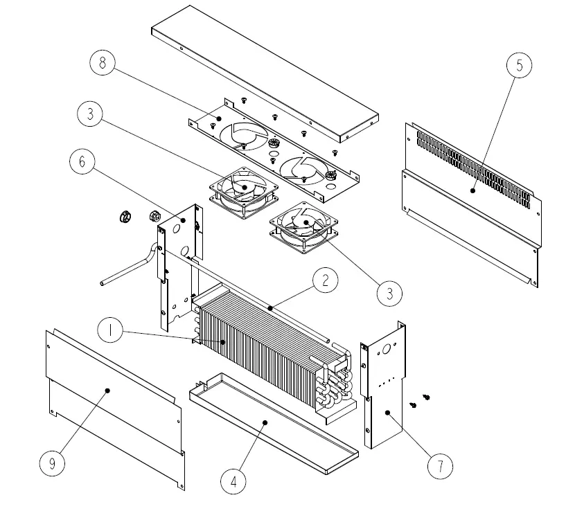
| 8148N-290 | 8260N-290 | 8268N-290 | 8383N-290 | 8395N-290 | 84111N-290 | 8148W-290 | 8268W-290 | 8395W-290 | |||
| ITEM | SERVICE PART | DESCRIPTION | |||||||||
| 1 | RF COI107 | EVAPORATOR COIL | X | X | X | X | X | X | X | X | X |
| 2 | RP CAP1804 | CAP, TUBE – BASE | – | – | – | X | X | X | – | – | X |
| 2A | RP CAP1803 | CAP, TUBE – BASE | X | X | X | – | – | – | X | X | – |
| 3 | RF FAN1401 | FAN, EVAPORATORS | X | X | X | X | X | X | X | X | X |
| 4 | RP DRP107 | EVAPORATOR DRAIN PAN | X | X | X | X | X | X | X | X | X |
| 5 | RP PNL107-290 | SIDE, COIL, 8000N COMMON | X | X | X | X | X | X | X | X | X |
| 6 | RP PNL108-290 | BACK, COIL, 8000N COMMON | X | X | X | X | X | X | X | X | X |
| 7 | RP PNL109-290 | FRONT, COIL, 8000N COMMON | X | X | X | X | X | X | X | X | X |
| 8 | RP SHD1811 | PLATE, FAN, 8000N COMMON | X | X | X | X | X | X | X | X | X |
| 9 | RP PNL1804 | SIDE, COIL, NO PERF, 8000N COMMON | X | – | – | – | – | – | X | – | – |
* = NOT SHOWN
| 9148W-290 | 9260W-290 | 9272W-290 | |||
| ITEM | SERVICE PART | DESCRIPTION | |||
| 1 | RF COI107 | EVAPORATOR COIL | X | X | X |
| 2 | RP CAP1803 | CAP, TUBE – BASE | X | X | X |
| 3 | RF FAN1401 | FAN, EVAPORATORS | X | X | X |
| 4 | RP DRP107 | EVAPORATOR DRAIN PAN | X | X | X |
| 4A | RP DRP107S | EVAPORATOR DRAIN PAN/STAINLESS STEEL | X | X | X |
| 5 | RP PNL107-290 | SIDE, COIL, 8000N COMMON | X | X | X |
| 6 | RP PNL108-290 | BACK, COIL, 8000N COMMON | X | X | X |
| 7 | RP PNL109-290 | FRONT, COIL, 8000N COMMON | X | X | X |
| 8 | RP SHD1811 | PLATE, FAN, 8000N COMMON | X | X | X |
| 9 | RP PNL1804 | SIDE, COIL, NO PERF, 8000N COMMON | X | – | – |
* = NOT SHOWN
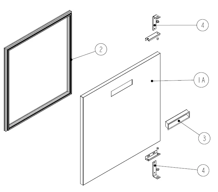
| 8148N-290 | 8260N-290 | 8268N-290 | 8383N-290 | 8395N-290 | 84111N-290 | 8148W-290 | 8268W-290 | 8395W-290 | |||
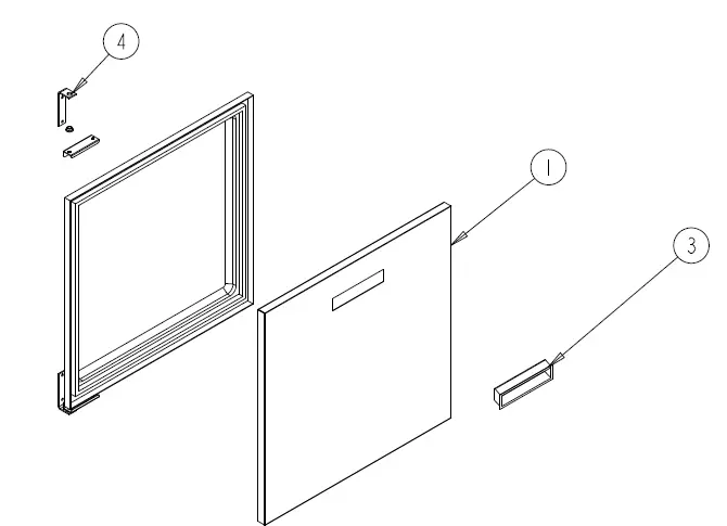
| ITEM | SERVICE PART | DESCRIPTION | |||||||||
| 1 | RF DOR0321 | DOOR HINGED LEFT, 21″ | – | – | – | X | – | X | – | – | – |
| 1A | RF DOR0320 | DOOR HINGED RIGHT, 21″ | – | – | – | X | – | X | – | – | – |
| 1B | RF DOR0323 | DOOR HINGED LEFT, 24″ | – | X | – | X | – | X | – | – | – |
| 1C | RF DOR0322 | DOOR HINGED RIGHT, 24″ | – | X | – | X | – | X | – | – | – |
| 1D | RF DOR0324 | DOOR HINGED LEFT, 27″ | X | – | X | – | X | – | X | – | X |
| 1E | RF DOR0325 | DOOR HINGED RIGHT, 27″ | X | – | X | – | X | – | X | – | X |
| 2* | IN GSK9902 | GASKET, 18.5″ X 24.5″ PUSH IN | – | – | – | X | – | X | – | – | – |
| 2A* | IN GSK1025 | GASKET, 21.75″ X 24.5″ PUSH IN | – | X | – | X | – | X | – | – | – |
| 2B* | IN GSK1030 | GASKET, 24.5″ X 24.5″ PUSH IN | X | – | X | – | X | – | X | – | X |
| 3 | HD HDL0103 | DOOR HANDLE (recessed) | X | X | X | X | X | X | X | X | X |
| 4 | RP HNG9900 | HINGE ASSY, UNIVERSAL, LEFT/RIGHT | X | X | X | X | X | X | X | X | X |
| 4A | RP HNG026 | HINGE, STRAP L BRACKET TOP/BOTTOM | X | X | X | X | X | X | X | X | X |
| 4B | RP HNG027 | HINGE, BOTTM l BRACKET W/ COLLOR | X | X | X | X | X | X | X | X | X |
| 4C | RP HNG023 | HINGE, TOP L BRACKET W/O | X | X | X | X | X | X | X | X | X |
| 4D | RP HNG034 | HINGE, TOP DOOR LH CHANNEL | X | X | X | X | X | X | X | X | X |
| 4E | RP HNG035 | HINGE, TOP DOOR RH CHANNEL | X | X | X | X | X | X | X | X | X |
| 5* | HD BSH050 | BUSHING, NYLON DOOR | X | X | X | X | X | X | X | X | X |
| 6* | RP HNG025 | HINGE, SPRING LOAD ASSEMBLY | X | X | X | X | X | X | X | X | X |
* = NOT SHOWN
| 9148W-290 | 9260W-290 | 9272W-290 | |||
| ITEM | SERVICE PART | DESCRIPTION | |||
| 1 | RP DOR0323 | DOOR HINGED LEFT, 24″ | – | X | – |
| 1A | RP DOR0322 | DOOR HINGED RIGHT, 24″ | – | X | – |
| 1B | RP DOR0324 | DOOR HINGED LEFT, 27″ | X | – | X |
| 1C | RP DOR0325 | DOOR HINGED RIGHT, 27″ | X | – | X |
| 2 | IN GSK1025 | GASKET, 21.75″ X 24.5″ PUSH IN | – | X | – |
| 2A | IN GSK1030 | GASKET, 24.5″ X 24.5″ PUSH IN | X | – | X |
| 3 | HD HDL0103 | DOOR HANDLE (recessed) | X | X | X |
| 4 | RP HNG9900 | HINGE ASSY, UNIVERSAL, LEFT/RIGHT | X | X | X |
| 4A | RP HNG026 | HINGE, STRAP L BRACKET TOP/BOTTOM | X | X | X |
| 4B | RP HNG027 | HINGE, BOTTM l BRACKET W/ COLLOR | X | X | X |
| 4C | RP HNG023 | HINGE, TOP L BRACKET W/O | X | X | X |
| 4D | RP HNG034 | HINGE, TOP DOOR LH CHANNEL | X | X | X |
| 4E | RP HNG035 | HINGE, TOP DOOR RH CHANNEL | X | X | X |
| 5* | HD BSH050 | BUSHING, NYLON DOOR | X | X | X |
| 6* | RP HNG025 | HINGE, SPRING LOAD ASSEMBLY | X | X | X |
* = NOT SHOWN
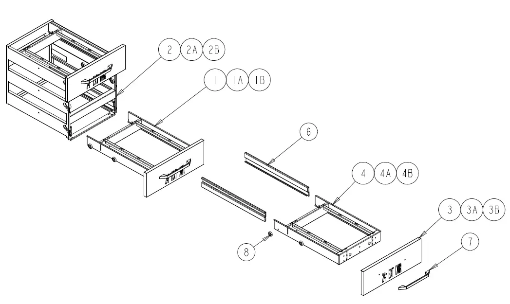
| 8148N-290 | 8260N-290 | 8268N-290 | 8383N-290 | 8395N-290 | 84111N-290 | 8148W-290 | 8268W-290 | 8395W-290 | |||
| ITEM | SERVICE PART | DESCRIPTION | |||||||||
| 1 | RP DRW0206 | DRAWER ASSEMBLY – 21″ | – | – | – | X | – | X | – | – | – |
| 1A | RP DRW0201PT | DRAWER ASSEMBLY – 24″ | – | X | – | X | – | X | – | – | – |
| 1B | RP DRW0202 | DRAWER ASSEMBLY – 27″ | X | – | X | – | X | – | X | – | X |
| 2 | RP MOD050A | DRAWER CARTRIDGE – 21″ | – | – | – | X | – | X | – | – | – |
| 2A | RP MOD030A | DRAWER CARTRIDGE – 24″ | – | X | – | X | – | X | – | – | – |
| 2B | RP MOD029A | DRAWER CARTRIDGE – 27″ | X | – | X | – | X | – | X | – | X |
| 3 | RF FRT9903 | DRAWER FRONT – 21″ | – | – | – | X | – | X | – | – | – |
| 3A | RF FRT9904 | DRAWER FRONT – 24″ | – | X | – | X | – | X | – | – | – |
| 3B | RF FRT9905 | DRAWER FRONT – 27″ | X | – | X | – | X | – | X | – | X |
| 4 | RP FRM0301 | DRAWER FRAME – 21″ | – | – | – | X | – | X | – | – | – |
| 4A | RP FRM0302 | DRAWER FRAME – 24″ | – | X | – | X | – | X | – | – | – |
| 4B | RP FRM0303 | DRAWER FRAME – 27″ | X | – | X | – | X | – | X | – | X |
| 5* | IN GSK9903 | DRAWER GASKET – 18.75″ | – | – | – | X | – | X | – | – | – |
| 5A* | IN GSK1041 | DRAWER GASKET – 21.75″ | – | X | – | X | – | X | – | – | – |
| 5B* | IN GSK1046 | DRAWER GASKET – 24.75″ | X | – | X | – | X | – | X | – | X |
| 6 | RP TRK05SM | DRAWER TRACKS (1L & 1R) | X | X | X | X | X | X | X | X | X |
| 7 | HD HDL130 | DRAWER HANDLE | X | X | X | X | X | X | X | X | X |
| 8 | HC BRG210 | DRAWER BEARING | X | X | X | X | X | X | X | X | X |
| 9* | FA SCW5002 | DRAWER BEARING BOLT | X | X | X | X | X | X | X | X | X |
* = NOT SHOWN
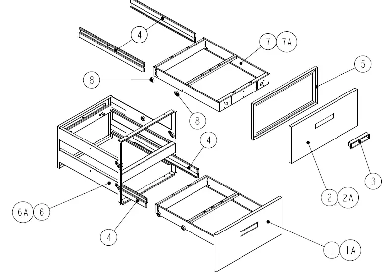
| 9148W-290 | 9260W-290 | 9272W-290 | |||
| ITEM | SERVICE PART | DESCRIPTION | |||
| 1 | RP FRT0304 | DRAWER FRONT – BOTTOM – 24″ | – | X | – |
| 1A | RP FRT0306 | DRAWER FRONT – BOTTOM – 27″ | X | – | X |
| 2 | RP FRT0303 | DRAWER FRONT – TOP – 24″ | – | X | – |
| 2A | RP FRT0305 | DRAWER FRONT – TOP – 27″ | – | – | – |
| 3 | HD HDL0130 | DRAWER HANDLE | X | X | X |
| 4 | RP TRK05SM | DRAWER TRACKS (1L & 1R) | X | X | X |
| 5* | IN GSK1042 | DRAWER GASKET – 24″ Top | – | X | – |
| 5A* | IN GSK1043 | DRAWER GASKET – 24″ Bottom | – | X | – |
| 5B* | IN GSK1048 | DRAWER GASKET – 27″ Top | X | – | X |
| 5C* | IN GSK1047 | DRAWER GASKET – 27″ Bottom | X | – | X |
| 6 | RP MOD1701A | DRAWER CARTRIDGE – 24″ | – | X | – |
| 6A | RP MOD1603A | DRAWER CARTRIDGE – 27″ | X | – | X |
| 7 | RP FRM0103 | DRAWER FRAME – 24″ | – | X | – |
| 7A | RP FRM127E | DRAWER FRAME – 27″ | X | – | X |
| 8 | HD BRG210 | DRAWER BEARING | X | X | X |
| 9* | FA SCW5002 | DRAWER BEARING BOLT | X | X | X |
| 7 | HD HDL130 | DRAWER HANDLE | X | X | X |
| 8 | HC BRG210 | DRAWER BEARING | X | X | X |
| 9* | FA SCW5002 | DRAWER BEARING BOLT | X | X | X |
* = NOT SHOWN
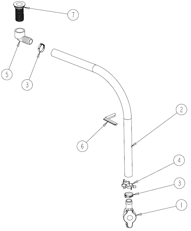
| 8148N-290 | 8260N-290 | 8268N-290 | 8383N-290 | 8395N-290 | 84111N-290 | 8148W-290 | 8268W-290 | 8395W-290 | 9148W-290 | 9260W-290 | 9272W-290 | |||
| ITEM | SERVICE PART | DESCRIPTION | ||||||||||||
| 1 | PB VLV1803 | VALVE, GREEN BACK, 25 MM | X | X | X | X | X | X | X | X | X | X | X | X |
| 2 | PL TBG1801 | TUBING, 1” VINYL, BLACK | X | X | X | X | X | X | X | X | X | X | X | X |
| 3 | HD CLM1801 | CLAMP, 1-1/4” OETIKER | X | X | X | X | X | X | X | X | X | X | X | X |
| 4 | HD CLP1902 | CLIP, SPRING, 1 TO 1-7/8 NICKEL PLATED STEEL | X | X | X | X | X | X | X | X | X | X | X | X |
| 5 | PB ELB1801 | ELBOW, 90 DEG | X | X | X | X | X | X | X | X | X | X | X | X |
| 6 | EL GRM1801 | GROMMET, PUSHON, DRAIN ASSY | X | X | X | X | X | X | X | X | X | X | X | X |
| 7 | HD DRN1702 | DRAIN, ABS, GRAY, 1.375”, 1.00” NPS X 2.875” LG W/NUT & WASHER | X | X | X | X | X | X | X | X | X | X | X | X |
* = NOT SHOWN
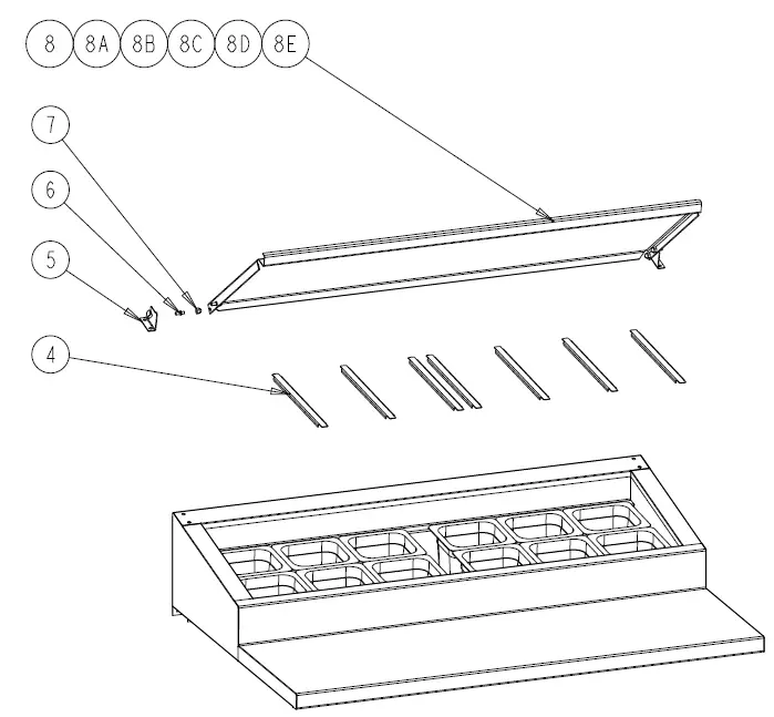
| 8148N-290 | 8260N-290 | 8268N-290 | 8383N-290 | 8395N-290 | 84111N-290 | |||
| ITEM | SERVICE PART | DESCRIPTION | ||||||
| 1* | HD PIN107 | PIN, THREADED SOUTHCO | X | X | X | X | X | X |
| 2* | HD PIN107I | INSERT, THREADED SOUTCHO | X | X | X | X | X | X |
| 3* | HD PIN001 | PIN, KEY PAN RAIL | X | X | X | X | X | X |
| 4 | RP DSN001 | DRAIN SCREEN, 2″ | X | X | X | X | X | X |
| 5 | RP HNG006 | HINGE, PAN COVER SET OF 2 | X | X | X | X | X | X |
| 6 | HD PIN0101 | PIN, LOCATING 0.875 LENGTH | X | X | X | X | X | X |
| 7 | FA NUT0403SS | NUT, 1/4-20 CAP NUT 18-8 SS | X | X | X | X | X | X |
| 8 | RP PCR0115 | COVER, HINGED PAN | X | – | – | – | – | – |
| 8A | RC PCR0117 | COVER, HINGED PAN | – | X | – | – | – | – |
| 8B | RC PCR0118 | COVER, HINGED PAN | – | – | X | – | – | – |
| 8C | RC PCR0114 | COVER, HINGED PAN | – | – | – | X | – | – |
| 8D | RC PCR0115 | COVER, HINGED PAN | – | – | – | – | X | – |
| 8E | RC PCR0116 | COVER, HINGED PAN | – | – | – | – | – | X |
* = NOT SHOWN
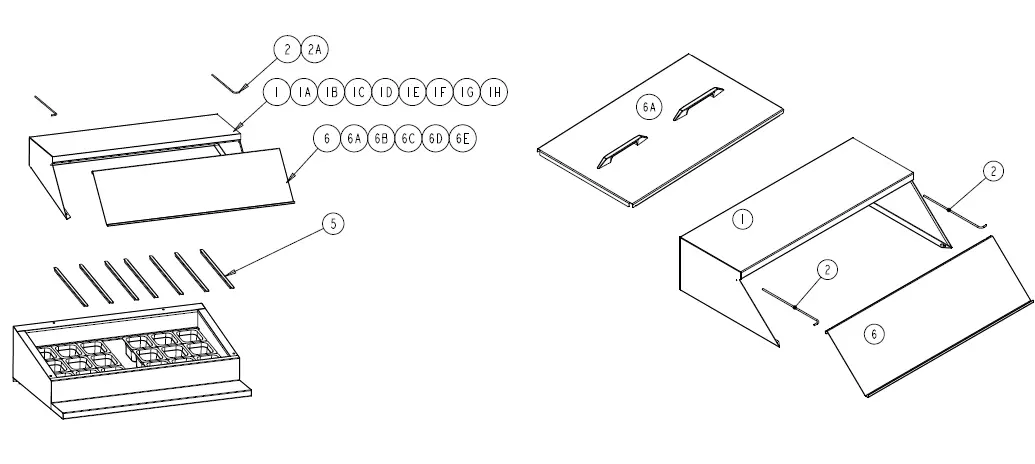
| 8148N-290 | 8260N-290 | 8268N-290 | 8383N-290 | 8395N-290 | 84111N-290 | 8148W-290 | 8268W-290 | 8395W-290 | 9148W-290 | 9260W-290 | 9272W-290 | |||
| ITEM | SERVICE PART | DESCRIPTION | ||||||||||||
| 1 | RP HOD0101 | HOOD COVER | X | – | – | – | – | – | – | – | – | X | – | – |
| 1A | RPHOD1801 | HOOD COVER | – | – | – | – | – | – | X | – | – | – | X | – |
| 1B | RP HOD0301 | HOOD COVER | – | X | – | – | – | – | – | – | – | – | – | X |
| 1C | RP HOD0202 | HOOD COVER | – | – | X | – | – | – | – | – | – | – | – | – |
| 1D | RP HOD1802 | HOOD COVER | – | – | – | – | – | – | – | X | – | – | – | – |
| 1E | RP HOD0407 | HOOD COVER | – | – | – | X | – | – | – | – | – | – | – | |
| 1F | RP HOD0310 | HOOD COVER | – | – | – | – | X | – | – | – | – | – | – | – |
| 1G | RP HOD1803 | HOOD COVER | – | – | – | – | – | – | – | – | X | – | – | – |
| 1H | HP HOD0609 | HOOD COVER | – | – | – | – | – | X | – | – | – | – | – | – |
| 2 | HD ROD100 | HOOD COVER, ROD W/ SINGLE BEND | X | – | – | – | X | – | X | – | X | X | – | – |
| 2A | HD ROD200 | HOOD COVER, ROD W/ DOUBLE BEND | – | – | – | – | X | – | – | – | X | – | – | – |
| 3* | HD PIN107 | PIN, THREADED SOUTHCO | X | X | X | X | X | X | X | X | X | X | X | X |
| 4* | HD PIN107I | INSERT, THREADED SOUTCHO | X | X | X | X | X | X | X | X | X | X | X | X |
| 5* | RP DSN001 | DRAIN SCREEN, 2″ | X | X | X | X | X | X | X | X | X | X | X | X |
| 6 | RP LID048 | COVER (IMAGE ON LEFT) | X | – | – | – | – | – | – | – | – | – | – | – |
| 6 | RP HNG017 | SLIDE BACK COVER (IMAGE ON RIGHT) | – | – | – | – | – | – | – | – | – | X | X | X |
| 6A | RP LID1502 | COVER | – | X | – | – | – | – | – | – | – | – | X | – |
| 6B | RP LID068 | COVER | – | – | X | – | – | – | – | – | – | – | – | X |
| 6C | RP LID083 | COVER | – | – | – | X | – | – | – | – | – | – | – | – |
| 6D | RP LID095 | COVER | – | – | – | – | X | – | – | – | – | – | – | – |
| 6E | RP LID111 | COVER | – | – | – | – | – | X | – | – | – | – | – | – |
| 6F | RP LID1801 | COVER | – | – | – | – | – | – | X | – | – | – | – | – |
| 6G | RP LID1802 | COVER | – | – | – | – | – | – | – | X | – | – | – | – |
| 6H | RP LID1803 | COVER | – | – | – | – | – | – | – | – | X | – | – | – |
| 7* | HD PIN001 | PIN, KEY PAN RAIL | – | – | – | – | – | – | X | X | X | – | – | – |
* = NOT SHOWN
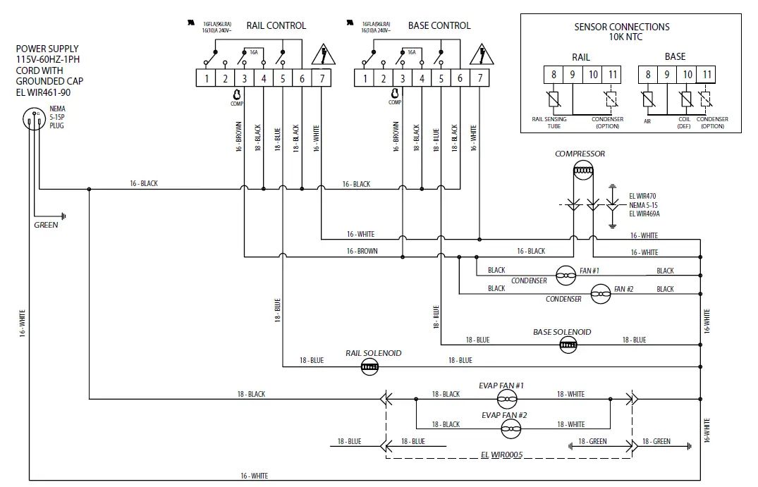
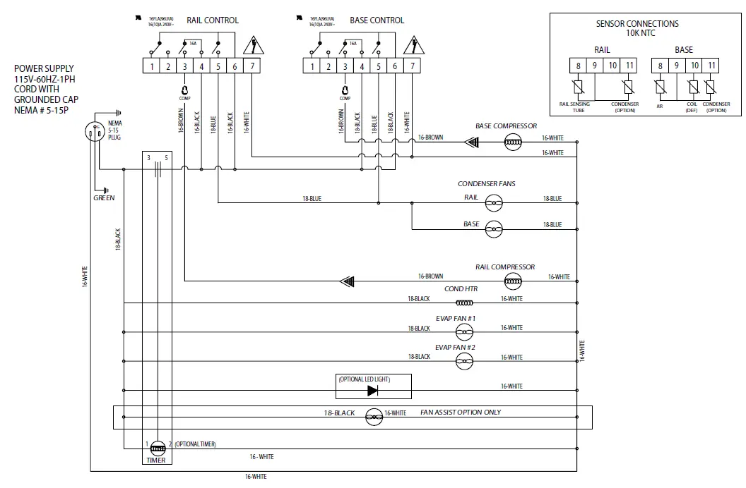
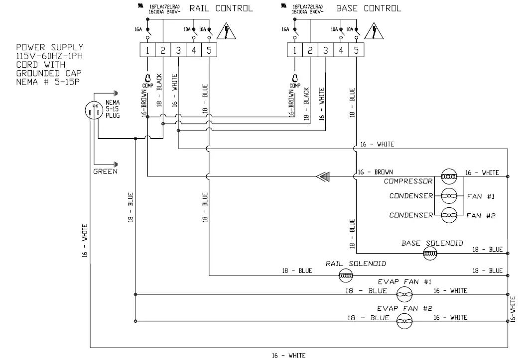
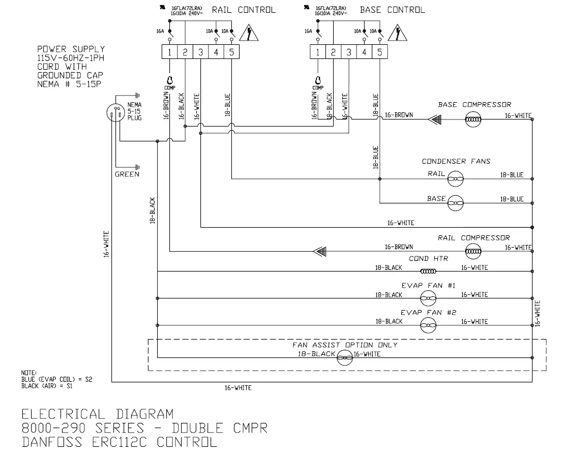
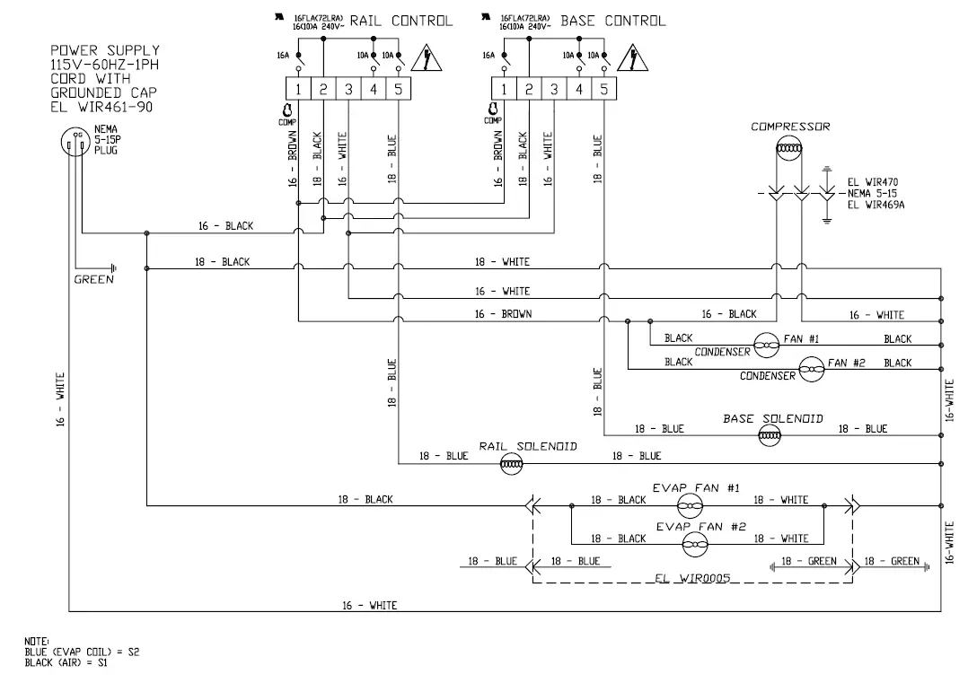
Wiring Diagram


Service Log
| Model No: | Purchased From: |
| Serial No: | Location: |
| Date Purchased: | Date Installed: |
| Purchase Order No: | For Service Call: |
| Date | Maintenance Performed | Performed By |


