TZONE TZ-THT01 Hvac Temperature Transmitter
Product Description
Product Description
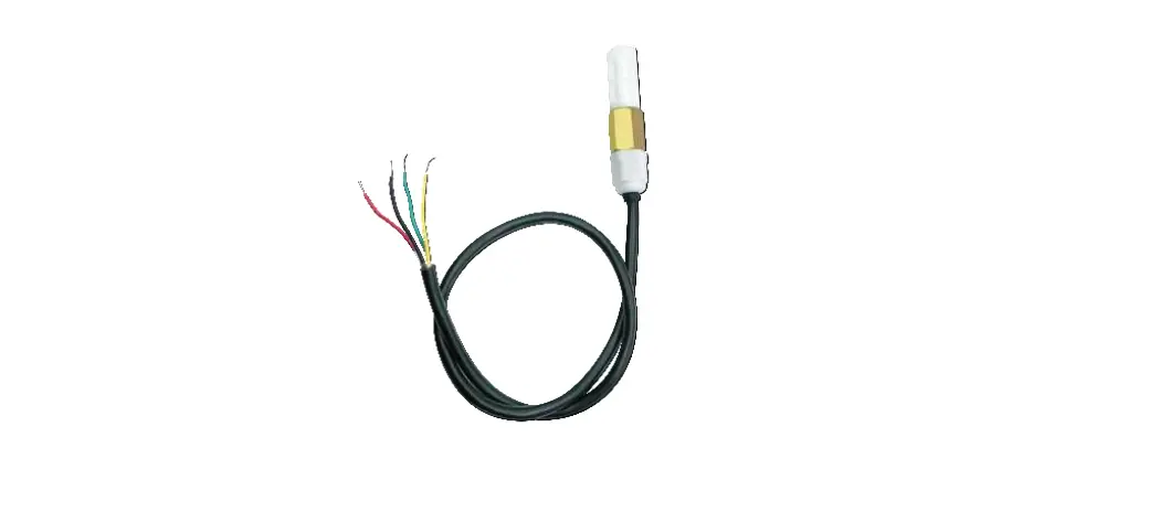
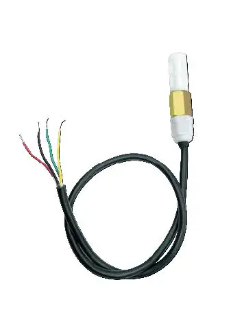
TZ-THT01 temperature and humidity sensor has the characteristics of small size, stable operation, using standard Modbus-RTU communication protocol, and is suitable for use in various industrial environments.
Features
- Four-wire interface with VCC/GND/RS485-A/RS485-B, simple and reliable, easy to expand
- RS485 communication method
- Data transmission based on Modbus-RTU industrial control bus protocol, with reliable performance and good compatibility
- Small size, easy to install
- Moisture-proof treatment for agricultural application environment, suitable for agricultural, industrial and other environments
- Serial port configuration:
Baud rate: 1200/2400/4800/9600/19200/38400/57600;
Data bits: 8 bits; not configurable
Check: No check; not configurable
Stop bit: 1 bit; not configurable
After the configuration is completed, send a soft reset command or power off and restart to take effect;
Characteristic
- Temperature and humidity sensor: SHT30
- Measuring temperature range: -40℃ ~ +125℃
Resolution: 0.1℃
Accuracy: ±0.2℃ - Range of working temperature: -40℃ ~ +80℃
- Humidity measurement range: 0% ~ 100% (RH) Relative humidity resolution: 0. 1%RH Accuracy: ±2%RH( 25℃)
- Working humidity range: 0% ~ 100% (RH);
- Power input: 5-24V DC;
- Working current: 5mA
- Line length: 1m
- Waterproof level: IP65
- Communicate protocol: Modbus-RTU
- Device address code configurable range: 1~254
Interface Definition
- VCC: Power supply is positive, recommended 12VDC; Red Line
- GND: Power supply is negative, signal ground; Black Line
- RS485-A: Communication differential signal; Yellow Line
- RS485-B: Communication differential signal; Green Line
Factory Settings
- Serial Port: Baud rate 9600, Data bits:8 bits, Stop bi: 1 bit, No parity bit;
- Device address: Default address mode 0x01; (“0x**” represents hexadecimal numbers)
Protocol
For the Modbus-RTU protocol, please refer to the relevant information, here is only a brief introduction.
Data frame format
| Start bit | Data bit | Parity bit | Stop bit |
| 1 | 8 | 0 | 1 |
Note: The above is the default format of the sensor. If you need other formats, please specify when ordering.
RTU message frame format
THT-01 follows the RTU information frame protocol. In order to ensure the integrity of the information frame, a pause time of 3.5 characters or more is required at the beginning and end of each information frame (T1-T2-T3-T4, this time can be based on the wave Calculated by special rate), each byte of the information frame needs to be transmitted continuously. If there is a pause time greater than 1.5 characters, the sensor will treat it as invalid information and will not respond.
Information frame format
| Start | Address | Function code | Data area | CRC check | End |
| T1-T2-T3-T4 | 1byte | 1byte | N byte | 2byte | T1-T2-T3-T4 |
2.4 Register Definition
| Register Address | Meaning | Description | Read and write |
| 0 | Temperature | The unit is 0.1 degree, MSB First, complement format, 7FFF H means the sensor is abnormal | Read only |
| 1 | Relative humidity | The unit is 0.1%, MSB First, complement format, 7FFF H means the sensor is abnormal | Read only |
| 2 | Reserved 1 | Read only | |
| 3 | Reserved 2 | Read only | |
| 4 | Address code | The settable range is 1-254 | Can read and write |
| 5 | Baud rate | Support 1200/2400/4800/9600/19200/38400/5760 0 | Can read and write |
| 6 | Hardware version | Read only | |
| 7 | Software version |
|
Address setting
You can specify when ordering, we will preset it for you, or you can modify it by yourself through the configuration software.
Baud rate setting
You can specify when ordering, we will preset it for you, or you can modify it by yourself through the serial port assistant.
Host reads sensor information (function code 03)
The sensor allows the host to use the function code 03 to read the temperature and humidity measurement value of the sensor and other information. The information frame format of the 03 code is as follows:
Host request information frame:
| Field Description | Example |
| Slave address | 01 |
| Function code | 03 |
| Register address high byte | 00 |
| Register address low byte | 00 |
| High byte of query quantity | 00 |
| Low byte of query quantity | 08 |
| CRC check code low byte | 44 |
| CRC check code high byte | 0C |
Sensor response information frame:
| Field Description | Example |
| Slave address | 01 |
| Function code | 03 |
| Return the number of bytes | 10 |
| Temperature data high byte | 00 |
| Temperature data low byte | FA |
| Humidity data high byte | 02 |
| Low byte of humidity data | 58 |
| 1 high byte reserved | 00 |
| 1 low byte reserved | 00 |
| 2 high byte reserved | 00 |
| 2 low byte reserved | 00 |
| Address code high byte | 00 |
| Address code low byte | 01 |
| Baud rate high byte | 25 |
| Baud rate low byte | 80 |
| Hardware version high byte | 06 |
| Hardware version low byte | 00 |
| Software version high byte | 00 |
| Software version low byte | 0A |
| CRC check code low byte | D4 |
| CRC check code high byte | 64 |
- Data analysis:
- Temperature = 00FAH = 250 / 10 = 25.0℃;Humidity = 0258H = 600 / 10 = 60.0%RH;Reserved 1 = 0000H;
- Reserved 2 = 0000H;
- Address code = 0001H = 1;
- Baud rate = 2580H = 9600;
- Hardware version = 0600H;
- Software version = 000AH = 10 = V1.0;
Note! If users only want to read the temperature and humidity or other registers, they only need to read the corresponding registers.
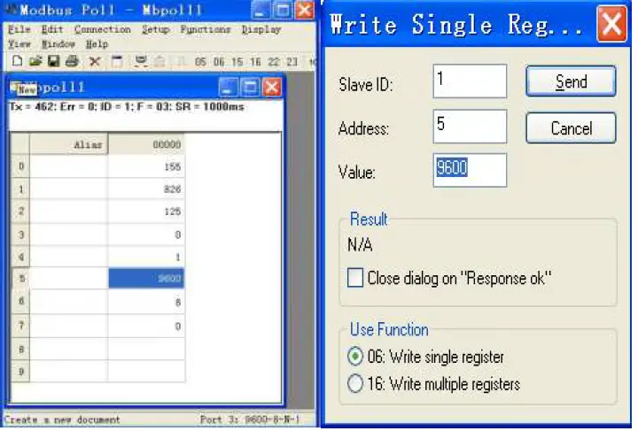
Host setting sensor information (Function Code 06)
This device can currently set the baud rate (register address is 0005H), and the message frame format as follows:
Host request information frame:
| Field description | Example |
| Slave address | 01 |
| Function code | 06 |
| Register address high byte | 00 |
| Register address low byte | 05 |
| Set value high byte | 25 |
| Set value low byte | 80 |
| CRC check code low byte | 82 |
| CRC check code high byte | FB |
Sensor response information frame:
| Field description | Example |
| Slave address | 01 |
| Function code | 06 |
| Register address high byte | 00 |
| Register address low byte | 05 |
| Set value high byte | 25 |
| Set value low byte | 80 |
| CRC check code low byte | 82 |
| CRC check code high byte | FB |
Data analysis: Set the baud rate to 9600
Abnormal response
When the host sends request information to the sensor, various errors may occur. At this time, the sensor sets the highest position of the function code to 1, and then returns an error code. The host can determine whether an error has occurred by detecting whether the highest bit of the function code is 1.
Return format:
| Slave address | Function code | Error code | CRC check |
| 1 byte | 1 byte | 1 byte | 2 byte |
Error code:
- Illegal function code
- Illegal data address
- Illegal data value
CRC check code
RTU mode uses CRC-16 check, the check code occupies 2 bytes, if the check code is wrong, the sensor will ignore the host’s request and not respond.
The calculation method of CRC-16 check code is as follows:
- Preset a 16-bit register as hexadecimal FFFF, call this register CRC register;
- XOR the first 8-bit binary data (the first byte of the information frame) with the lower 8 bits of the 16-bit CRC register, and place the result in the CRC register;
- Shift the content of the CRC register one bit to the right (toward the low bit) and fill the highest bit with 0, check the right shift out position after shift;
- If the shifted out bit is 0, repeat step ③ (shift one bit to the right again), if the shifted out bit is 1, the CRC register is XORed with the polynomial A001 (1010 0000 0000 0001);
- Repeat steps ③ and ④ until the right shift is 8 times, so that the entire 8-bit data has been processed;
- Repeat steps ② to step ⑤ to process the next byte of the message frame;
- After calculating all the bytes of the information frame according to the above steps, the content of the
- CRC register obtained is: 16-bit CRC check code


