VESTA TMST-15ZBS Intruder Aalarm Thermostat User Manual
Introduction
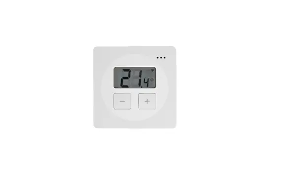
TMST-15-ZBS is a battery powered ZigBee Thermostat. It is designed to be incorporated into household heating and cooling system for home environment control. The Thermostat can be operated manually using the LCD screen and buttons, or accessed remotely via ZigBee network. It features Cooling and Heating modes with temperature set point and automatic schedule for you to control your home environment easily.
The Thermostat utilizes ZigBee technology for wireless signal transmission. ZigBee is a wireless communication protocol that is reliable and has low power consumption and high transmission efficiency. Based on the IEEE802.15.4 standard, ZigBee allows a large amount of devices to be included in a network and coordinated for data exchange and signal transmission
The Thermostat serves as an end device in the ZigBee network. It can be included in the ZigBee network to transmit signal upon activation, but cannot permit any other ZigBee device to join the net.
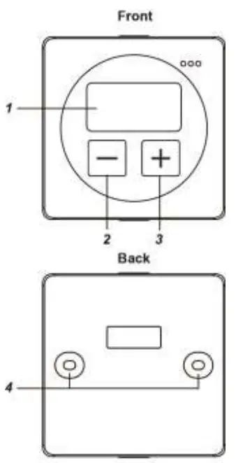
Parts Identification
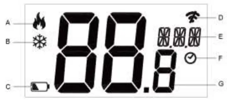
- LCD Display
The LCD displays the following information:
A. Heat mode Icon: When displayed, the Thermostat is under Heat mode.
B. Cool mode Icon: When displayed, the Thermostat is under Cool mode.
C. Low battery Icon: When displayed the Thermostat battery voltage is low.
D. ZigBee network connectivity:
The icon is displayed when Thermostat is not yet learnt into any gateway/panel, or when the device loses connection to current ZigBee network.
E. Mode: Mode Selection, Remote Mode, and Offset
F. Schedule: The Thermostat will execute programmed schedule setting.
G. Temperature Reading / Setpoint - Down (-) Button.
Press to decrease setpoint
Press and hold for 3 seconds to enter programming mode. - Up (+) Buton
Press to increase setpoint.
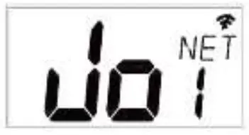
Press and hold for 10 seconds to enter learning mode, and “Joi NET” will be displayed on the LCD screen.
- Wall Mounting Hole

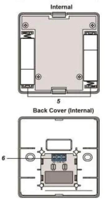
- Battery Compartment
Insert 2 AA Alkaline batteries. - Relay Terminals (Remove Relay Cover to Access) 230V 5A NO/COM/NC relay terminals. Connect to home heating/cooling system.

Features
Battery and Low Battery Detection
The Thermostat uses 2 AA Alkaline batteries as its power source. The Thermostat features Low Battery Detection function. When the battery voltage is low, the Thermostat will transmit Low Battery signal to the coordinator in ZigBee network.
Relay Control
The Thermostat control home heating/cooling system through relay control. Open and flip over the back cover, remove the internal cover on the relay to reveal the terminals for wiring. When wiring the Thermostat, wire the cable through the central opening on the back cover.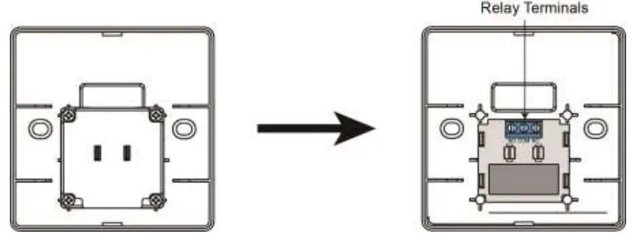
Mode Control
The Thermostat has two operation modes: Local mode and Scheduled mode.
- Local Mode:
Local mode allows adjustment of Thermostat Heat/Cool function and setpoints using thermostat buttons. - Scheduled Mode:
Scheduled mode allows Thermostat mode and setpoint control via Gateway after learning is completed.
To change the operation mode, please refer to “Programming Mode” section for more details.
Heating/Cooling and Setpoint Control
The Thermostat Heating/Cooling and setpoint can only be adjusted locally when Thermostat is set to Local mode.
When under local mode, press the UP (+) or Down (-) button to adjust setpoiont.
When under scheduled mode, use the Gateway/Control Panel to adjust the setpoint remotely.
Heat setpoint range: 9°C ~ 30°C.
Cool setpoint range: 11°C ~ 32°C
Remote Control
After the Thermostat joins a ZigBee network, you can control the Thermostat via ZigBee network coordinator or gateway. Please refer to your ZigBee coordinator/gateway manual for more information.
The following functions are only available for setting via ZigBee coordinator and gateway:
- Schedule:
You can only program Schedule configuration via ZigBee network coordinator/gateway.
Schedule Setting: Up to 5 schedules can be programmed for every weekday with Mode, Setpoint and Start time.
Schedule Control:
Normal – The Thermostat will execute programmed schedule setting accordingly.
Hold – The Thermostat will bypass currently timed schedule and perform the next schedule when it begins
No Schedule – The Thermostat will not execute any set schedule until it is set to Normal again.
Temperature Detection
- The Thermostat has built-in temperature sensors and will display the temperature reading on the LCD display.
- The Thermostat will transmit temperature signals regularly according to setting. The factory default interval is 10 minutes.
- When the temperature changes by +/- 2°C, the Thermostat will also transmit a signal.
- You can also press the ZigBee Network Button once to transmit a temperature signal manually.
Supervision
The Thermostat will transmit a supervision signal every 10 minutes along with the temperature, current mode and set point information to report its condition regularly.
Programming Mode
Step 1. Press and hold Down (-) button for 3 seconds to enter programming mode.
Step 2. There are 3 functions available for programming, including Thermostat Functions, Controlling Remote Relay, and Setpoint
Offset. You can press either UP (+) or Down (-) button to switch modes.
Step 3. After finishing selection, wait for a few seconds for the Thermostat to enter selected mode.
Thermostat Functions (Heating and Cooling):
In this mode, “Pro Mod” will be displayed on the LCD screen.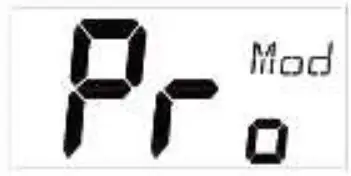
Heating/Cooling modes are available for selection. Press UP (+) button to select Heating and Down (-) button to select Cooling.
Heating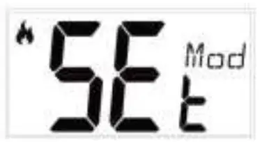
Cooling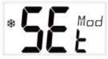
After finishing selection, wait for a few seconds for the Thermostat to quit setting mode automatically. The Thermostat will enter the mode last selected.
Controlling Remote Relay:
In this mode, “Pro RM” will be displayed on the LCD screen.
The Remote Mode allows you to control remote relay via the Control Panel when function enabled. The Thermostat will not control the local relay in Remote Mode.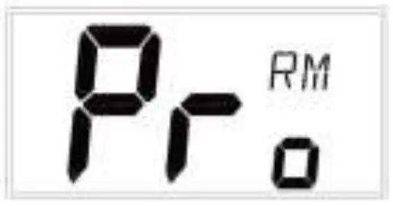
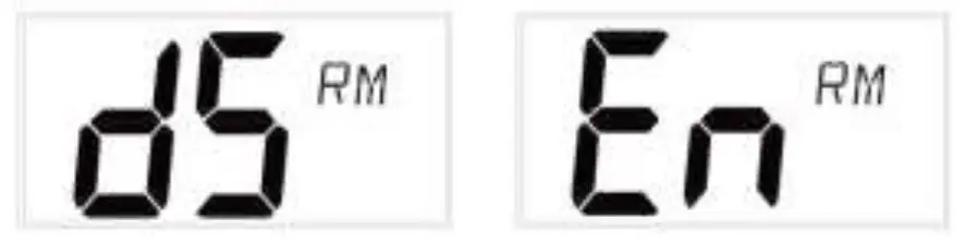
- If remote mode is disabled, “dS RM” will be displayed on the LCD screen.
- If remote mode is enabled, “En RM” will be displayed on the LCD screen.
Setpoint Offset:
In this mode, “Pro OFS” will be displayed on the LCD screen. Setpoint Offset function allows you to compensate the deviation. To calculate setpoint offset, simply subtract room temperature with device temperature. When under local mode, press and hold Down (-) button for 3 seconds to enter programming mode. After finishing selection, wait for a few seconds for the Thermostat to enter mode selection.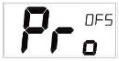
For example: If device temperature is 20°C and room temperature is 18°C, then setpoint offset = 18 – 20 = -2°C.
After setpoint offset is applied, the device will operate according to adjusted temperature.
For example: If device temperature reading is 20°C, setpoint offset is -2°C, the device will operate using 18°C as actual reference.
ZigBee Network Setup
ZigBee Device Guideline
ZigBee Device Guideline
ZigBee is a wireless communication protocol that is reliable and has low power consumption and high transmission efficiency. Based on IEEE802.15.4 standard, ZigBee allows a large amount of devices to be included in a network and coordinated for data exchange and signal transmission.
Due to the fundamental structure of ZigBee network, ZigBee device will actively seek and join network after powering on. Since performing a task in connecting network may consume some power, it is required to follow the instructions to avoid draining battery of a ZigBee device
- Ensure your ZigBee network router or coordinator is powered on before inserting battery into the ZigBee device.
- Ensure the ZigBee network router or coordinator is powered on and within range while a ZigBee device is in use.
- Do not remove a ZigBee device from the ZigBee network router or coordinator without removing the battery from a ZigBee device.
Joining the ZigBee Network
As a ZigBee device, the Thermostat needs to join a ZigBee network to for user to control it remotely. Please follow the steps bellow to join the Thermostat into the ZigBee network.
- Remove the Thermostat back cover and insert 2 AA Alkaline batteries to power up the Thermostat.
- Press and hold the ZigBee network button for 10 seconds then release to join ZigBee network. Please make sure the permit-join feature on the router or coordinator of your ZigBee network is enabled.
- Wait for several seconds for the Thermostat to join ZigBee network, if the Thermostat successfully joins a network, the ZigBee connection icon will appear on LCD display.
- After joining the ZigBee network, the Thermostat will be registered in the security system in the network automatically. Please check the security system control panel or CIE (Control and Indicating Equipment) to confirm if joining and registration is successful.
- After joining the ZigBee network, if the Thermostat loses connection to current ZigBee network, the ZigBee connection icon will disappear after 10 minutes. Please check the ZigBee network condition and Thermostat signal range to correct the situation.
Removing Device from ZigBee Network (Factory Reset)
To remove the Thermostat from current ZigBee network, the Thermostat must be put to Factory Reset to complete device removal. Factory Reset function will clear the Thermostat of its stored setting information and prompt the device to search for new ZigBee network.
Before removing device, make sure the Thermostat is within current ZigBee network signal range
- Press and hold the function button for 10 seconds, then release the button to reset Thermostat.
- Upon reset, the Thermostat will clear current ZigBee network setting and transmit signal to ZigBee coordinator to remove itself from current ZigBee network. It will then actively search for available ZigBee network again and join the network automatically
Installation
The Thermostat is designed to be wall mounted using the mounting holes on the back cover.
- Before mounting, make sure to complete relay wiring through the opening on the back cover first.
- Use the mounting holes on the back cover as template to mark mounting location on the wall.
- Drill holes on the wall and insert wall plug if required, screw the back cover onto the mounting location.
- Place the Thermostat main body on the back cover, installation is complete.
Apendix(For developers only.)
Thermostat Cluster ID
| Device ID: ZCL_HA_DEVICEID_THERMOSTAT 0x0301Endpoint: 0x01 | |
| Server Side | Client Side |
| Man datory | |
| Basic (0x0000) | Identify(0x0003) |
| Power Configure(0x0001) | On/Off(0x0006) |
| Identify(0x0003) | Time(0x000A) |
| HVAC THERMOSTAT (0x0201) | |
| Diagnostics (0x0B05) | |
| Optional | |
| None | None |
Attribute of Basic Cluster Information
| Identifier | Name | Type | Range | Access | Default | Mandatory/ Optional |
| 0x0000 | ZCLVersion | Unsigned 8-bit integer | 0x00 –0xff | Read only | 0x01 | M |
| 0x0001 | ApplicationVersion | Unsigned 8-bit integer | 0x00 –0xff | Read only | 0x00 | O |
| 0x0003 | HWVersion | Unsigned 8-bit integer | 0x00 –0xff | Read only | 0 | O |
| 0x0004 | ManufacturerName | Character String | 0 – 32 bytes | Read only | VestaTechnology | O |
| 0x0005 | ModelIdentifier | Character | 0 – 32 bytes | Read only | (Model | O |
| String | Version) | |||||
| 0x0006 | DateCode | Character String | 0 – 16 bytes | Read only | O | |
| 0x0007 | PowerSource | 8-bit | 0x00 –0xff | Read only | M | |
| 0x0010 | LocationDescription | Character String | 0 – 32 bytes | Read / Write | O | |
| 0x0011 | PhysicalEnvironment | 8-bit | 0x00 –0xff | Read / Write | 0x00 | O |
| 0x0012 | DeviceEnabled | Boolean | 0x00 –0x01 | Read / Write | 0x01 | M |
Attribute of Power Configure Cluster Information
| Identifier | Name | Type | Range | Access | Default | Mandatory/ Optional |
| 0x0035 | BatteryAlarmMask | map8 | 0b0000 000x | Read / Write | 0b0000 0000 | O |
Attribute of Identify Cluster Information
| Identifier | Name | Type | Range | Access | Default | Mandatory/ Optional |
| 0x0000 | IdentifyTime | Unsigned 16-bit integer | 0x00 –0xffff | Read / Write | 0x0000 | M |
Attribute of Thermostat Cluster Information
| Identifier | Name | Type | Range | Access | Default | Mandatory/ Optional |
| 0x0000 | LocalTemperature | 16-bit | 0x954d – 0x7fff | Read only | 0x0000 | M |
| 0x0003 | AbsMinHeatSetpointLimit | 16-bit | 0x954d – 0x7fff | Read only | 0x01F4 | O |
| 0x0004 | AbsMaxHeatSetpointLimit | 16-bit | 0x954d – 0x7fff | Read only | 0x0DAC | O |
| 0x0005 | AbsMinCoolSetpointLimit | 16-bit | 0x954d – 0x7fff | Read only | 0x01F4 | O |
| 0x0006 | AbsMinCoolSetpointLimit | 16-bit | 0x954d – 0x7fff | Read only | 0x0DAC | O |
| 0x0009 | HVACSystemTypeConfiguration | map8 | 0b00xx xxxx | Read / Write | 0b00000000 | O |
| 0x0010 | LocalTemperatureCalibration | 8-bit | 0xE7 – 0x19 | Read / Write | 0x00 | O |
| 0x0011 | OccupiedCoolingSetpoint | 16-bit | Min Cool Setpoint Limit – Max Cool Setpoint Limit | Read / Write | 0x0A28 | M |
| 0x0012 | OccupiedHeatingSetpoint | 16-bit | Min Heat SetpointLimit – Max Heat Setpoint Limit | Read / Write | 0x07D0 | M |
| 0x001B | ControlSequenceOfOperation | 8-bit Enumeration | 0x00 – 0x05 | Read / Write | 0x04 | M |
| 0x001C | SystemMode | 8-bit Enumeration | 0x00 – 0x09 | Read / Write | 0x04 | M |
| 0x0020 | StartOfWeek | 8-bit Enumeration | 0x00 – 0x06 | Read | – | O |
| 0x0021 | NumberOfWeeklyTransitions | uint8 | 0x00 – 0xff | Read | N/A | O |
| 0x0022 | NumberOfDailyTransitions | uint8 | 0x00 – 0xff | Read | N/A | O |
| 0x0023 | TemperatureSetpointHold | 8-bit Enumeration | 0x00 – 0x01 | Read / Write | 0x00 | O |
| 0x0024 | TemperatureSetpointHoldDurati on | uint16 | 0xffff – 0x05a0 | Read / Write | 0xffff | O |
| 0x0025 | ThermostatProgrammingOperati onMode | map8 | 0b00xx xxxx | Read / Write | 0b00000000 | O |
| 0xFF01 | ThermostatRemoteControlMode | map8 | 0b0000 000x | Read /Write | 0b00000000 | O |
Attribute of Diagnostics Cluster Information
| Identifier | Name | Type | Range | Access | Default | Mandatory/ Optional |
| 0x011C | LastMessageLQI | 8-bit | 0x00 – 0xFF | Read | 0x00 | O |
| 0x011D | LastMessageRSSI | 8-bit | 0x00 – 0xFF | Read | 0x00 | O |


