AQD-WM300 RS485 Indoor Air Quality Controller
User Manual
AQD-WM300 (RS485) Indoor Air Quality Controller
Date: March 2021 Doc Version:1.0 English
AQD-WM300 (RS485)
Applications
- Residential ventilation system.
- Business ventilation system
- Industrial ventilation system
Description
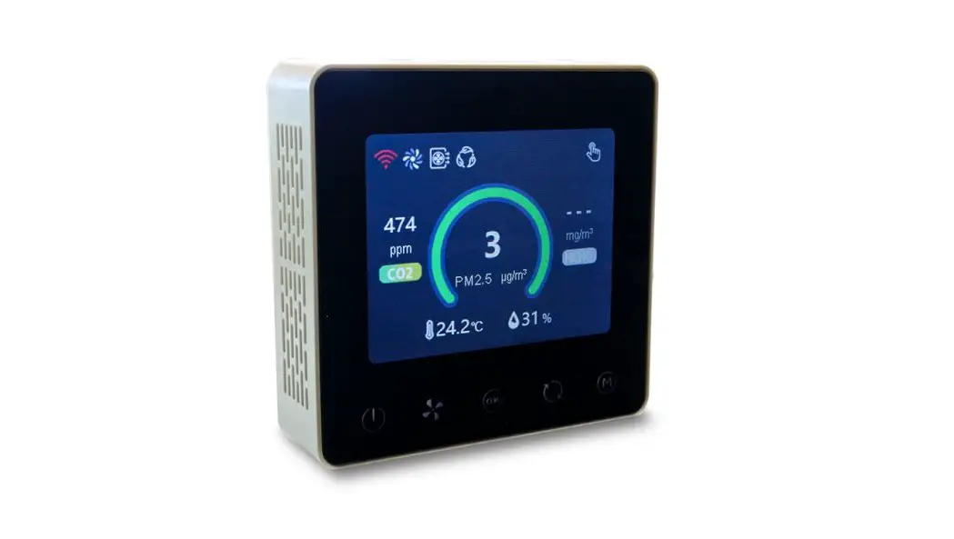
AQD-WM300 (RS485) is an indoor air quality controller with screen provides customers with visual indoor air quality readings, such as PM2.5, CO2, temperature, humidity, etc. It is widely used in residential, commercial and industrial applications, and can effectively improve air quality and create a healthy, comfortable, efficient, environmentally friendly, energy-saving living and working environment.
Features
Compatible with embedded and wall-mounted fixing methods; Compatible with push-button and touch-screen operation; Using standard 86 box size, thickness <24mm; PM2.5, CO2, temperature and humidity etc., multiple sensors can be optionally selected.
Working Principle
The built-in dust sensor uses the principle of laser scattering technology to detect the indoor PM2.5 mass concentration in real time (g/m³). The built-in carbon dioxide sensor uses the principle of NDIR technology to detect indoor CO2 concentration in real time (ppm). The temperature and humidity sensor use capacitor resistance material to detect the indoor temperature (° C) and humidity (%) in real time.
Specifications
Working principle | CO2:NDIR |
Measurement range | PM2.5:0~1000μg/m³ |
PM2.5 Measurement accuracy | ≤ 100μg/m³:±10μg/m³ |
CO2 Measurement accuracy | ±(50ppm+5% reading)@ 0~50℃ |
Temperature Measurement accuracy | ±1ºC |
Humidity Measurement accuracy | ±8%RH |
PM Response time T90 | ≤8s |
CO2 Response time T90 | <120s |
Working condition | -10~50ºC, 0~95%RH(Non-condensing) |
Storage condition | -20~60ºC, 0~95%RH(Non-condensing) |
Working voltage | DC 12V |
Working current | <140mA |
Standby current | ≤80mA |
Signal Output | RS485 |
Installation hole distance | 60mm(standard) |
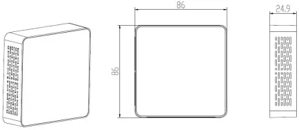
Dimension | 86*86*24.9 mm |
Lifetime | PM:≥5 years |
Dimensions and Interface Definition
1. Dimensions (Unit: mm, tolerance ±0.2 mm)
1. Pin definition
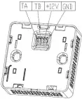
| Nº | Pin | Description |
| 1 | TA | Communication port (RS485_TA) |
| 2 | TB | Communication port (RS485_TB) |
| 3 | +12V | Power input (+12V) |
| 4 | GND | Power input (GND) |
Dimensions and Interface Definition
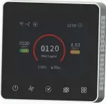
Parameter Range corresponding to color LIST | |||
Gas | Level | Range | Color |
PM2.5 | Good | 0~75 | |
Just so so | 75~115 | ||
Bad | ≥115 | ||
CO2 | Good | 0~600 | |
Just so so | 600~1000 | ||
Bad | ≥1000 | ||
Installation Instructions
Step 1: Fix the wall mounted bracket with screws on the 86 box which in the embedded wall, as shown below: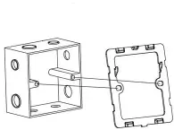
Step 2: Connecting Cable, connect the corresponding cable to the controller’s RS485 interface according to the interface definition, as shown below: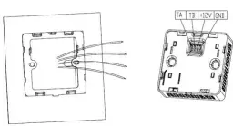
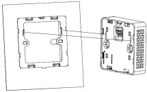
Step 3: Match the two holes in the controller with the hooks in the wall mount bracket and slide the controller down to ensure that the controller is tightly locked with the bracket.
Precautions for use
Do not place the controller in an environment where the ambient temperature is too high (above 60 ° C) or too low (below -20 ° C). Keep it out of reach of children as much as possible to prevent injury from collision and fall. Do not drop the controller or rub it against hard objects during use, otherwise it may cause damage to the controller’s external light and damage. Do not place the controller in a dusty environment to avoid dust accumulation in the controller and affect the measurement accuracy. When using the controller, do not cover or block the vent hole with any object to avoid affecting the air quality monitoring. Do not disassemble, repair or modify the controller without permission.
Communication Protocol
1. General Statement
1Baud rate9600, Data Bits: 8, Stop Bits: 1, Parity: No 2Communication distance 2km; and we suggest the terminal impedance be 120, 1 / 2W.
Sending format of test software:
Start Symbol | Length | Command | IP Address | Data1 | …… | Data n | Check Sum |
HEAD | LEN | CMD | ADD | DATA1 | …… | DATAn | CS |
11H | XXH | XXH | XXH | XXH | …… | XXH | XXH |
2. Format of serial Communication Protocol
Detail description on protocol format:
Protocol Format | Description |
Start Symbol | Sending by controller is xed as [11H] |
Length | Length of frame bytes= data length +2 (including CMD+IP+DATA) |
Command | Command is xed as [55H] |
Address | Controller address is (1~254,default is [01H]) |
Data | Data of writing or reading, length is not xed |
Check Sum | Cumulative sum of data = 256-(HEAD+LEN+CMD+IP+DATA) |
3. Controller Command
The system’s default slave device address is 01H, the controller command is 55H, and the command format is as below:
11 10 55 01 DF1 DF2 DF3 DF4 DF5 DF6 DF7 DF8 DF9 DF10 DF11 DF12 DF13 DF14 CS Slave response
16 02 55 01 CS
4. Command Table of Serial Protocol
Name | Data | Description | Note |
Mode | DF1 | 0x00 Timing Mode 0x01 Intelligent Mode 0x02 Manual Mode 0x03 Mute Mode |
Wind Speed Mode | DF2 | 0x01 Low 0x02 Medium 0x03 High | |
Air Switch ( For fresh air and air exhaust ) | DF3 | 0x00 air exhaust switch o and fresh air switch on 0x01 air exhaust switch on and fresh air switch o 0x02 air exhaust switch on and fresh air switch on | |
Indoor PM2.5 Concentration | DF4 – DF5 | 0–1000 | μg/m³ |
Indoor CO2 Concentration | DF6 – DF7 | 0–5000 | ppm |
Indoor Temperature | DF8 – DF9 | 0–600 | (Corresponding value -100) / 10 ° C (-10.0 -50.0), one decimal place is reserved |
Indoor Humidity | DF10 | 0–95 | 0-95 % |
Indoor HCHO Concentration | DF11 – DF12 | Reserved | (0-1)mg/m³ |
Error | DF13 – DF14 | Reserved | |
CheckSum | CS |
ZKTECO EU www.zkteco.eu E-mail Copyright © 2020 ZKTECO Europe. All rights reserved. : [email protected]


