![]() 6AGC082326 Pedestal for Terra AC Wallbox
6AGC082326 Pedestal for Terra AC Wallbox
User Guide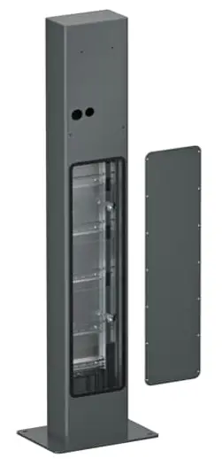
QUICK START GUIDE
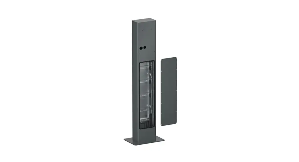
Pedestal for Terra AC wallbox
Rectangular back-to-back 6AGC082326
| Component | Component | Component | ||||||
| A | 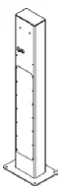 | pedestal | D x2 | 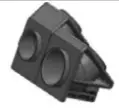 | Adapter | H x2 | 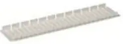 | Device cover |
| E x2 |  | Gasket 80×44 mm | I xl | 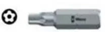 | Screw bit | |||
| B x2 |  | sleeve grommet D=35mm H=15mm | F x2 |  | Gasket D= 40 mm | 3 x4 | 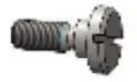 | M5x3 screw |
| C x2 |  | sleeve grommet D=30mm H=15mm | G x2 |  | Gasket D= 40 mm | K x4 | M6x80 screw with socket head | |
- 1. Remove the cover by taking out the 14 screws (use screw bit I). Next, remove the e-base cover from the e-base (1) (mounted with 4x PH2 screws).
- 2. Mount the pedestal on a concrete foundation. Use 4x anchors M10x40 for anchoring (not included in the packaging), mark 4 holes on the foundation, drill 4 holes with a diameter 12mm and minimum depth of 43mm, hammer the anchors so that they are flush with the floor, and anchor the pedestal to the foundation using 4 bolts M10 and washer.
- 3. Position the connection cables from the bottom and cut on length.
- 4. Secure the connection cables on DIN rail 1 (2). This is compatible with Phoenix Contact cable clamps: WCC 14 (3240252)/ 18 (3240253)/ 22 (3240254)/ 26 (3240255) / 30 (3240256)/ 34 (3240257) or equivalents.
- 5. Install the terminal blocks on DIN rail 2 and DIN rail components on DIN rails 3,4 and 5 each DIN rail has room for 8 slots.
- 6. Install the wiring between the terminal blocks and the DIN rail components.
- 7. Add sealings (E), (F), and (G) to adapter (D).
- 8. Remove from Terra AC the 26 and 32mm grommets and in place click in the adapter (D).
- 9. Place the 2x M5x3 screws (J) in the pedestal (A) top area and sleeve grommets (B) and (C).
- 10. Mount the Terra AC Wallbox on the pedestal (A). Take the front cover off.
- 11. Screw in the 2x M6x80 (K).
- 12. Continue installation of the Terra AC Wallbox as per the device installation manual.
- 13. Mount the e-base cover on the e-base.
- 14. Cut the device covers (H) as required per the installation conducted.
- 15. Close cover pedestal (A).
Note (1): e-base can be wired separately/outside from the pedestal(A). It can be taken out and in again including DIN rail components and wiring.
Note (2): The DIN rail component can be changed to support different terminal block models.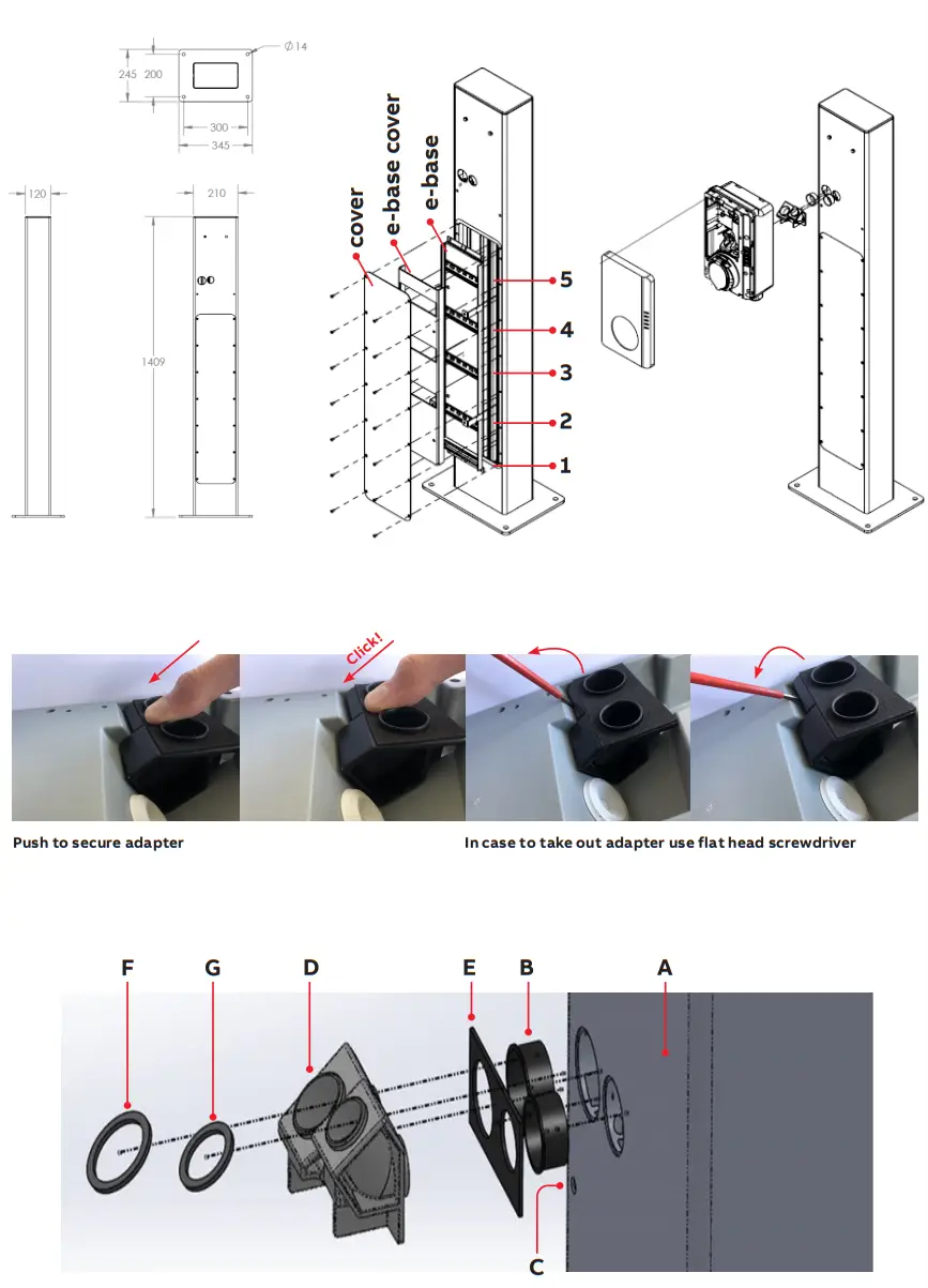
![]()


