![]() HSK 390 PRC
HSK 390 PRC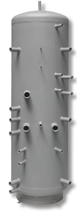 Installation and Operation Instructions
THERMAL STORE with stainless-steel DHW tube heat exchanger
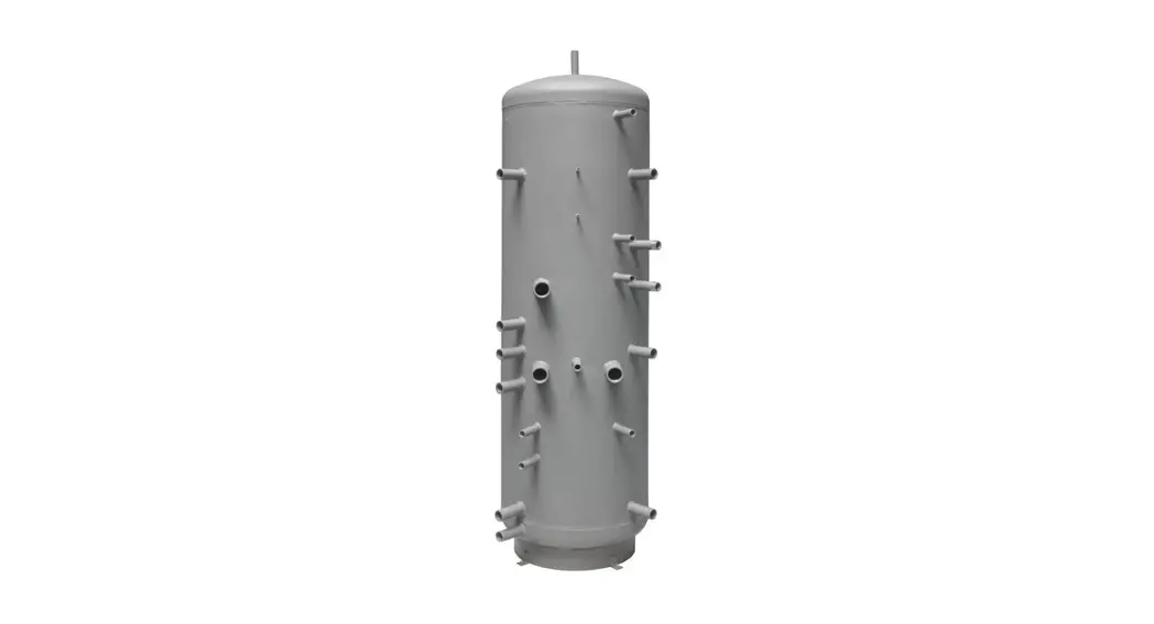
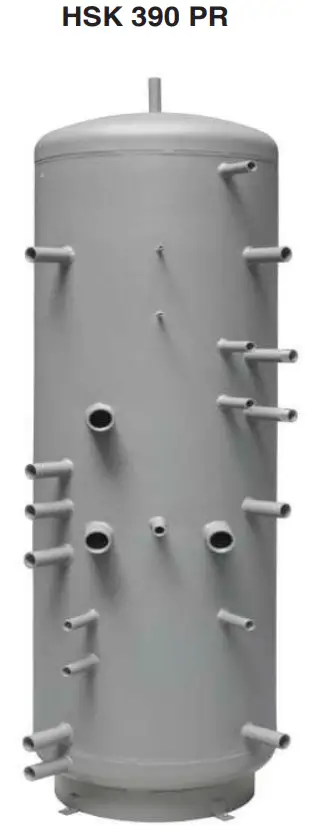
HSK 390 PR
Description
HSK PR Thermal Stores are intended for storing and subsequent distribution of thermal energy of heating water.
They are fitted with a stainless-steel tube DHW heat exchanger, permitting installation of electric heating elements and connection of other heat sources. For a better thermal layering, the tank volume is separated by a baffle. The lower section is equipped with a steel solar heat exchanger. This thermal store shall be always connected to a sealed heating circuit.
For proper operation of a tank, it is necessary to have an optimum hydraulic design of the entire heating system, i.e. position of circulation pumps for both heat sources and heating circuits, valves, check valves etc. When more heat sources shall be combined, it is recommended to use a smart controller for both the heat source and heat sink sides of a heating circuit, i.e. also for charging and discharging a thermal store.
1.1 – Models
Model of 394 l total volume with stainless-steel tube DHW heat exchanger.
1.2 – Tank protection
The thermal store has no inner surface finish, the outer surface is painted in gray. The DHW heat exchanger is made of stainless steel.
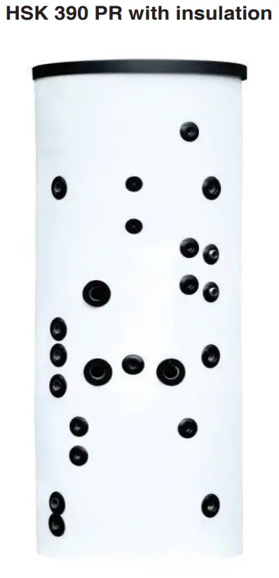
1.3 – Thermal insulation
Thermal insulation is available as a separate item. For easier handling, the insulation shall not be fitted on the tank until it reaches its definite place of installation. The insulation is made of fleece, 100 mm thick, with PUR leather surface, and closes with a zipper.
1.4 – Packaging
Thermal stores are delivered standing, each screwed to its pallet, packed in bubble wrap
It is forbidden to transport and/or store the thermal stores in a horizontal position.
General Information
This Owners Manual is an integral and important part of the product and must be handed over to the User. Read carefully the instructions in this Manual as they contain important information concerning safety, installation, operation and maintenance. Keep this Manual for later reference. The appliance shall be installed by a qualified person according to valid rules and Manufacturer‘s Instructions.
This appliance is designed to accumulate thermal energy and distribute it subsequently. It must be connected to a heating system and heat sources. This appliance is suitable for continuous heating of domestic hot water.
Using the thermal store for other purposes than above described is forbidden and the manufacturer accepts no responsibility for damage caused by improper or wrong use or filling procedure.
The appliance shall be installed by a qualified person according to valid rules, otherwise the warranty becomes null and void.
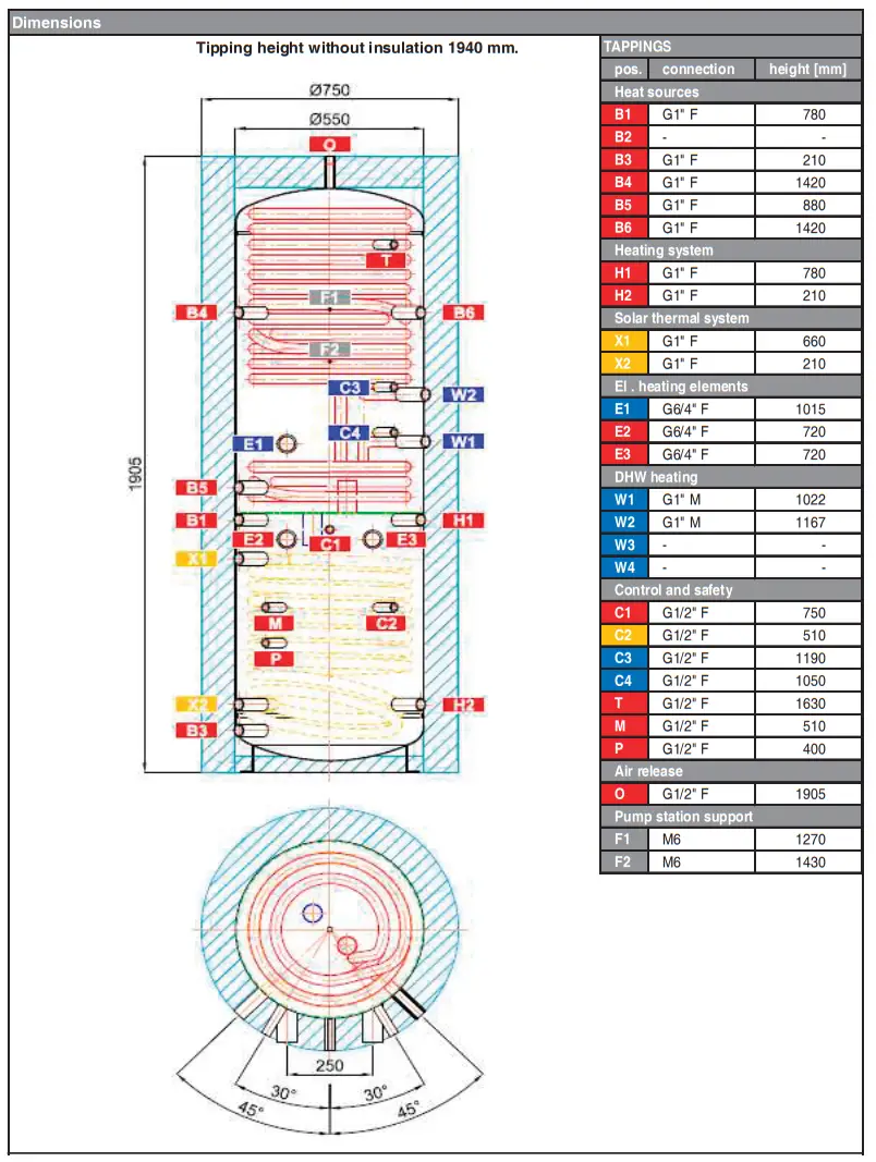
Technical Data and Dimensions of HSK 390 PR Model HSK 390 PR with insulation
| Code | |
| Thermal Store | 14 172 |
| Insulation | 16 319 |
Application
Thermal Store for storing heat and continuous DHW heating. A tight separating metal sheet increases Seasonal Performance Factor of a heat pump and efficiency of a solar thermal system. A stainless-steel DHW heat exchanger is located in the upper section (above the metal sheet), in the lower section below the metal sheet there is a solar heat exchanger.
Energy Efficiency Data (as per EC Regulation No. 813/2013)
| Energy efficiency class | HSK 390 PR with insulation C |
| Standing loss | 82 W |
| Storage volume | 385 l |
Technical Data
| Total tank volume | 394 l |
| Fluid volume in tank | 364 l |
| Solar heat exchanger volume | 9 l |
| Upper DHW heat exchanger volume | 21 l |
| Lower DHW heat exchanger volume | – |
| Solar heat exchanger surface area | 1,5 m² |
| Upper DHW heat exchanger surface area | 6 m² |
| Lower DHW heat exchanger surface area | – |
| Max. working temperature in Thermal Store Max. working temperature in solar HE | 95 °C |
| Max. working temperature in DHW heat | 95 °C |
| exchangers | 95 °C |
| Max. working pressure in Thermal Store | 4 bar |
| Max. working pressure in Thermal Store | 4 bar |
| Max. working pressure in solar HE | 10 bar |
| Max. working pressure in DHW heat | 10 bar |
Tank Materials
| Tank material | S235JR |
| Solar heat exchanger material | S235JR+N |
| DHW heat exchanger material | AISI 316 L |
Insulation Materials
| Tank perimeter insulation | fleece |
| Tank perimeter insulation outer surface | PU leather |
| Top and bottom tank insulation | fleece |
Dimensions, Tipping height, Insulation thickness, Weight
| Tank diameter | 550 mm |
| Tank diameter with insulation | 750 mm |
| Tank overall height | 1905 mm |
| Tipping height without insulation | 1940 mm |
| Tank perimeter insulation thickness | 100 mm |
| Bottom insulation thickness | 50 mm |
| Top insulation thickness | 120 mm |
| Empty weight without insulation | 110 kg |
Accessories
| El. heating element (models) | ETT-C, J, L |
| Heating elem. max. length / output | 4x 555 mm / 6 kW |
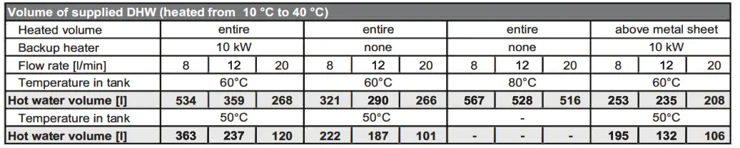
Volume of supplied DHW (heated from 10 °c to 40 °C)
Operation
This tank is designed for heating and storing heating water in household or industrial applications, however always in closed pressure circuits with forced circulation. Hot water is heated inside the thermal store from several possible heat sources like various kinds of heating boilers, renewable energy sources or also electric heating elements. A stainless–steel tube DHW heat exchanger is heated by heating water inside the thermal store. It connects through 1″ threaded fittings. When hot water is drawn from the outlet point, cold water flows into the immersed heat exchanger and heats up by the heating water. The thermal store shall be connected to heat sources through connecting threaded fittings. Individual connection points are assigned according to the circuits to be connected. There is a wide choice of combi-nations; the following chapter describes just some examples.
Typical Layout Examples with Thermal Store
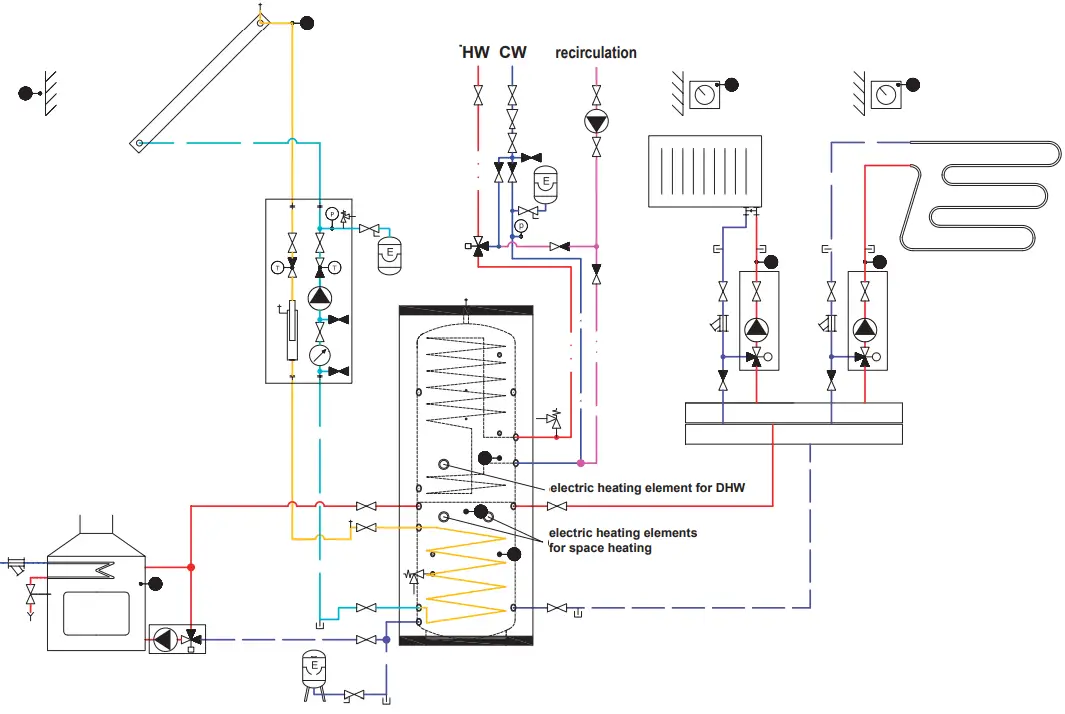
Example I.
Solar collector + el. heating element + solid-fuel boiler
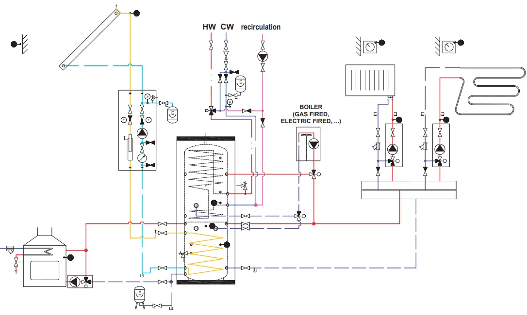
Example II.
Solar collector + gas-fired boiler+ solid-fuel boiler
Installation and Commissioning
Installation must meet valid rules and may be done only by qualified staff.
Defects caused by improper installation, use or handling are not covered by warranty.
After the tank is installed and connected to an existing heating system, it is recommended to clean the entire heating system using a suitable cleaning agent, e.g. MR-501/R.
Anti-corrosion protective liquid should be also used, e.g. MR-501/F.
6.1 – Connection to heat sources
Place the tank on the floor, as close to your heat source as possible. Connect the heating circuits to inlets and outlets respecting the thermal stratification in the tank. Install a drain valve at the lowest point of the tank.
Install an air vent valve at the highest point of the system. Insulate all the connection piping.
6.2 – Connection to a solar thermal system
The tank can be used with a solar thermal system. In such a case, the inlet for hot solar fluid coming from the solar thermal system shall be connected to the upper tapping of the G 1” heating coil and the lower outlet to the return piping to the solar thermal system. Insulate meticulously all the piping between the tank and the solar thermal system.
6.3 – Installation of an el. heating element
The G 6/4“ side tappings are designed to accommodate electric heating rods. They can be connected either directly to the mains (thermostat-equipped rods), or to a heating system controller. The installation may be done by qualified staff only.
Warning: Electric heating elements shall be protected by a safety thermostat.
6.4 – Connection to water mains
DHW piping shall be done according to valid rules. Installation of a pressure reducing valve on the immersed tank inlet is recommended. For water mains pressure above 6 bar a pressure reducing valve is necessary. To prevent water loss, we recommend installing an expansion vessel at the cold water inlet with a minimum volume of 4% of the total volume of water in the DHW piping, including heat exchangers, circulation pipes, etc. (usually 8 l). Should the water be too hard, install a water softener before the tank. In case the water contains mechanical impurities, install a strainer.
Table of limit values for total dissolved solids in hot water.
| Description | pH | Total dissolved solids (TDS) | Ca | Chlorides | Mg | Na | Fe |
| Max. value | 6,5 – 9,5 | 600 mg/l | 40 mg/l | 100 mg/l | 20 mg/l | 200 mg/l | 0,2 mg/l |
6.5 – Commissioning
Ground the tank before commissioning.
The tank shall be filled up together with the heating system, respecting valid standards and rules. In order to minimize corrosion, special additives for heating systems should be used. The quality of heating water depends on the quality of filling water at commissioning, on the top-up water and on the frequency of topping up. This has a strong influence on the lifetime of heating systems. Poor quality of heating water may cause problems like corrosion or incrustation, esp. on heat transfer surfaces.
Quality of DHW shall meet the conditions shown in the Table of limit values for total dissolved solids in hot water on this page. Fill the heating circuits with the appropriate fluids and air-bleed the entire system. Check all connections for leaks and verify the system pressure. Set the heating controller in compliance with the documentation and manufacturer’s recommendations. Check regularly the proper function of all control and adjustment elements.
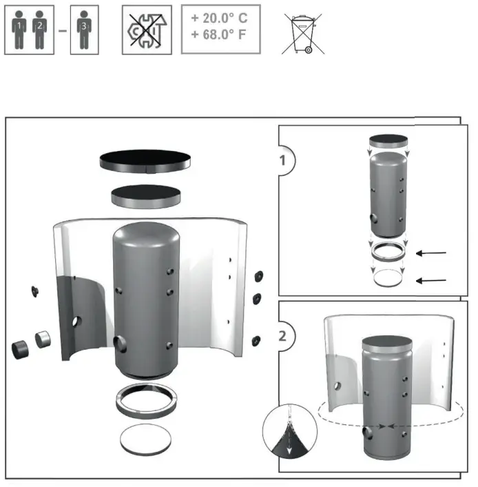
Installing Insulation on the Tank
Product description
Thermal insulation is a part of thermal stores, preventing heat loss. For easier handling, the insulation shall not be fitted on the tank until it reaches its definite place of installation. The insulation is made of fleece with a PUR leather surface and zipper.
Warning
Insulation installation shall be done in two or three persons, depending on its size. The zippered, PVC coated fleece insulation must not be installed at temperatures below 20 °C. If this cannot be avoided, the insulation shall be prewarmed in another room to at least 20 °C. It is impossible to install insulation of lower temperature, there is a risk of damage, esp. to the zipper.
Do not use any tools for installation.
Keep away from open fire.
Installing Insulation
- Fix the tank following installation instructions.
- Wrap the insulation around the tank carefully. Check that the insulation adheres to its body perfectly. This can be reached by rubbing and patting the insulation by hand from its center evenly in both directions until the insulation adheres to the tank’s surface completely and no bubbles are left.
- Use the holes for tappings as a rest during the insulation installation.
- At least one person presses the insulation to the tank, pulling both ends together. The other person closes the zipper.
- Put on the upper insulation and cover
- Push on the covering plastic rosettes depending on the size of tappings, or put on the flange plug(s) with insulation.
- Finish the tank installation in compliance with the respective instructions and valid standards and rules.
Warranty on insulation
- Warranty shall become null and void if:
○ the procedure described in the Installation Manual was not respected,
○ the product was used for other purposes than intended. - Warranty does not cover:
○ usual wear and tear,
○ damage caused by fire, water, electricity or a natural disaster,
○ defects caused by failure to use the product in compliance with its intended purpose, by improper use and insufficient maintenance,
○ defects caused by mechanical damage to the product,
○ defects caused by tampering or incompetent repair.
Maintenance
If the tank is fitted with a heating element, disconnect it from the mains first. Clean the exterior of the tank with a soft cloth and a mild detergent. Never use abrasive cleaners or solvents.
Check all connections for leaks.
Disposal
Packaging shall be disposed of in compliance with the valid rules. When the product reaches the end of its life, it shall not be disposed of as household waste. It shall be dropped off at a Local Waste Recycling Center.
Insulation shall be recycled as plastic and the steel vessel as scrap iron.
Warranty
This product is covered by warranty under conditions specified in this Manual and the respective Warranty Certificate.
The Warranty Certificate is an integral part of supply of this Thermal Store.
©2023 We reserve the right to errors, changes and improvements without prior notice.
v1.3-01/2023
REGULUS spol. s r.o.
E-mail: [email protected]
Web: www.regulus.eu


