eSID9-5 Small Electronic Device Instruction Manual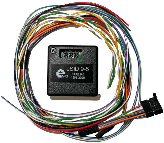
Change Log
| 2022-11-30Version 1.0 | Initial Version |
| 2023-01-03Version 1.1 | Highlighted I-Bus cable colors differences compared to eSID for 9-5 2006-2010. I-Bus cable colors are mixed up on 2006-2010 compared to previous years. Added eSID Cable colors column to every different car generation, for clarification. |
Introduction
The eSID9-5 (here referred to as “eSID”) is a tool that can be integrated into a Saab OG9-5 vehicle from 1998-2010 and Saab OG9-3 1998-2003 and enhances the Saab driving experience by collecting internal hidden car data and present it to the driver on the built-in SID (Saab Information Display. These vehicles are equipped with two CAN-communication buses (P-Bus, and I Bus) and the eSID needs access to both these buses for full functionality. On older Saab 9-3 with Trionic5 EMS (All cars MY1998-2000, except Viggen) there is only I-Bus, so P-Bus shall not be connected.
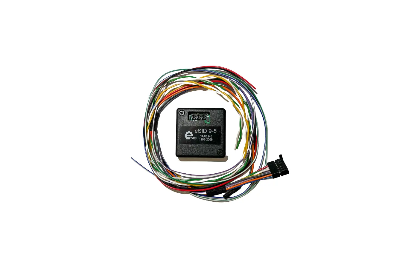
A cable kit is included with the unit and needs to be installed in the vehicle before use. From the Instrument cluster connector, it is possible to find Battery, Ground, Ignition and the two CAN-buses, and from the Turn Indicator Stalk connector the Left/Right Indicator cables (For the 3-Blink function, optional)
eSID Pinout
The eSID connector pinout is according table below and cable color is according to the cable kit.
| Pin | Function | Cable color | Mandatory | Comment |
| 1 | Power Ground | BK | Yes | |
| 2 | P-Bus_H | GN | Yes | Bus cables needs to be twisted |
| 3 | I-Bus_H | YE | Yes | Bus cables needs to be twisted |
| 4 | TurnIndicator_Left | BL/WH | No | Only needed for 3-Blink function |
| 5 | TurnIndicator_Right | GN/WH | No | Only needed for 3-Blink function |
| 6 | K-Line | BU | No | Reserved for future use |
| 7 | Battery (+30) | RD | Yes | |
| 8 | P-Bus_L | WH | Yes | Bus cables needs to be twisted |
| 9 | I-Bus_L | WH | Yes | Bus cables needs to be twisted |
| 10 | Ignition (+15) | VT/WH | Yes | |
| 11 | 12V_DigitalOutput | GY | No | Only needed if the optional digitaloutput is used |
| 12 | GND_ Digital Output | OG | No | Only needed if the optional digital output is used |
Important Note! Check the later sections to see which the corresponding cable colors are in your vehicle. For instance, I-Bus cable colors on 2006-2010 are mixed up compared to previous years.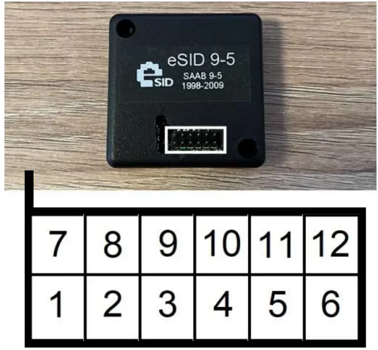
Color Table
| Color | Color Code | Color Name |
| BN | Brown | |
| BK | Black | |
| BU | Blue | |
| GN | Green | |
| GY | Gray | |
| OG | Orange | |
| RD | Red | |
| VT | Violet | |
| WH | White | |
| YE | Yellow |
Connecting the cable kit
The cable kit cables need to be spliced together with the corresponding cables in the vehicle. seven cables on the instrument cluster connector and two on turn indicator stalk connector (optional). In order to access these parts, the dashboard needs to be removed. The eSID9-5 will be placed behind the fuse cover on the near the light switch for easy access on the 9-5.
On the OG9-3 there is unfortunately no space near the fuses, and it is suggested that its placed near the hood opening switch, behind the floor panels. It is recommended to have easy access to it and disconnect it when using TECH2.
Saab 9-5 (Left), Saab 9-3 (Right)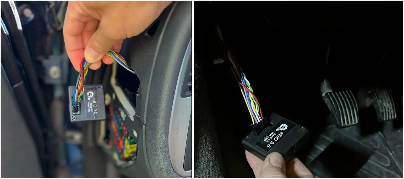
Removing Dashboard on Saab 9-3 MY98-MY03
Step1: Left Side Items
Pull the Main Light Switch out, and the push the 5 switches (or blanks) out from behind.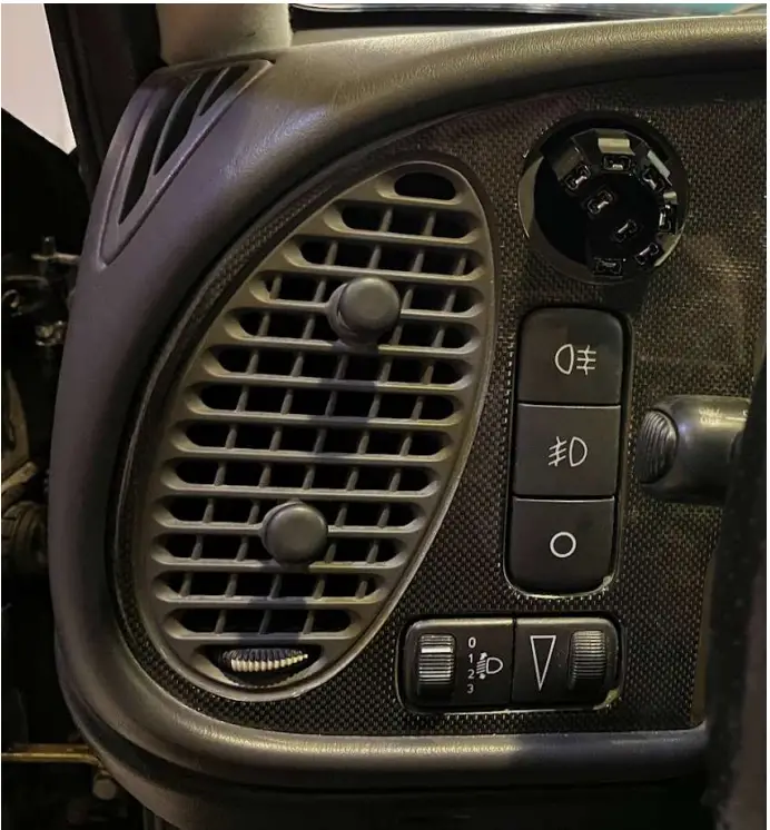
Step2: Radio
Start with the radio, take it out using the special tools and pull it straight out.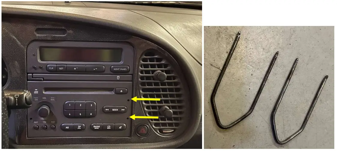
Step3: SID and Radio frame
Push the SID out from behind, and then take out the Radio mounting frame by lifting in slightly while pushing in forward at the same time (its snapped on the dashboard in the front)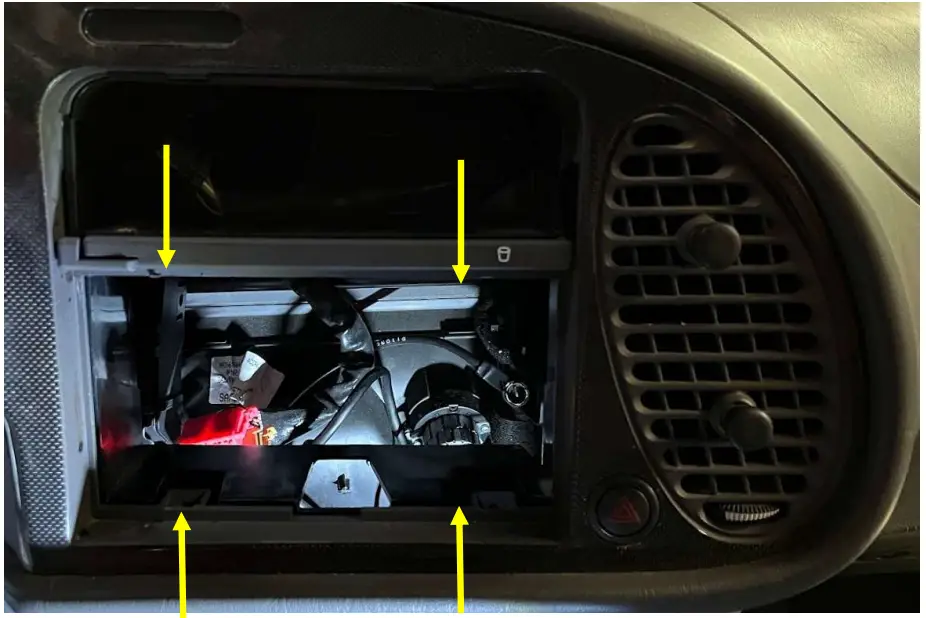
Step4: Remove steering column cover
Turn the steering wheel left/right to reveal the two front screws and the third one is directly under. After removing the screws, take the off the top cover first, and be careful on the small plastic pieces on the lower part near the screw holes. Remove the stalks from the steering column and let them be hanging.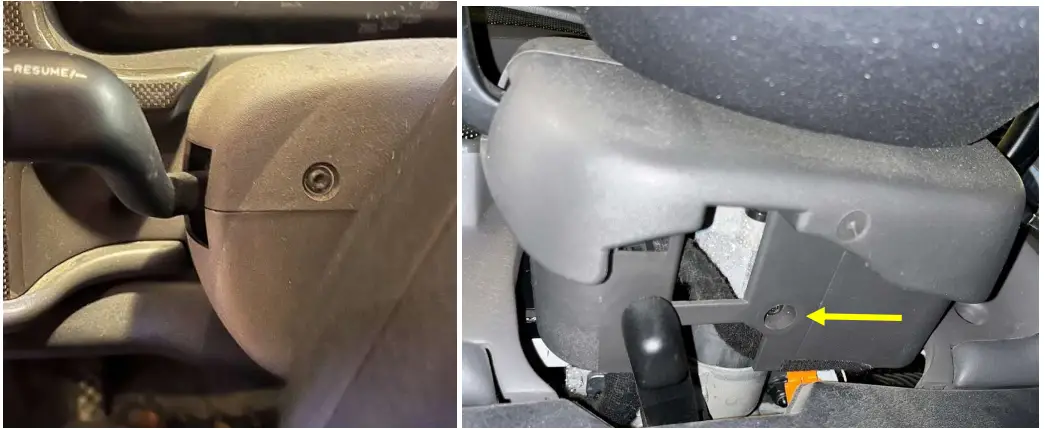
Step5: Remove the Dashboard
Remove the 9 screws and take out the dashboard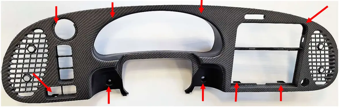
Step6: Remove the Instrument Cluster
Remove the 4 screws and pull it out. Remove the connector.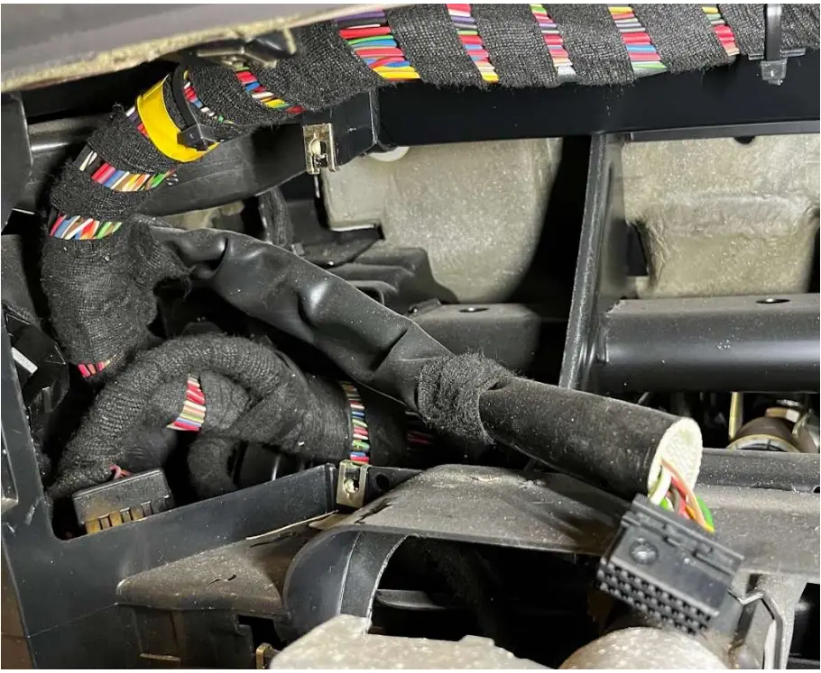
Step7: Connect the eSID cables into the vehicle harness
Look at the cable colors and location of the cables in the eSID9-5 Cable kit (included). Locate the corresponding cable in the vehicle harness by using the Pinout sections below. Seven cables to the instrument cluster (five cables if car has Trionic5) and two cables to the turn indicator stalk. When ready, the eSID9-5 connector should be accessible near the pedals.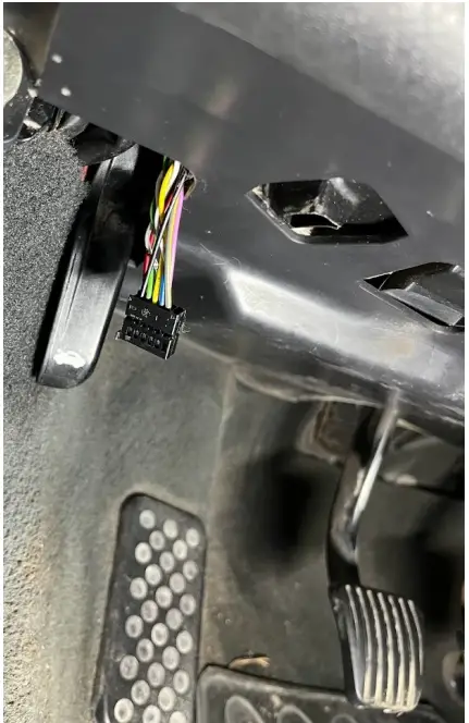
Removing Dashboard on Saab 9-5 MY98-MY05
Step1: Radio/Navigation:
Use the special radio tools to remove the Radio. For Navigation see MY06 chapter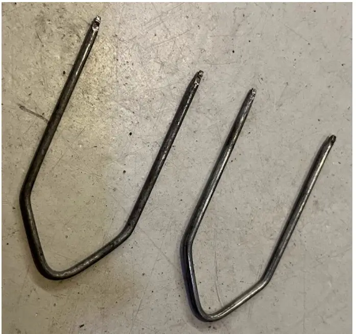
Step2-6:
Same as for MY06, See below.
Removing Dashboard on Saab 9-5 MY06-MY10
Step1: Radio:
If car is equipped with radio, start by removing the four front covers using double sticking tape, then the screws. Then continue by pushing out the ACC panel from behind.
Step1: Navigation:
If car is equipped with navigation (and you don’t have the special tools), then a tip is to start with the plastic decor with the cigarette lighter (#1.1), then push the ACC panel (#1.2) from behind. And finally push the navigation panel from behind while using four old ice cream sticks in the holes (#1.3). The navigation mounting frame also needs to be removed from the dashboard.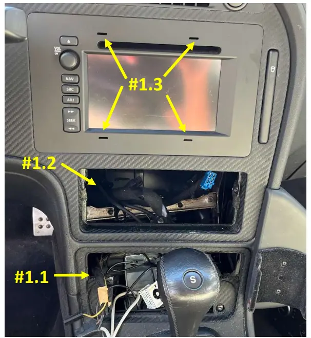
Step2: Switches
Remove the light switch and other switches by pushing them out from the back after removing the fuse cover.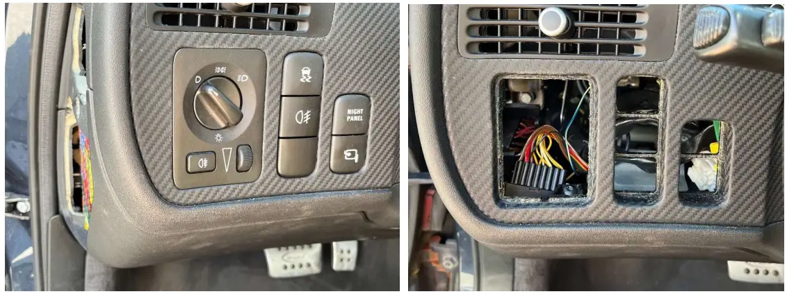
Step3: Remove steering column cover
Turn the steering wheel left/right to reveal the two front screws and the third one is directly under. After removing the screws, take the off the top cover first, and be careful on the small plastic pieces on the lower part near the screw holes. Remove the stalks from the steering column and let them be hanging.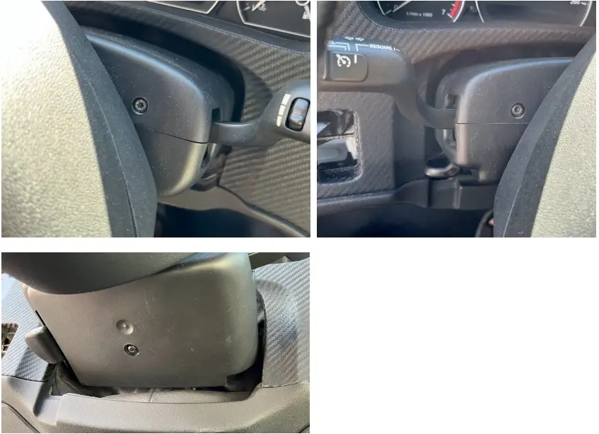
Step4: Remove Dashboard
Remove the 6 dashboard screws, put the gear lever in L (if Automatic) and pull out the dashboard.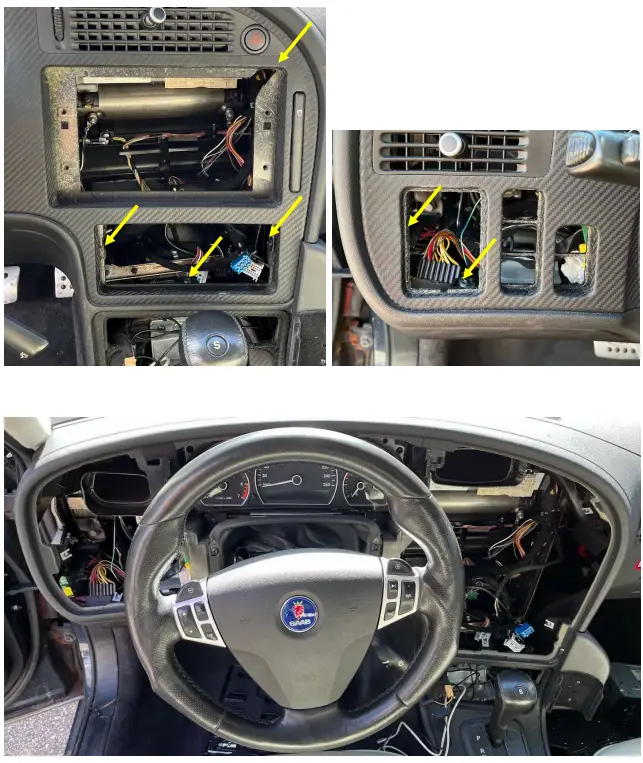
Step5: Remove the instrument cluster
First remove the cover between the instrument cluster and the steering wheel (two screws, red arrows), then Remove the four screws (yellow arrows) and take out the instrument cluster. The pinout and connectors behind the cluster depends on the year of the vehicle. See next chapters for details where to splice the eSID cables.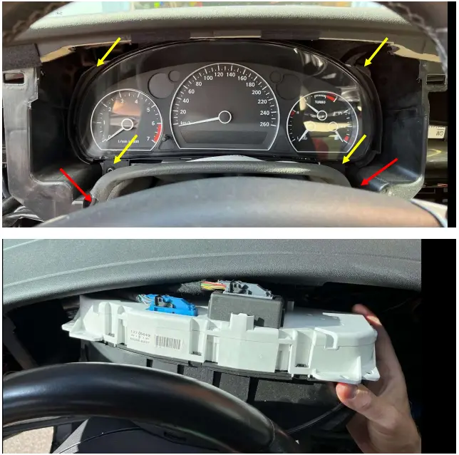
Step6: Connect the eSID cables into the vehicle harness
Look at the cable colors and location of the cables in the eSID9-5 Cable kit (included). Locate the corresponding cable in the vehicle harness by using the Pinout sections below. Seven cables to the instrument cluster and two cables to the turn indicator stalk. When ready, the eSID9-5 connector should be accessible from the fuse cover near the light switch.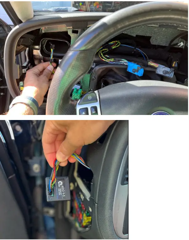
Pinout: Instrument Cluster 9-3 T5 1998-2000
This variant has three connectors, K12 (12 pin), K20 (20 pin) and K22 (22 pin). Use only K12.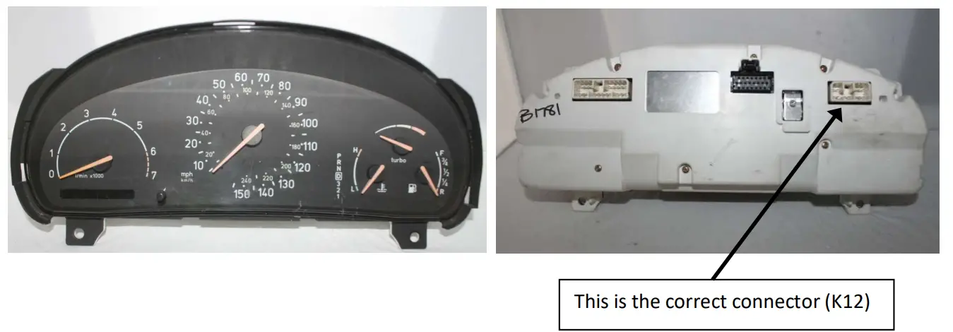
| MIU Pin K12 | Function | M IUCable color | eSID Cable color |
| 7 | Battery (+30) | RD | RD |
| 1, 6 | Ignition (+15) | YE/GY | VT/WH |
| 2, 3 | Power Ground | BK | BK |
| 5 | I-Bus_ H | GN | YE |
| 12 | I-Bus_ L | WH | WH |
Note1: Ignition and Power Ground has multiple pins, use only one!
Note2: This variant does not have a P-BUS (leave those cables unconnected).
Note3: It is also possible to splice in the five cables from the Radio or the SID connector. (since no P-Bus).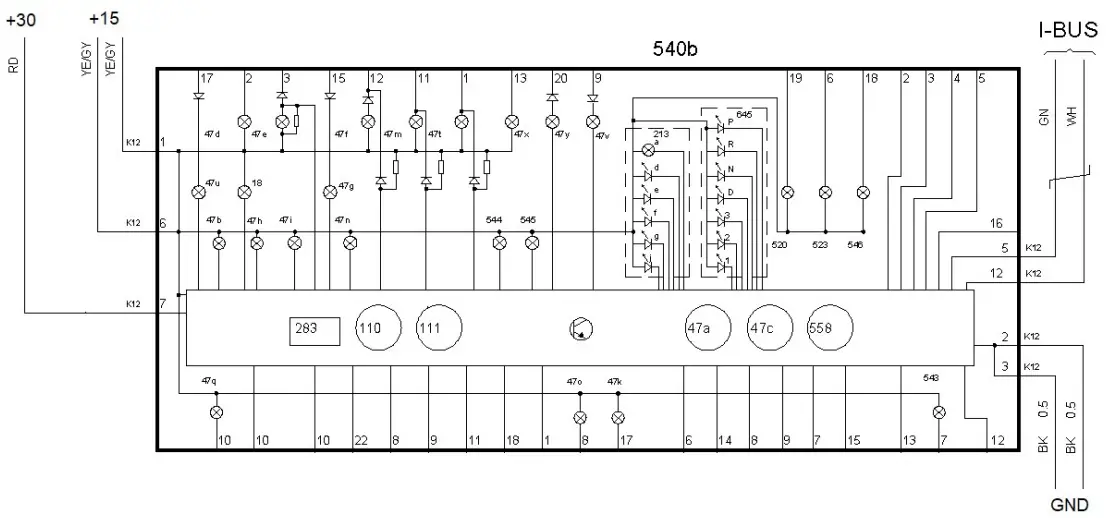
Pinot: Instrument Cluster 9-5 1998-2001 + 9-3 T7 1999-2001
This model has two connectors, K12 (12 pin), and K20 (20 pin). Use only K12.
| MIUPinK12 | Saab 9-5 Function | MIUCablecolor | eSIDCablecolor |
| 7 | Battery (+30) | RD | RD |
| 1, 6 | Ignition (+15) | RD/BU | VT/WH |
| 2, 3 | Power Ground | BK | BK |
| 5 | I-Bus_H | GN | YE |
| 12 | I-Bus_L | WH | WH |
| 4 | P-Bus_H | GN | GN |
| 11 | P-Bus_L | WH | WH |
MIU PinK12 | Saab 9-3 T7 Function | MIUCablecolor | eSIDCablecolor |
| 7 | Battery (+30) | RD | RD |
| 1, 6 | Ignition (+15) | YE/GY | VT/WH |
| 2, 3 | Power Ground | BK | BK |
| 5 | I-Bus_H | GN | YE |
| 12 | I-Bus_L | WH | WH |
| 4 | P-Bus_H | GN | GN |
| 11 | P-Bus_L | WH | WH |
Note! Ignition and Power Ground has multiple pins, use only one!
Pinout: Instrument Cluster 9-5 2002-2005 + 9-3 2002-2003
This model uses a single connector (22 pin).
| MIUPin | Saab 9-5 Function | MIUCable color | eSIDCable Color |
| 1 | Battery (+30) | RD | RD |
| 2 | Ignition (+15) | RD/BU | VT/WH |
| 18 | Power Ground | BK | BK |
| 8 | I-Bus_H | GN | YE |
| 16 | I-Bus_L | WH | WH |
| 17 | P-Bus_H | GN | GN |
| 9 | P-Bus_L | WH | WH |
| MIUPin | Saab 9-3 Function | MIUCable color | eSIDCable Color |
| 1 | Battery (+30) | RD | RD |
| 2 | Ignition (+15) | YE/GY | VT/WH |
| 18 | Power Ground | BK | BK |
| 8 | I-Bus_H | GN | YE |
| 16 | I-Bus_L | WH | WH |
| 17 | P-Bus_H | GN | GN |
| 9 | P-Bus_L | WH | WH |
Pinout: Instrument Cluster 9-5 2006-2010
This model uses a single connector (32 pin). See a video here how to disassemble the connector (to see pin vs cable colors):
(same principle): https://youtu.be/83eY2UN0x9U
| MIUPin | Function | MIUCable color | eSIDCable color |
| 1 | Battery (+30) | RD/WH | RD |
| 3 | Power Ground | BK/WH | BK |
| 17 | Ignition (+15) | VT/BN | VT/WH |
| 18 | I-Bus_L | GN | WH |
| 19 | I-Bus_H | WH | YE |
| 20 | P-Bus_L | WH | WH |
| 21 | P-Bus_H | GN | GN |
Note! The cable color in the cars are not the same as WIS ! Both bus-cables are WH/GN BUT on I-bus CAN_L is Green and on P-bus CAN_H is Green.
Also note that I-Bus cable color differences between MIU and eSID.
Be very careful and look at the Pin number, which is correct.
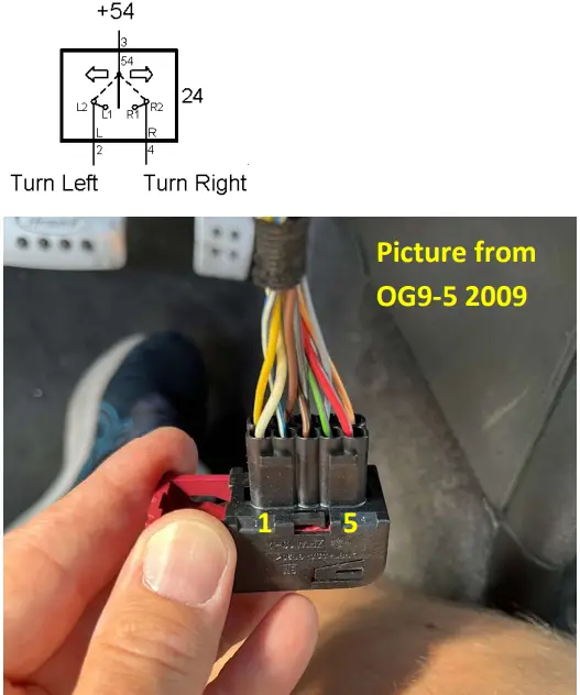
Pinout: Turn Indication Stalk Connector
From the Turn Indication Stalk two cables needs to be connected to eSID.
| Pin | Function | OG9-5Cable color MY98-05 | OG9-5Cable color MY06-10 | OG9-3Cable color MY99-00 | OG9-3Cable color MY01-03 |
| 2 | Turn Indicator Left | WH | WH/BU | BN/OG | OG/BN |
| 4 | Turn Indicator Right | YE | GN/VT | GY/OG | OG/GY |