EXOR ESMART04 Graphical Workstations
Introduction
The operational guidelines describe below is information on device technical data, installation, transportation, storage, assembly, use and maintenance.
The Manual refers to the following models:
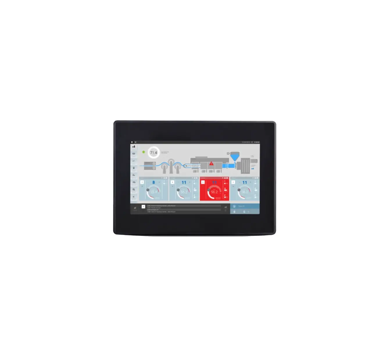
eSMART04: Operator interface with TFT color 4.3” widescreen display touchscreen.
eSMART04M: High performance operator interface with TFT color 4.3” widescreen display touchscreen.
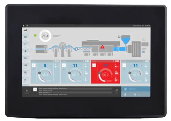
eSMART07: Operator interface with TFT color 7” widescreen display touchscreen.
eSMART07M: High performance operator interface with TFT color 7” widescreen display touchscreen.
eSMART10: Operator interface with TFT color 10.1” widescreen display touchscreen.
Safety Guide
The manual contains safety standards that must be respected for the personal safety and to avoid damage. Indications of attention are divided into three levels of severity:
 DANGER
DANGER: indicates a failure to observe safety rules and such failure may cause death or serious injuries.
 ATTENTION
ATTENTION: indicates a failure to observe safety rules and that deficiency may cause damage.
![]() CAUTION
CAUTION
CAUTION: indicates a failure to observe safety rules and that deficiency may cause defects to the equipment or inconsistencies.
Product Overview
The EXOR eSMART HMI products combine state-of-the-art features and top performance with an outstanding design. They have been designed to offer an outstanding price/performance ratio for challenging applications. They are the ideal choice for HMI applications including factory and building automation.
The eSMART HMI products have been designed to run the JMobile software.
- Compatible with JMobileStudio.
- Full vector graphic support. Native support of SVG graphic objects, trasparency and alpha blending.
- Screen object dynamics: control visibility and transparency, move, resize, rotate any object on screen. Change properties of basic and complex objects.
- Multilanguage applications with TrueType fonts. Easily create, install and maintain applications in multiple languages to meet global requirements.
- Data display in numerical, text, bargraph, analog gauges and graphic image formats.
- Rich set of state-of-the-art HMI features: data acquisition and logging, trend presentation, alarm handling, scheduler and timed actions (daily and weekly schedulers, exception dates), recipes, security and user management, email and RSS feeds.
- Wide selection of communication drivers available with multiple-driver communication capability.
- Remote monitoring and control with Client-Server functionality.
- On-line and Off-line simulation with JMobile Studio.
- Powerful scripting language for automating HMI applications. Efficient script debugger improves productivity in application development.
- Rich gallery of vector symbols and objects.
Standards and Approvals
The products have been designed for use in an industrial environment in compliance with the 2014/30/EU EMC Directive.
The products have been designed in compliance with:
| EN 61000-6-4 EN 61000-6-3 | EN 55011 Class A EN 55022 Class B |
| EN 61000-6-2 EN 61000-6-1 | EN 61000-4-2 EN 61000-4-3 EN 61000-4-4 EN 61000-4-5 EN 61000-4-6 EN 61000-4-8 |
| EN 60079-0 EN 60079-7 EN 60079-11 | |
| ATEX EN 60079-0: 2012+A11:2013 EN 60079-7: 2015 EN 60079-11: 2012 | DEMKO 16 ATEX 1761X II 3G Ex ic ec IIC T6 Gc 0≤Tamb≤+50°C |
The installation of these devices into the residential, commercial and light-industrial environments is allowed only in the case that special in measures are taken in order to ensure conformity to EN 61000 6-3.
The products are in compliance with the Restrictions on Certain Hazardous Substances (RoHS) Directive 2011/65/EU
In compliance with the above regulations the products are CE marked.
Special instruction for use
- The equipment shall only be used in an area of not more than pollution degree 2, as defined in IEC/EN 60664-1.
- The equipment shall be installed in an enclosure that provides a degree of protection not less than IP 54 in accordance with IEC/EN 60079-7.
- Transient protection shall be provided that is set at a level not exceeding 140 % of the peak rated voltage value at the supply terminals to the equipment.
Product Identification
The product may be identified through a plate attached to the rear cover. You will have to know the type of unit you are using for correct usage of the information contained in the guide.
An example of this plate is shown in the figure below:
Note: the eSMART04 label is used as an example for eSMART Series
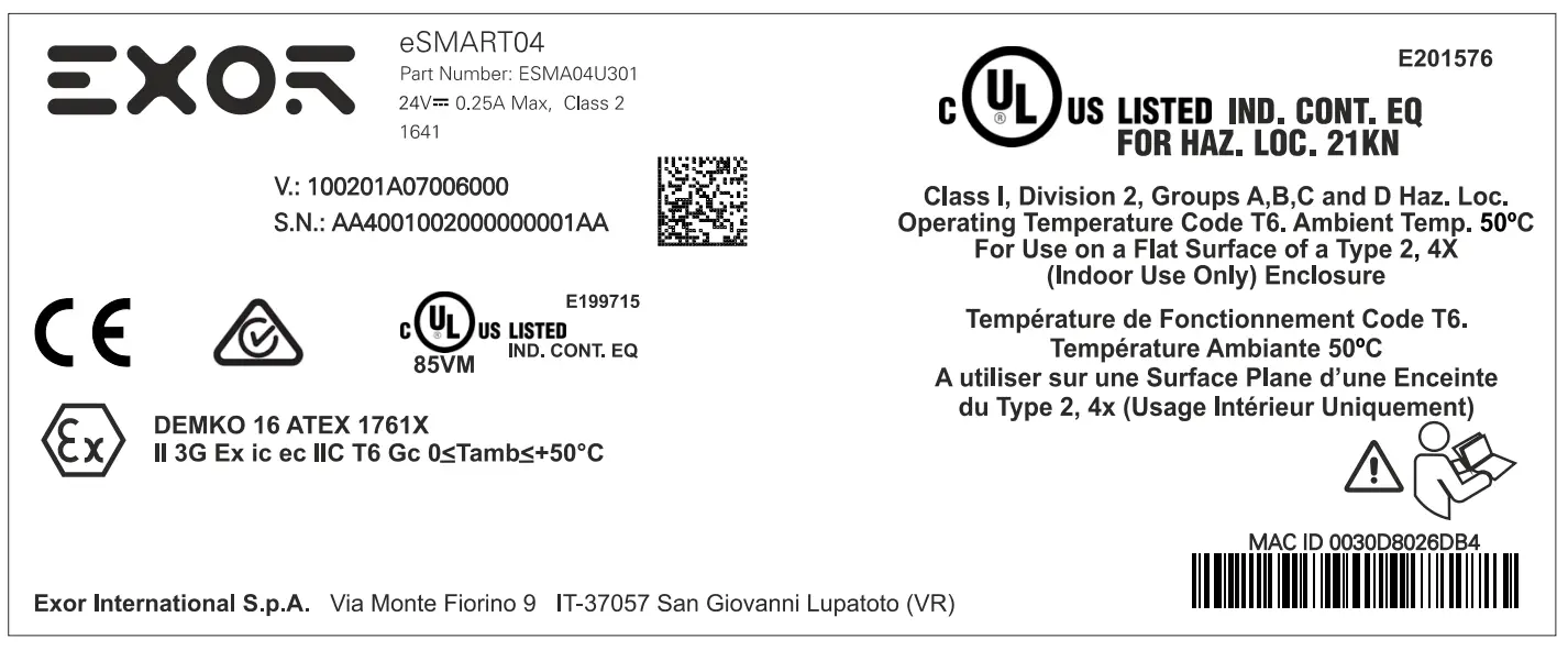
| Product model name | eSMART04 |
| Product part number | ESMA04U301 |
| Year/week of production | 1641 |
| Serial number | AA4001002000000001AA |
| Version id of the product | 100201A07006000 |
| Manufacturer address and read instruction warning | Exor International S.p.A. Via Monte Fiorino 9 IT-37057 San Giovanni Lupatoto (VR) |
| ATEX Marking | DEMKO 16 ATEX 1761X II 3G Ex ic ec IIC T6 Gc 0≤Tamb≤+50°C |
Technical Specifications
| Touchscreen technology | Resistive |
| RTC backup | Supercapacitor |
| Fuse | Automatic |
| Serial Port | RS-232, RS-485, RS-422 software configurable |
| Recipe memory | Flash |
| Hardware clock | Clock/Calendar with supercapacitor back-up |
| Accuracy RTC (at 25°C) | <100ppm |
Environmental conditions
| Operating temperature (surrounding air temperature) | 0 ÷ +50°C | EN 60068-2-14 |
| Storage temperature | -20 ÷ +70°C | EN 60068-2-14 |
| Operating and storage humidity | 5 ÷ 85 % RH not-condensing | EN 60068-2-30 |
| Vibrations | 5 ÷ 9 Hz, 7 mm p-p 9 ÷ 150 Hz, 1 g | EN 60068-2-6 |
| Shock | ± 50 g, 11 ms, 3 pulses per axis | EN 60068-2-27 |
| Protection class | IP66 front panel * | EN60529 |
| Pollution degree environment | 2 |
* The front face of the EXOR unit, installed in a solid panel, has been tested using conditions equivalent to the standards shown in the “Environmental conditions”. Even though the level of resistance EXOR unit is equivalent to these standards, oils that should have no effect on the eSMART can possibly harm the unit. This can occur in areas where either vaporized oils are present, or where low viscosity cutting oil are allowed to adhere to the unit for long periods of time. If the front face protection sheet on the eSMART becomes peeled off, these conditions can lead to the ingress of oil into the unit and separate protection measures are suggested. If the installation gasket is used for a long period of time, or if the unit and its gasket are removed from the panel, the original level of the protection cannot be guaranteed.
Electromagnetic Compatibility (EMC)
| Radiated disturbance test | Class A | EN 55011 |
| Electrostatic discharge immunity test | 8 kV (air electrostatic discharge) 4 kV (contact electrostatic discharge) | EN 61000-4-2 |
| Radiated, radio-frequency electromagnetic field immunity test | 80 MHz ÷ 1 GHz, 10V/m 1,4 GHz ÷ 2 GHz, 3 V/m 2 GHz ÷ 2.7 GHz, 1 V/m | EN 61000-4-3 |
| Burst immunity test | ± 2 KV dc power port | EN 61000-4-4 |
| Surge immunity test | ± 0,5 KV dc power port (line to earth) ± 0,5 KV dc power port (line to line) ± 1 KV signal line (line to earth) | EN 61000-4-5 |
| Immunity to conducted disturbances inducted by radiofrequency field | 0.15 ÷ 80 MHz, 10V | EN 61000-4-6 |
| Voltage dips, short interruptions and voltage variations immunity test | Port: AC mains; Level: 100% duration: 1 cycle and 250 cycles (50Hz); 40% duration: 10 cycles (50Hz); 70% duration: 25 cycles (50Hz); Phase: 0°-180 | |
| Test executed on the 230Vac | EN 61000-4-11 |
Durability information
| Backlight service life (LED type) | 20000 Hrs. or more (Time of continuous operation until the brightness of the backlight reaches 50% of the rated value when the surrounding air temperature is 25°C) – see Note 1 |
| Front foil (without direct exposure to sunlight or UV) | 10 years if the surrounding air temperature is 25°C |
| UV Resistance | Indoor applications: After 300 hours cycled humidity in QUV accelerated weathering, some yellowing and brittleness may be present. |
Solvent resistance
Contact for 1/2 hour at 21°C, No visible effect: Acetone, Butyl Cellosolve, Cyclohexanone, Ethyl Acetate, Hexane, Isopropyl Alcohol, MEK, Methylene Chloride, Toluene, Xylene Contact for 24 hours at 49°C, No visible effect: Coffee, Ketchup, Lemon Juice, Mustard (slight yellow stain), Tea, Tomato juice.
Touchscreen reliability: > 1 milion operations
Note 1: Extended use in environments where the surrounding air temperature is 40°C or higher may degrade backlight quality/reliability/durability.
| Model | eSMART04 | eSMART04M |
| Display / Backlight | TFT Color / LED | TFT Color / LED |
| Colors | 64K | 64K |
| Resolution | 480X272 | 480X272 |
| Diagonal (inches) | 4.3” widescreen | 4.3” widescreen |
| Dimming | yes | yes |
| User memory | 60 MB Flash | 60 MB Flash |
| RAM | 256 MB DDR | 512 MB DDR |
| Serial Port | RS-232,RS-485, RS-422 software configurable | RS-232,RS-485, RS-422 DB9 female software configurable |
| Ethernet port | 10/100 Mbit | 10/100 Mbit |
| USB port | Host interface V2.0 max. 500mA | Host interface V2.0 max. 500mA |
| Real Time Clock | yes | yes |
| Voltage | 24Vdc | 24Vdc |
| Current rating (at 24VDC) | 0.25A | 0.25A |
| Weight | 0.4 Kg | 0.4 Kg |
| Model | eSMART07 | eSMART07M | eSMART10 |
| Display / Backlight | TFT Color / LED | TFT Color / LED | TFT Color / LED |
| Colors | 64K | 64K | 64K |
| Resolution | 800X480 | 800X480 | 1024X600 |
| Diagonal (inches) | 7” widescreen | 7” widescreen | 10.1” widescreen |
| Dimming | yes | yes | yes |
| User memory | 60 MB Flash | 60 MB Flash | 60 MB Flash |
| RAM | 256 MB DDR | 512 MB DDR | 512 MB DDR |
| Serial Port | RS-232,RS-485, RS 422 software configurable | RS-232,RS-485, RS-422 DB9 female software configurable | RS-232,RS-485, RS-422 software configurable |
| Ethernet port | 10/100 Mbit | 10/100 Mbit | 10/100 Mbit |
| USB port | Host interface V2.0 max. 500mA | Host interface V2.0 max. 500mA | Host interface V2.0 max. 500mA |
| Real Time Clock | yes | yes | yes |
| Voltage | 24Vdc | 24Vdc | 24Vdc |
| Current rating (at 24VDC) | 0.30A | 0.30A | 0.38A |
| Weight | 0.6 Kg | 0.6 Kg | 1 Kg |
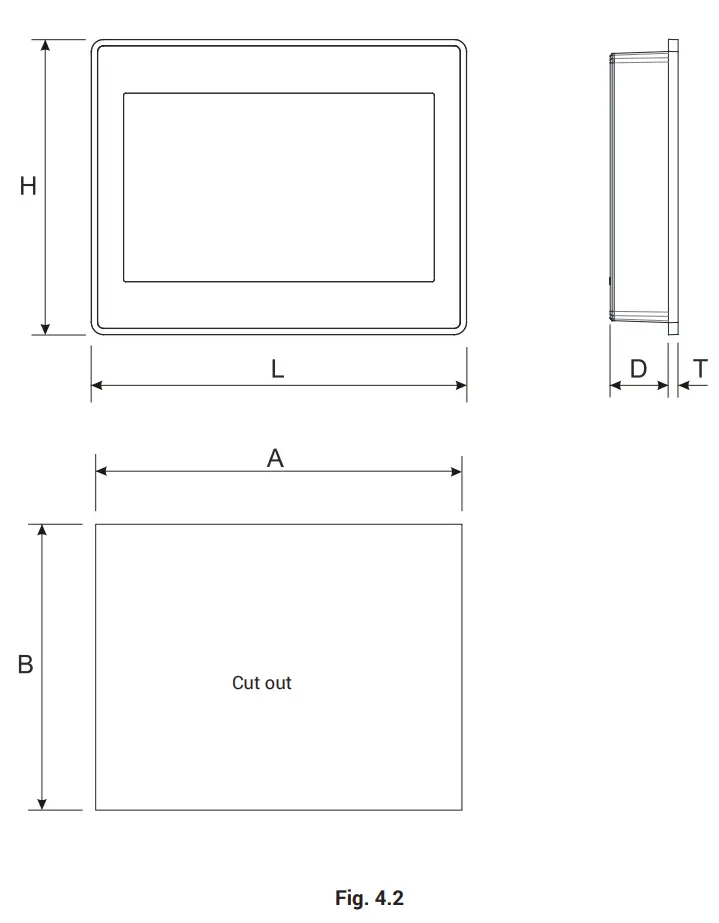
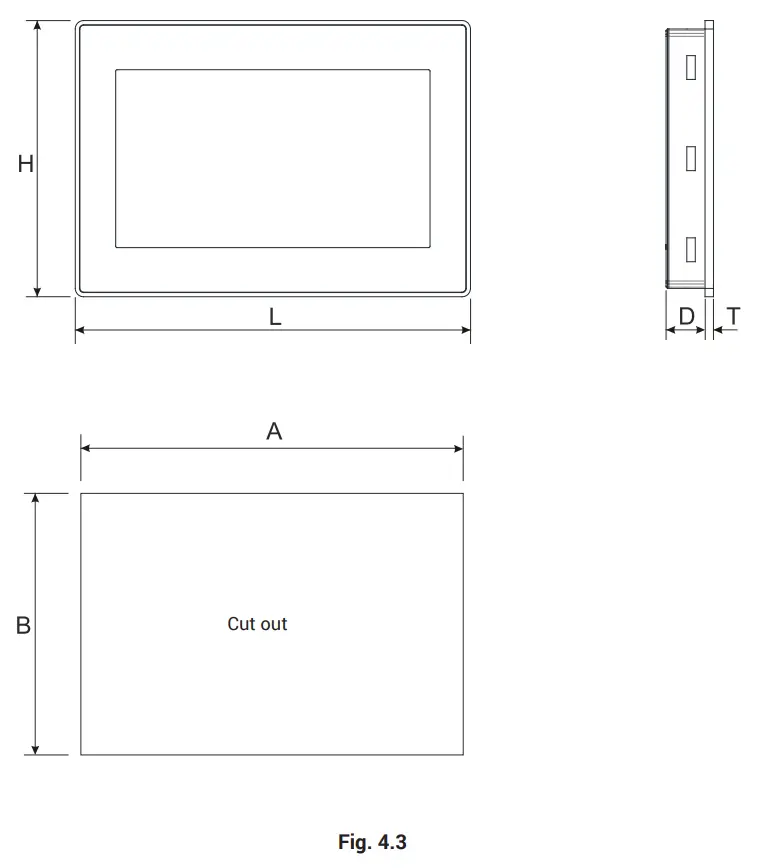
Dimensions
| MODEL | A | B | L | H | D | T |
| eSMART04 | 136mm/5.35” | 96mm/3.78” | 147mm/5.78” | 107mm/4.21” | 29mm/1.14” | 5mm/0.19” |
| eSMART04M | 136mm/5.35” | 96mm/3.78” | 147mm/5.78” | 107mm/4.21” | 29mm/1.14” | 5mm/0.19” |
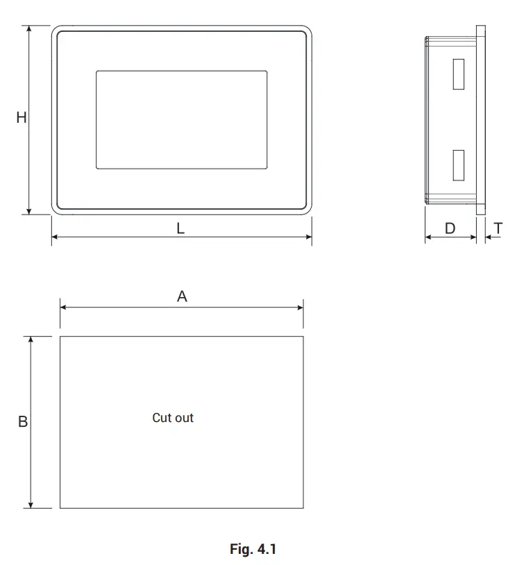
| MODEL | A | B | L | H | D | T |
| eSMART07 | 176mm/6.90” | 136mm/5.35” | 187mm/7.36” | 147mm/5.79” | 29mm/1.14” | 5mm/0.19” |
| eSMART07M | 176mm/6.90” | 136mm/5.35” | 187mm/7.36” | 147mm/5.79” | 29mm/1.14” | 5mm/0.19” |
| MODEL | A | B | L | H | D | T |
| eSMART10 | 271mm/10.66” | 186mm/7.32” | 282mm/11.10” | 197mm/7.75” | 29mm/1.14” | 6mm/0.23” |
Installation Environment
In order to meet the front panel protection classifications, proper installation procedure must be followed:
- the borders of the cutout must be flat
- screw up each fixing screw until the plastic bezel corner get in contact with the panel.
- the cutout for the panel must be of the dimensions indicated in this manual.
The equipment is not intended for continuous exposure to direct sunlight.
This might accelerate the aging process of the front panel film.
The equipment is not intended for installation in contact with corrosive chemical compounds. Check the resistance of the front panel film to a specific compound before installation.
Do not use tools of any kind (screwdrivers, etc.) to operate the touch screen of the panel.
The IP66 is guaranteed only if:
- max deviation from the plane surface to the cut-out: < 0.5mm
- thickness of the case where is mounted the equipment: from 1,5mm to 6mm
- max surface roughness where the gasket is applied: <120 um
A. Installation cut-out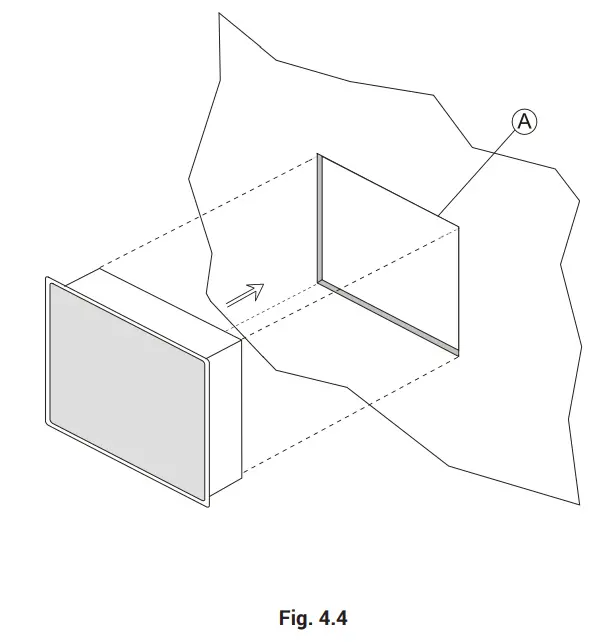
Safety instruction
For all installation notes, please refer to the Installation Guide provided with the product.
Installation Procedure
Place the fixing brackets contained in the fixing kit as shown in figure (Fig. 4.5).
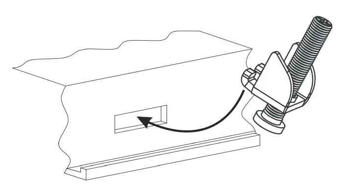
![]() CAUTION
CAUTION
Tightening torque: 75Ncm or screw each fixing screw until the bezel corner gets in contact with the panel.
Connections
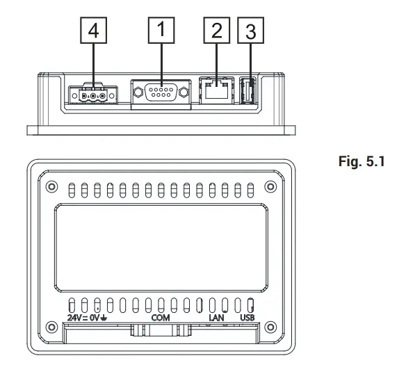
eSMART04
- Serial Port
- Ethernet Port
- USB Port
- Power Supply

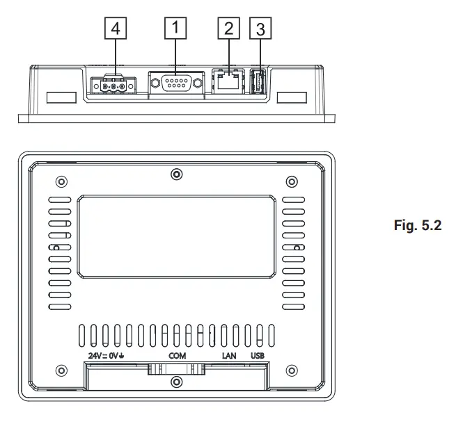
eSMART07
- Serial Port
- Ethernet Port
- USB Port
- Power Supply

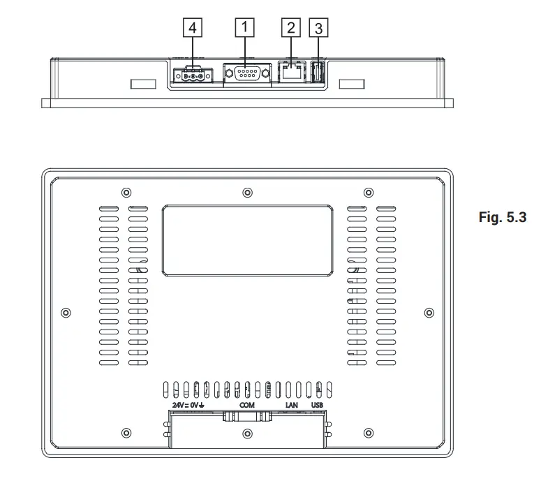
eSMART10
- Serial Port
- Ethernet Port
- USB Port
- Power Supply

Serial Port
The serial port is used to communicate with the PLC or with another type of controller. Standards available for the signals in the PLC port connector are: RS-232, RS-422, RS-485.
The serial port is software programmable. Make sure you select the appropriate interface in the programming software.
RS-232
| Pin | Description |
| 1 | GND |
| 2 | |
| 3 | TX |
| 4 | RX |
| 5 | |
| 6 | +5V output |
| 7 | CTS |
| 8 | RTS |
| 9 |
SERIAL PORT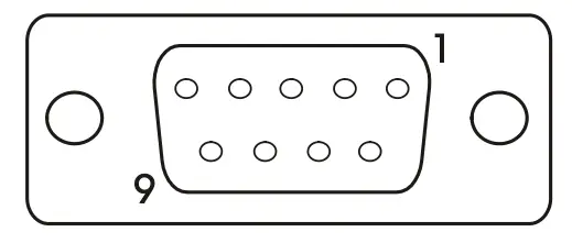
RS-422, RS-485
| Pin | Description |
| 1 | GND |
| 2 | |
| 3 | CHA- |
| 4 | CHB- |
| 5 | |
| 6 | +5V output |
| 7 | CHB+ |
| 8 | CHA+ |
| 9 |
The communication cable must be chosen for the type of device being connected.
Ethernet Port
The Ethernet port have two LED indicators for status. Please see description below.
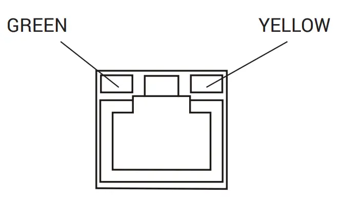
LED indicators
| Green | Yellow | |
| ON | OFF | No LAN cable connected |
| BLINK (link active) | ON | LAN cable connected with 100Mbit/s link |
| BLINK (link active) | OFF | LAN cable connected with 10Mbit/s link |
Power Supply, Grounding and Shielding
The power supply terminal block is shown in the figure below.
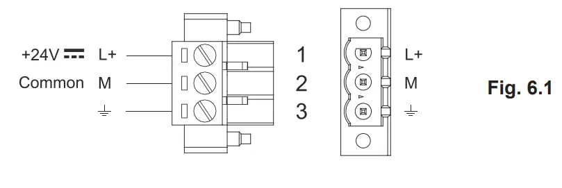
DC Power Connector – AWG24 wire size – R/C Terminal Blocks (XCFR2), Female pitch 5.08mm, torque 4.5 lb-in. 3 conductor 1,5mmq wire size minimum, minimum temperature conductor rating 105°C.
Note: Ensure that the power supply has enough power capacity for the operation of the equipment.
The unit must always be grounded to earth with 1.5mmq wire size minimum. Grounding helps limit the effects of noise due to electromagnetic interference on the control system.
Earth connection will have to be done using either the screw or the fast on terminal located near the power supply terminal block. A label helps identify the ground connection. Also connect to ground the terminal 3 on the power supply terminal block
The power supply circuit may be floating or grounded. In the latter case, connect to ground the power source common as shown in figure (see below) with a dashed line.
When using the floating power scheme, note that the HMI devices internally connects the power common to ground with a 1MΩ resistor in parallel with a 4,7nF capacitor.
The power supply must have double or reinforced insulation.
The suggested wiring for the power supply is shown in figure.
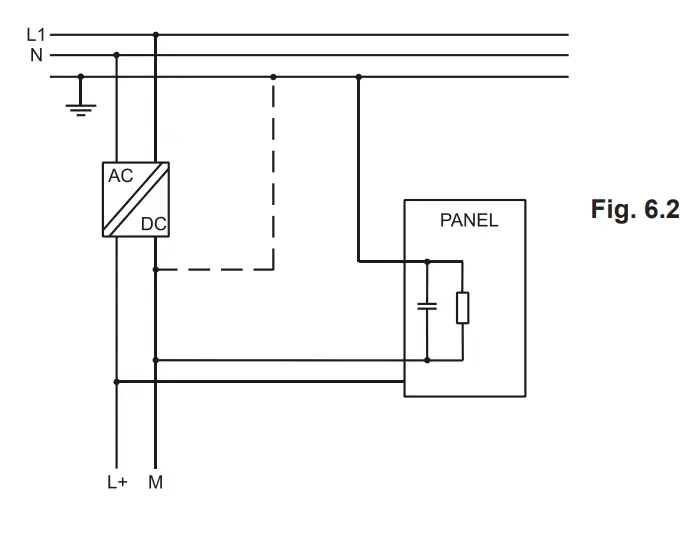
All the electronic devices in the control system must be properly grounded. Grounding must be performed according to applicable regulations.
Cleaning faceplates
The equipment must be cleaned only with a soft cloth and neutral soap product. Do not use solvents.
Getting Started
eSMART HMI products must be programmed with the software JMobile Studio (starting from v2.00). JMobile Studio is a software tool that must be properly installed on a computer running Microsoft Windows
There are two options to transfer a JMobile application project to a HMI device:
Ethernet: Connect the HMI device to the computer with an Ethernet network connection. From JMobile Studio choose the command Run/Download to target. You may have to ensu re that the proper firewall policy has been configured in the computer to allow JMobile Studio to access the network.
USB: Create an Update Package using JMobile Studio and copy it to a USB Flash drive.
Updated product documentation is available at www.exorint.com.
For the products described in this manual please check:
Systems Settings User Manual
JMobile Studio User Manual
Touchscreen calibration
eSMART HMI products support calibration of the interface. To start calibration proceed as follow:
- Use the “tap-tap” procedure at boot (this procedure consists in tapping the surface ofthe touchscreen during the device power-up phase. Tapping frequency must be high. You have to start tapping the touchscreen as soon as power has been applied to the device). When the sequence has been recognized, the system shows the message: “TAP-TAP DETECTED”.
- Release touch and wait few seconds until the message “ENTERING SYSTEM SETTINGS” appears
- Press and hold touch for few seconds for selecting “TOUCHSCREEN CALIBRATION”.
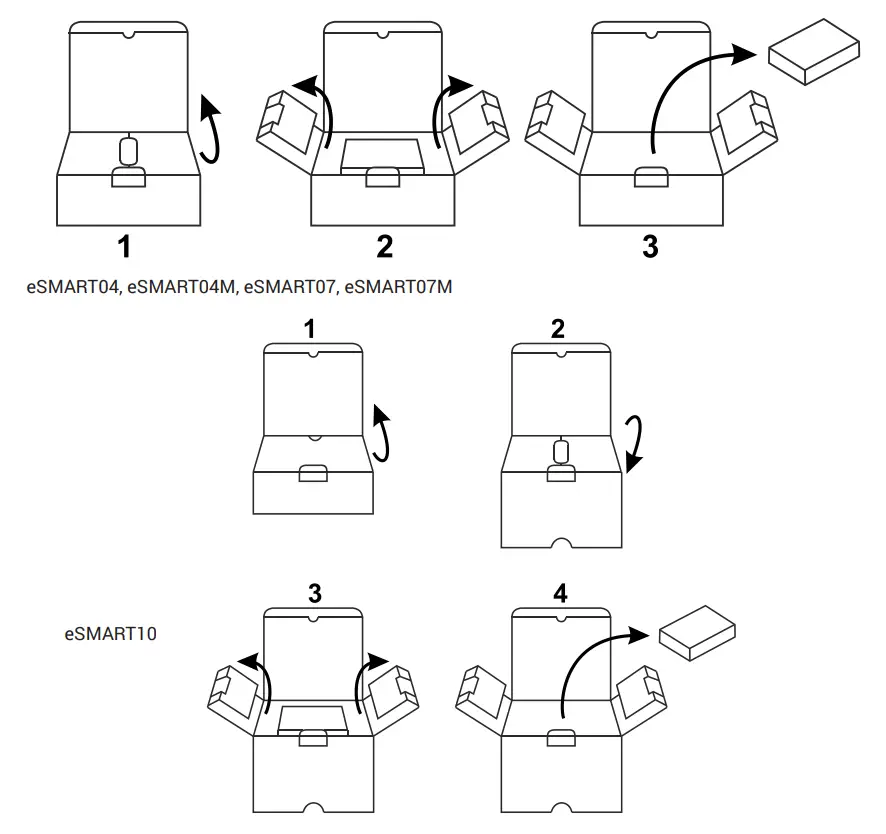
Unpacking and packing instructions
 Copyright © 2018-2020 Exor International S.p.A. – Verona, Italy. Subject to change without notice.
The information contained in this document is provided for informational purposes only. While efforts were made to verify the accuracy of the information contained in this documentation, it is provided “as is” without warranty of any kind.
Third-party brands and names are the property of their respective owners. www.exorint.com
Software available in these products is based on OpenSource. Visit oss.exorint.net for more details.
MANUGENESMARTxx – Version 2.04
© 2018-2022 EXOR International S.p.A. – Subject to change without notice