![]() ESP32 series development board
ESP32 series development board
User manual
ESP32 Series Development Board
Disclaimer and copyright notice
The information in this article, including the URL for reference, is subject to change without notice. The document is provided “as is” without warranty of any kind, including any warranties of merchantability, fitness for a particular purpose or non-infringement, and any warranties of any proposal, specification or sample referred to elsewhere. This document disclaims any liability, including any liability for any patent infringement arising from the use of the information contained herein. No estoppel or other license to use any intellectual property rights, express or implied, is granted herein.
The test data in this paper are all obtained by EBAI laboratory test, the actual results may be slightly different.
It is hereby stated that all trade names, trademarks and registered trademarks mentioned herein are the property of their respective owners.
Chengdu Yibai Electronic Technology Co., LTD reserves the right of final interpretation.
Note:
This manual is subject to change due to product version upgrade or other reasons. Ebai Electronic Technology Co., Ltd. reserves the right to modify the contents of this manual without any notice or prompt. This manual is for use only. Chengdu Ebaite Electronic Technology Co., Ltd. makes every effort to provide accurate information in this manual, but Chengdu Ebaite Electronic Technology Co., Ltd. does not guarantee that the content of this manual is completely free from error, and all statements, information and recommendations in this manual do not constitute any express or implied warranty.
Module introduction
1.1 Features
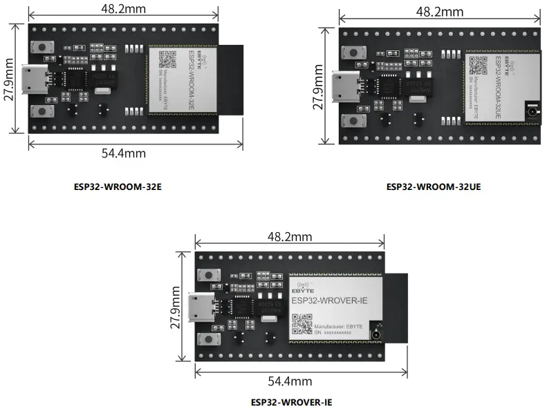
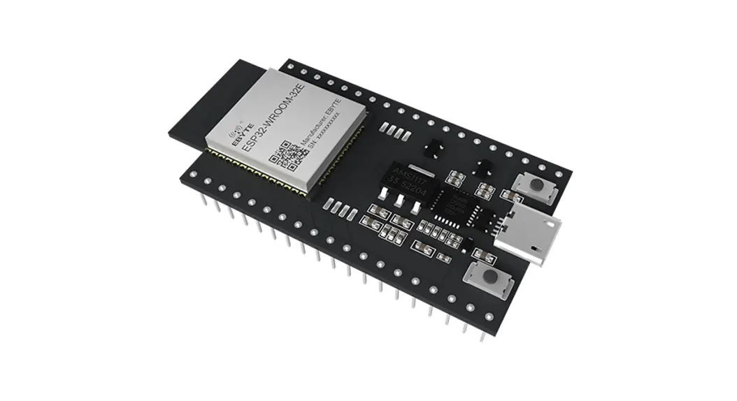
ESP32-WROVER-IE-TB 、ESP32-WROOM-32E-TB、ESP32-WROOM-32UE-TB are three entry-level development boards that use the corresponding modules of the ESP32 series as required. The development board has complete Wi-Fi and Bluetooth low power functions, and most of the pins of the module on the board have been drawn to the two sides of the pin row, developers can easily connect a variety of peripheral devices through jumper, and can also plug the development board into the breadboard for use.
1.2 Parameters
| Item | Parameter name | Value | Note |
| 1 | Support Modules | ESP32-WROVER-IE ESP32-WROOM-32E ESP32-WROOM-32UE | WiFi serial port module |
| 2 | Size | 48.2 * 27.9mm | USB connector included |
| 3 | Production process | Lead-free process, machine paste | Wireless products must be machine attached to ensure batch consistency and reliability |
| 4 | Power supply interface | USB | – |
| 5 | Communication interface | TTL | – |
| 6 | Working temperature | -40 ℃~ +85℃ | Industrial grade |
| 7 | Working humidity | 10%RH ~ 90%RH | Relative humidity, no condensation |
| 8 | Storage temperature | -40 ℃~ +125℃ | Industrial grade |
Function introduction
2.1 components
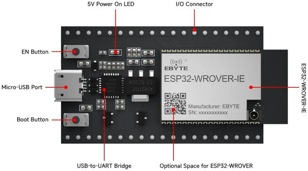 Figure 1 Main components The ESP32-WROVER-IE module is used as an example
| Item | Firmware | Introduction |
| 1 | ESP32 series of modules | A module based on the ESP32 series. For more information, please download the relevant materials from the official website |
| 2 | EN | Reset button. |
| 3 | Boot | Download button. Press and hold the Boot key, and press the EN key (do not release the Boot key at this time) to enter the Firmware Download mode, and download the firmware through the serial port. |
| 4 | USB-to-UART bridge | Single-chip USB-UART bridge that provides transfer rates of up to 3 Mbps. |
| 5 | Micro USB connector | The USB port can be used as the power supply for the circuit board or the communication port for connecting the PC to the ESP32 series module. |
| 6 | 5V Power On LED | When the development board is powered on (USB or external 5 V), the indicator will light up. See schematics in related documents for more information. |
| 7 | I/O | Most of the pins of the on-board module have been drawn to the development board’s row pins. Users can program ESP32 to realize PWM, ADC, DAC, I2C, I2S, SPI and other functions. |
Note: For specific function instructions, refer to the user manual of the ESP32 series corresponding module.
2.2 Pin definition
The following is a front view of ESP32-WROOM-32E-TB as an example:
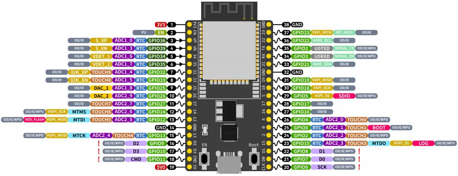 Figure 2. Current test interface diagram
| Pin number | Pin name | Type | Pin description |
| 1 | 3V3 | P | 3.3 V power supply |
| 2 | EN | I | CHIP_PU, Reset |
| 3 | VP | I | GPIO36, ADC1_CH0, S_VP |
| 4 | VN | I | GPIO39, ADC1_CH3, S_VN |
| 5 | IO34 | I | GPIO34, ADC1_CH6, VDET_1 |
| 6 | IO35 | I | GPIO35, ADC1_CH7, VDET_2 |
| 7 | IO32 | I/O | GPIO32, ADC1_CH4, TOUCH_CH9, XTAL_32K_P |
| 8 | IO33 | I/O | GPIO33, ADC1_CH5, TOUCH_CH8, XTAL_32K_N |
| 9 | IO25 | I/O | GPIO25, ADC1_CH8, DAC_1 |
| 10 | IO26 | I/O | GPIO26, ADC2_CH9, DAC_2 |
| 11 | IO27 | I/O | GPIO27, ADC2_CH7, TOUCH_CH7 |
| 12 | IO14 | I/O | GPIO14, ADC2_CH6, TOUCH_CH6, MTMS |
| 13 | IO12 | I/O | GPIO12, ADC2_CH5, TOUCH_CH5, MTDI |
| 14 | GND | G | Ground |
| 15 | IO13 | I/O | GPIO13, ADC2_CH4, TOUCH_CH4, MTCK |
| 16 | D2 | I/O | GPIO9, D2 |
| 17 | D3 | I/O | GPIO10, D3 |
| 18 | CMD | I/O | GPIO11, CMD |
| 19 | 5V | P | 5 V power supply |
| 20 | CLK | I/O | GPIO6, CLK |
| 21 | D0 | I/O | GPIO7, D0 |
| 22 | D1 | I/O | GPIO8, D1 |
| 23 | IO15 | I/O | GPIO15, ADC2_CH3, TOUCH_CH3, MTDO |
| 24 | IO2 | I/O | GPIO2, ADC2_CH2, TOUCH_CH2 |
| 25 | IO0 | I/O | GPIO0, ADC2_CH1, TOUCH_CH1, Boot |
| 26 | IO4 | I/O | GPIO4, ADC2_CH0, TOUCH_CH0 |
| 27 | IO16 | I/O | GPIO16 |
| 28 | IO17 | I/O | GPIO17 |
| 29 | IO5 | I/O | GPIO5 |
| 30 | IO18 | I/O | GPIO18 |
| 31 | IO19 | I/O | GPIO19 |
| 32 | GND | G | Ground |
| 33 | IO21 | I/O | GPIO21 |
| 34 | RX | I/O | GPIO3, U0RXD |
| 35 | TX | I/O | GPIO1, U0TXD |
| 36 | IO22 | I/O | GPIO22 |
| 37 | IO23 | I/O | GPIO23 |
| 38 | GND | G | Ground |
Note:
- P: power supply; I: input; O: output;
- Pins D0, D1, D2, D3, CMD, and CLK are used for internal communication between the ESP32 chip and the SPI flash and are centrally distributed on both sides of the development board near the USB port. In general, it is best if these pins are not connected, otherwise they may affect the work of SPI flash/SPI RAM.
- Pin GPIO16 and GPIO17 are only applicable to the onboard ESP32-WROOM series and ESP32-SOLO-1 development board. Pin GPIO16 and GPIO17 of the onboard ESP32-WROVER series development board are reserved for internal use.
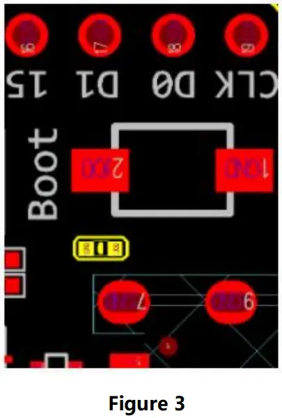
2.3 Notes
If you think C15 may affect the use of the development board, you can remove C15 completely.
The specific location of C15 on the development board is shown in the yellow section below.
Program burning guide
- Electricity before, please make sure that ESP32 WROVER – IE/ESP32 WROOM – 32 E/ESP32 – WROOM – UE is in good condition.
- Prepare tools: ESP32-WROVER-IE-TB /ESP32-WROOM-32E-TB/ ESP32-WROOM-32UE-TB, USB 2.0 data cable (standard type A to Micro-B, computer (Windows, Linux, or macOS). (Make sure you use the appropriate USB cable, some of which can only be used for charging, not for data transfer and programming.)
- Connected to the USB cable in PC software program burn;
Version
| Version | Revise date | Revise description | Maintenance person |
| 1 | 11/22/2022 | Initial version | Hao |
About us
 http://weixin.qq.com/r/NXTG3t-E_IKHrZu99yEn
Sales Hotline: 4000-330-990
Company Tel: 028-61399028
Technical support: [email protected]
Official website: https://www.es-ebyte.com
Company Address: Building B5, No. 199, West District
Avenue, High-tech West District, Chengdu City, Sichuan Province
![]() Copyright ©2012–2022
Copyright ©2012–2022
Chengdu Ebyte Electronic Technology Co.,Ltd


