![]() E78-400TBL-02 Test Kit
E78-400TBL-02 Test Kit
User Manual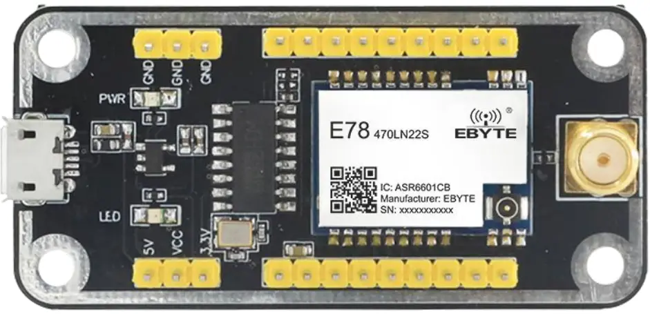
Disclaimer
The information in this document, including the URL address for reference, is subject to change without notice. The document is provided “as is” without any guarantee responsibility, including any guarantee for marketability, suitability for a specific purpose, or non-infringement, and any guarantee for any proposal, specification or sample mentioned elsewhere. This document does not bear any responsibility, including the responsibility for infringement of any patent rights caused by the use of the information in this document. This document does not grant any license for the use of intellectual property rights in estoppel or other ways, whether express or implied.
The test data obtained in the article are all obtained by the Ebyte laboratory, and the actual results may vary slightly.
We hereby declared that all brand names, trademarks and registered trademarks mentioned in this document are the property of their respective owners.
The final interpretation right belongs to Chengdu Ebyte Electronic Technology Co., Ltd.
Notice : Due to product version upgrades or other reasons, the contents of this manual may be changed. Ebyte Electronic Technology Co., Ltd. reserves the right to modify the contents of this manual without any hint or noticet. This manual is only used as a guide. Chengdu Ebyte Electronic Technology Co., Ltd. makes every effort to provide accurate information in this manual. However, we does not guarantee that the contents of the manual are completely free of errors. All statements, information and suggestions in this manual do not constitute any express or implied guarantee.
Introduction
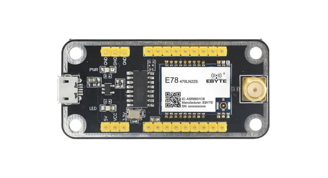
E78-400TBL-02 is a complete set of test products specially for E78 series SMD SOC modules combined with USB to TTL serial port backplane. All E78-470LN22S (6601) module pins have been drawn out for customer testing and development, which greatly reduces customer testing and development difficulty.
1.1 Size and interface specification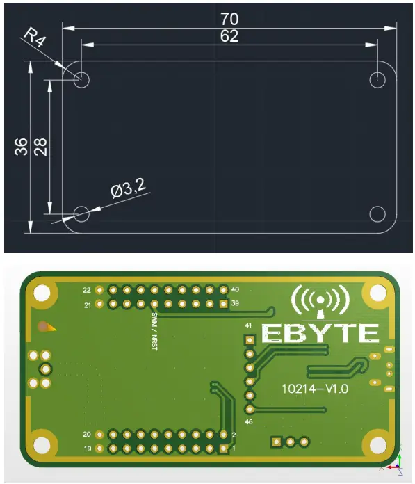
| Pin number | Definition | Function Description |
| 1 | LCD SEG8 | User-defined 10 pin |
| 2 | LCD SEG9 | User-defined 10 pin |
| 3 | LCD SEG11 | User-defined 10 pin |
| 4 | LCD SEG10 | User-defined 10 pin |
| 5 | LCD SEG13 | User-defined 10 pin |
| 6 | LCD SEG12 | User-defined 10 pin |
| 7 | LCD SEG15 | User-defined 10 pin |
| 8 | LCD SEG14 | User-defined 10 pin |
| 9 | LCD 5E617 | User-defined 10 pin |
| 10 | LCD SEG16 | User-defined 10 pin |
| 11 | I2C_SCL | Module I2C_SCL pin |
| 12 | I2C_SDA | Module I2C_SDA pin |
| 13 | ADC_IN1 | Module ADC_IN1 input pin |
| 14 | ADC_INO | Module ADC_INO input pin |
| 15 | GPI03 | User-defined 10 pin |
| 16 | GPIO2 | User-defined 10 pin |
| 17 | ADC_IN2 | Module ADC_IN2 input pin |
| 18 | GP104 | User-defined 10 pin |
| 19 | GND | Baseboard reference ground |
| 20 | GND | Baseboard reference ground |
| 21 | GND | Baseboard reference ground |
| 22 | GND | Baseboard reference ground |
| 23 | SPISICK | Module SPI_SLCK pin |
| 24 | SPINSS | Module SPI NSS pin |
| 25 | SPI_MOSI | Module SPI_MOSI pin |
| 26 | SPI_MISO | Module SPI_MISO pin |
| 27 | LCD_SEG2 | User-defined 10 pin |
| 28 | LCD_SEG1 | User-defined 10 pin |
| 29 | NRST | Module external reset pin |
| 30 | SWIM | Module SWIM pin |
| 31 | LCD COM1 | User-defined 10 pin |
| 32 | LCD COMO | User-defined 10 pin |
| 33 | VREFP | Module ADC reference voltage input pin |
| 34 | LCD COM2 | User-defined 10 pins |
| 35 | UART1 TX | Module UART1 TX pin |
| 36 | UARTLFOC | Module UART1 RX pin |
| 37 | LCD SEGO | User-defined 10 pins |
| 38 | VI.CD | Module VLCD pin, when it is LCDxx. the pin should be connected to the power supply 3.3V |
| 39 | LCD_SEG3 | User-defined 10 pins |
| 40 | LCD COM3 | User-defined 10 pins |
| 41 | LCD_SE-G4 | User-defined 10 pins |
| 42 | LCD SECS | User-defined 10 pins |
| 43 | UARTO FOC | Module UARTO_RX pin |
| 44 | UARTO TX | Module UARTO TX pin |
| 45 | LCDSEG6 | User-defined 10 pins |
| 46 | LCD_SEG7 | User-defined 10 pins |
Quick start
2.1 Test preparation
2.1.1 Driver Installation
Please go to the official website to download the driver CH341SER.EXE, and double-click to install. This driver supports 32/64-bit Windows 10/8.1/8/7/VISTA/XP, SERVER2016/2012/2008/2003, 2000/ME/98, certified by Microsoft digital signature, and supports USB to 3-wire and 9-wire serial ports etc.
2.1.2 hardware connection
Please prepare the Micro USB cable and antenna, connect them to the E78-400TBL-02 accordingly, and open the corresponding serial port. 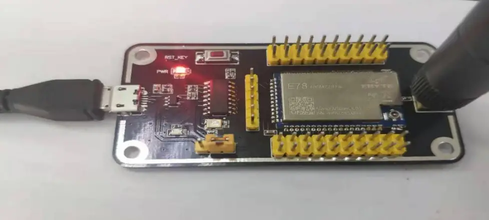 As shown in the figure, plug in the jumper cap and select 3.3V power supply. Both E78-400TBL-02 are configured in this way. Open the corresponding serial port to send and receive data.
Since the E78 series has no factory firmware, if you want to send and receive data through the serial port, please program it.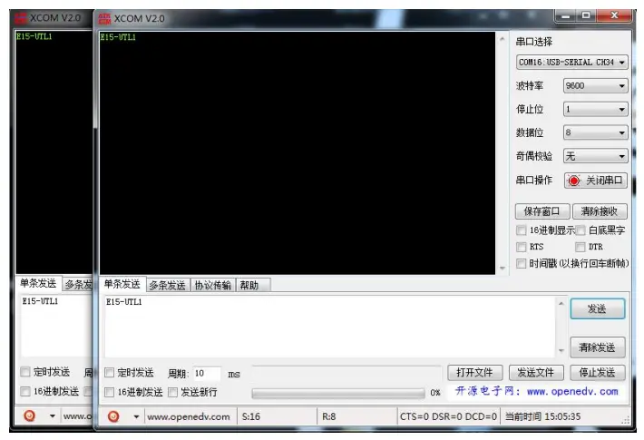
About us
![]() Technical support: [email protected]
Technical support: [email protected]
Documents and RF Setting download link: www.cdebyte.com
Thank you for using Ebyte products! Please contact us with any questions or suggestions: [email protected]
Official hotline:028-61399028
Web: www.cdebyte.com
Address: , Building B5, Mould Industrial
Park, 199# Xiqu Ave, High-tech Zone
Chengdu, 611731, Sichuan, China
Copyright ©20122022Chengdu
Ebyte Electronic Technology Co., Ltd.


