EBYTE MBL Series RCE220-400MLB-01 Evaluation Kit
Disclaimer
EBYTE reserves all rights to this document and the information contained herein. Products, names, logos and designs described herein may in whole or in part be subject to intellectual property rights. Reproduction, use, modification or disclosure to third parties of this document or any part thereof without the express permission of EBYTE is strictly prohibited. The information contained herein is provided “as is” and EBYTE assumes no liability for the use of the information. No warranty, either express or implied, is given, including but not limited, with respect to the accuracy, correctness, reliability and fitness for a particular purpose of the information. This document may be revised by EBYTE at any time. For most recent documents, visit www.ebyte.com.
Note:
The contents of this manual are subject to change due to product version upgrades or other reasons.Chengdu Ebyte Electronic Technology Co.,Ltd. reserves the right to make changes to the contents of this manual without notice or suggestion.This manual serves only as a user guide and Chengdu Ebyte Electronic Technology Co.,Ltd. endeavours to provide accurate information in this manual, but Chengdu Billionaire Electronics Co., Ltd. does not ensure that the contents are completely error-free and that all statements, information and suggestions in this manual do not constitute any express or implied warranty.
Product Overview
Brief Introduction
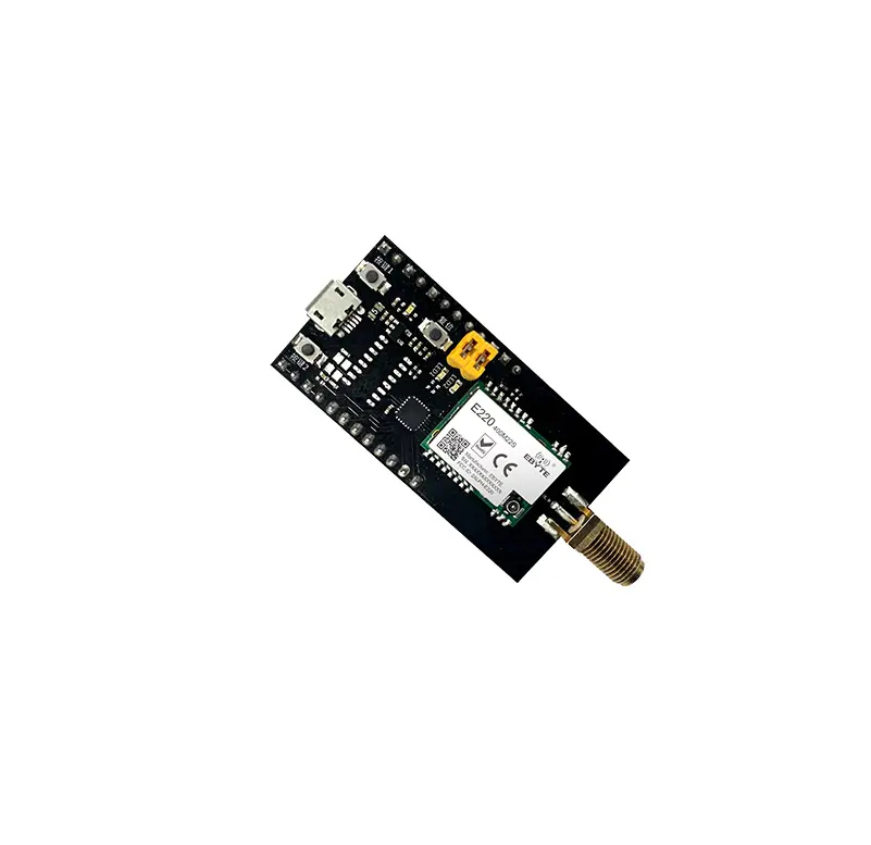
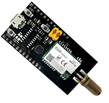
The MBL series evaluation kits are designed to help users quickly evaluate Ebyte’s new generation package compatible wireless modules. Most of the pins on the board have been led out to the pin headers on both sides, developers can easily connect a variety of peripheral devices through jumpers according to actual needs. The kit provides complete software application examples to help customers quickly get started with wireless data communication development. Different types of Sub-1G wireless modules can be mounted on-board according to customer needs. All supported modules have pin-compatible packages that can be quickly replaced.
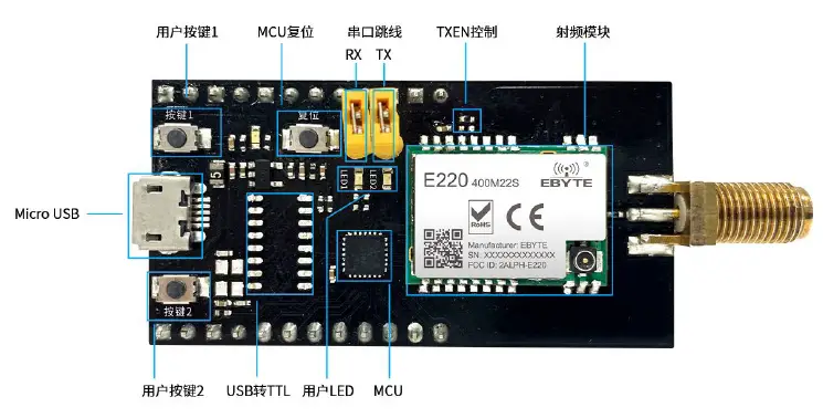
Size, interface description
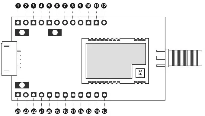
| No. | Definition | Function Description |
| 1 | 3.3V | 3.3V Electric pin |
| 2 | 3.3V | 3.3V Electric pin |
| 3 | GND | Floor reference ground |
| 4 | GND | Floor reference ground |
| 5 | 3.3V | 3.3V Electric pin |
| 6 | GND | Floor reference ground |
| 7 | REST | MCUExternal reset pin |
| 8 | SWIM | SWIM pin of MCU |
| 9 | 3.3V | 3.3V Electric pin |
| 10 | VCC | Module power supply pin, need to be short-circuited with pin 9 to supply power to the module |
| 11 | PC6 | MCU ordinary IO |
| 12 | PC5 | MCU ordinary IO |
| 13 | PB3 | MCU ordinary IO |
| 14 | PB2 | MCU ordinary IO |
| 15 | PB1 | MCU ordinary IO |
| 16 | PB0 | MCU ordinary IO |
| 17 | M1 | Module mode switch pin (see module product manual for details) |
| 18 | M0 | Module mode switch pin (see module product manual for details) |
| 19 | PD1 | MCU ordinary IO |
| 20 | PD0 | MCU ordinary IO |
| 21 | GND | Floor reference ground |
| 22 | GND | Floor reference ground |
| 23 | 5V | 5V Electric pin |
| 24 | 5V | 5V Electric pin |
Support list
| RF Chip | Manufacturer | Module model | |
| 1 | CC1101 | Texas Instruments | E07-400M10S |
| 2 | CC1101 | Texas Instruments | E07-900M10S |
| 3 | SI4438 | Silicon Labs | E30-400M20S |
| 4 | SI4463 | Silicon Labs | E30-900M20S |
| 5 | LLCC68 | Semtech | E220-400M22S |
| 6 | LLCC68 | Semtech | E220-900M22S |
| 7 | SX1278 | Semtech | E32-400M20S |
| 8 | SX1276 | Semtech | E32-900M20S |
| 9 | SX1268 | Semtech | E22-400M22S |
| 10 | SX1262 | Semtech | E22-900M22S |
Software Description
Directory Structure
| Matter | Explanation | |
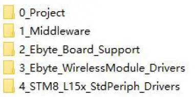
| 1 | File Directory | You can download the sample project from the official website, open the directory as shown in the figure below
|
| 2 | Catalog description | You can use the IAR For STM8 development environment to find the entry file to open the project |
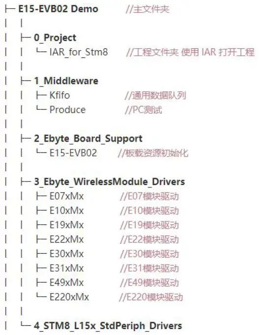 |
IAR Project
| Matter | Explanation | |
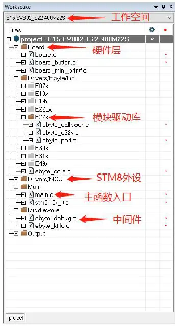
| Engineering structure | Use the IAR For STM8 development environment to open the project and you can see the basic structure |
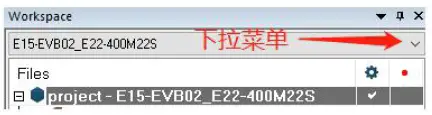
| Switch workspace | The global macro definition and file path are defined in the C/C++ Compiler option to distinguish the driver files of different modules. When switching workspaces, different macro definitions will be used to switch the driver files of different modules
Changed the Exclude from build property of Drivers/Ebyte/RF, that is, select the target module driver folder to participate in the compilation process. Changed the Additional include in the project C/C++ Compiler, that is, specify the module driver file path. The Defined symbols in the project C/C++ Compiler have been changed, that is, global macro definitions have been defined to help configure the module driver properties.
|
Main function
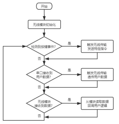
The main function entry is in main.c. The demonstration function process is simplified as follows:
| Item | Explanation | |
| 1 | Key Function | If a button is pressed, the command data will be sent wirelessly. In essence, it means sending a specific string “ping” and expecting to receive a response “pong” |
| 2 | Serial data transfer to wireless transmission | After the serial port receives the data, it automatically starts to transmit the data wirelessly. Of course, it contains some special command responses, which are mainly used for special tests and can be ignored by the user. After the sending is completed, the user function will be automatically called back to handle the sending logic by itself. |
| 3 | Receive data wirelessly | Generally, the internal status identifier of the module is read to determine whether there is data, and the underlying driver will copy the data and pass it to the user callback function, so as to process the receiving logic by itself |
The software process is simplified as shown in the figure below:
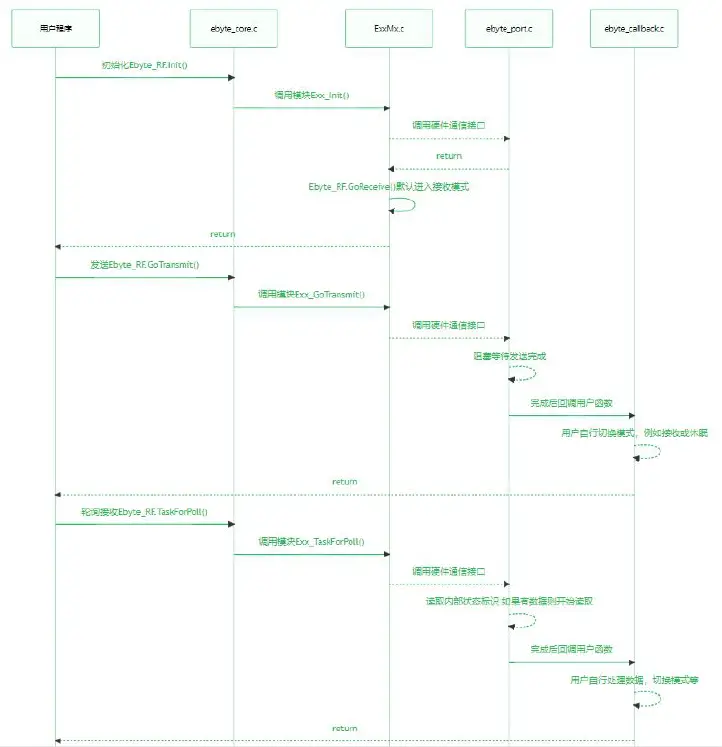
Transceiving timing
The wireless module has multiple operating states, and can only perform specific functions in the corresponding state. From the simplest way of sending and receiving data, only the sending mode and the receiving mode are considered.
| Item | Explanation | |
| 1 | Receive mode | After the default initialization is completed, it will automatically enter the receiving mode. In essence, the receiving function is called during initialization, and the receiving mode is entered. If you need to consider entering other modes after initialization, such as sleep, just replace it with the same type of function Go_xxxxx(). |
| 2 | Send mode | When calling the sending function, the bottom driver actually switches the module into the standby mode first, and usually completes the modulation parameter configuration in this mode, such as frequency, power, frequency offset, etc. After the parameter configuration is correct, gradually enter some intermediate modes, turn on the internal FIFO, PA, external XTAL, etc., and the current consumption also gradually rises. Finally, it switches to the sending mode and triggers wireless data transmission. After completion, the module enters the standby mode. In this state, it cannot continue to send and receive. The user needs to handle the next mode in the callback function. When the function is complicated, continuous reception or continuous transmission is required. Please switch to other modes according to the characteristics of the chip. |
The timing diagram is as follows:
Programming
| File | Key note | |
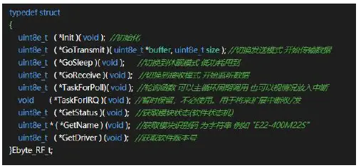
| 1 | ebyte_core.h | A module structure is defined to abstract the basic functions, and the functions of the underlying module will be bound to this structure. When used for simple sending and receiving applications, there is no need to understand the underlying working details of each module, and you can start sending and receiving data directly by calling the abstracted function. If you need to customize some functions, you can also consider integrating them into the structure. If you know enough about the functional functions of the underlying module, you can also directly remove the ebyte_core.c/h file, and there is |
| no strong coupling between the layers 。
| ||
| 2 | ebyte_exx.c | It is a specific module driver file, which is usually packaged and does not need to be modified by the user. You only need to consider how to input and output data from this “box”. |
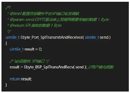
| 3 | ebyte_port.c | It is specially used to bind SPI and GPIO under different hardware platforms, abstracted as “box” input. The user needs to fill the communication interface in his hardware platform to a fixed position according to the comment. Generally speaking, it is to provide the SPI transceiver function and pin level control. Some modules are slightly special. For example, E49 uses half-duplex SPI. If you are too lazy to write a communication driver, you can directly bind the IO to a fixed location, and leave the rest to the module to drive its own analog IO to achieve communication. As shown in the figure below, in the comments, it is required to provide the SPI interface location to fill in the specific transceiver function, send the SPI to send data, and the result to return the SPI
to receive data. |
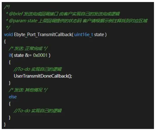
| ebyte_callback.c | It is specially used to bind the user’s own sending and receiving logic, abstracted as the output of the “box”. Essentially, the module driver directly calls the user’s callback function after confirming that the sending or receiving is completed. As shown in the figure below, just fill in the user’s logic function at the To-do prompt. The state is transmitted by the module driver, and is actually processed by the Exx_GoTransmit() function. When the function is complicated, you can consider modifying it to support |
| more situations.
| ||
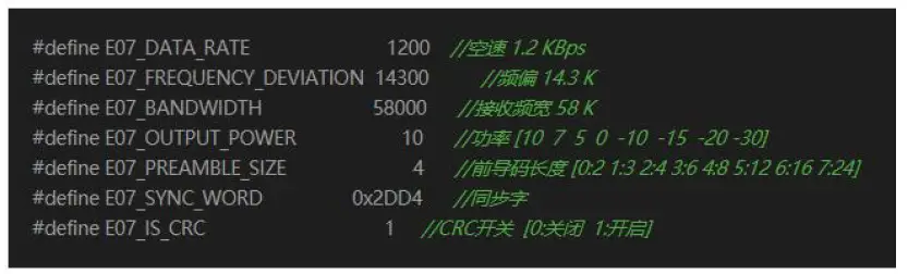
| ebyte_exx.h | Some conventional modulation parameters are defined, which generally do not need to be modified, and can be adjusted by themselves. Note that when modifying, please understand the explanation in the comment. There is a range check for the parameters in the module driver, and the wrong modulation parameter will cause the initialization to fail. The following figure shows FSK modulation parameters:
| |
| board.c | STM8 peripheral initialization, involving SPI, TIMER, GPIO, etc., is strongly coupled with the hardware used. | |
| board_button.c | The key event queue is a FIFO in terms of data structure. After the timer detects the button, it will store the corresponding event in the queue and wait for the main loop to respond. | |
| board_mini_printf.c | Simplified printf, although the function is reduced, but it takes up a small volume. The DEBUG macro in the project mainly depends on the mprintf provided by this file. | |
| ebyte_kfifo.c | Used for serial port data reception, optimized general-purpose FIFO queue, suitable for high-speed cache. | |
| ebyte_debug.c | It is used to connect to a PC for some tests and generally does not need to be used. | |
| stm8l15x_it.c | All interrupt function entrances will focus on the interrupt service functions such as serial port, timer, button IO, etc. |
Quick demo
Signal line connection
| File | Key note | |
| 1 | Serial jumper cap | 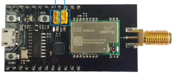 |
| 2 | RF module jumper cap | 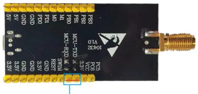 |
| 3 | Assist | USB cable, PC, etc. |
Serial port assistant
| Matter | Explanation | |
| 1 | Device manager View serial port number | 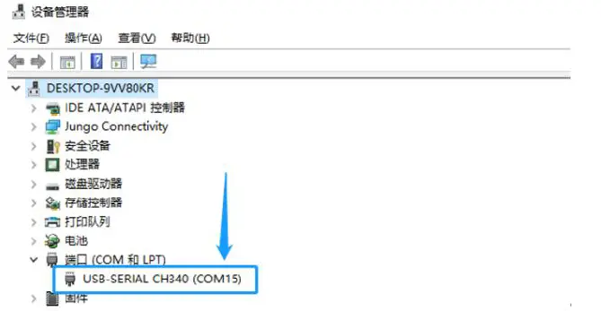 |
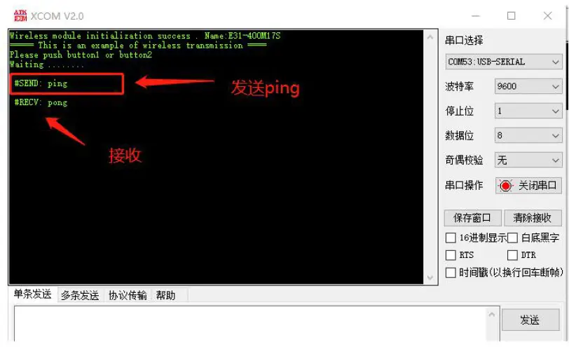
| 2 | Serial port software |  |
| 3 | Push button communication example | #RECV Identifier, only used as a reminder, indicates the data received by the wireless module. #SEND Identifier, only for reminding, indicating the data sent by the wireless module
|
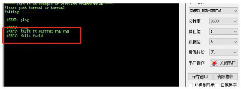
| 4 | Serial data transmission | Serial data transmission through XCOM direct transmission of required content
|
Common problem
Unsatisfactory transmission distance
- When there is a straight line communication obstacle, the communication distance will be attenuated accordingly;
- Temperature, humidity, and co-frequency interference will increase the communication packet loss rate;
- The ground absorbs and reflects radio waves, and the test effect is poor when it is close to the ground;
- Sea water has a strong ability to absorb radio waves, so the seaside test effect is poor;
- If there is a metal object near the antenna or placed in a metal shell, the signal attenuation will be very serious;
- The power register is set incorrectly, and the air speed is set too high (the higher the air speed, the closer the distance);
- The low voltage of the power supply at room temperature is lower than the recommended value, and the lower the voltage, the lower the power output;
- The matching degree of the antenna and the module is poor or the quality of the antenna itself is problematic.
Module is easily damaged
- Please check the power supply to ensure that it is within the recommended power supply voltage. If it exceeds the maximum value, it will cause permanent damage to the module;
- Please check the stability of the power supply, and the voltage should not fluctuate significantly and frequently;
- Please ensure that the installation and use process is anti-static, and high-frequency components are electrostatically sensitive;
- Please ensure that the humidity should not be too high during installation and use, and some components are humidity sensitive devices;
- If there is no special requirement, it is not recommended to use at too high or too low temperature
Bit error rate is too high
- There is co-frequency signal interference nearby, stay away from the interference source or modify the frequency and channel to avoid interference;
- Unsatisfactory power supply may also cause garbled codes. Be sure to ensure the reliability of the power supply;
- Poor or too long extension cables and feeders can also cause high bit error rates.
Revise history
| Version | Date | Revision description | Issued by |
| 1.0 | 2021-09-22 | Initial version | JH |
About us
- Technical support: [email protected]
- Documents and RF Setting download link: www.ebyte.com
- Thank you for using Ebyte products! Please contact us with any questions or suggestions: [email protected]
- Phone: +86 028-61399028
- Web: www.ebyte.com
- Address: B5 Mould Park, 199# Xiqu Ave, High-tech District, Sichuan, China


