![]() ITEM # GEN1000I
ITEM # GEN1000I
1,000 SURGE WATTS / 800 RUNNING WATTS
GASOLINE INVERTER GENERATOR INSTRUCTION MANUAL![]()
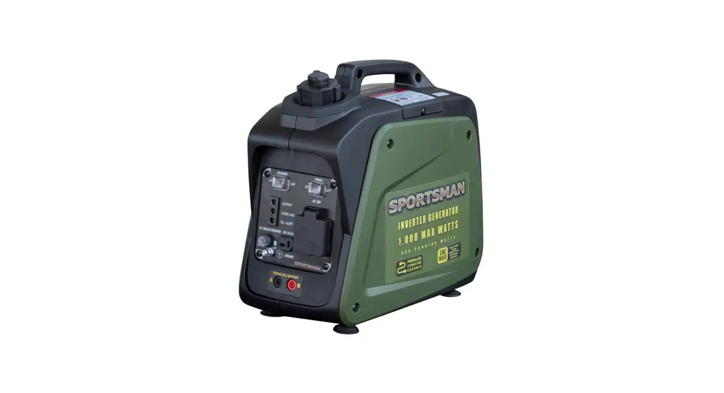
GEN1000I Gasoline Inverter Generator
READ ALL INSTRUCTIONS AND WARNINGS BEFORE USING THIS PRODUCT.
This manual provides important information on proper operation & maintenance. Every effort has been made to ensure the accuracy of this manual. These instructions are not meant to cover every possible condition and situation that may occur. We reserve the right to change this product at any time without prior notice.
IF THERE IS ANY QUESTION ABOUT A CONDITION BEING SAFE OR UNSAFE, DO NOT OPERATE THIS PRODUCT!
If you experience a problem, have questions or need parts for this product, call Customer Service at 1-866-460-9436, Monday-Friday, 8 AM – 4 PM Central Time. A copy of the sales receipt is required.
OR CONSUMER USE ONLY – NOT FOR PROFESSIONAL USE. KEEP THIS MANUAL, SALES RECEIPT & APPLICABLE WARRANTY FOR FUTURE REFERENCE.
ATTENTION: OIL AND GASOLINE IS NOT INCLUDED WITH THE GENERATOR AND MUST BE ADDED BEFORE FIRST USE.
ATTENTION: THIS GENERATOR IS NOT INTENDED TO POWER MEDICAL DEVICES OR LIFE SUPPORT APPLIANCES.
ATTENTION: FOLLOW ENGINE BREAK-IN PROCEDURE FOR FIRST 20 HOURS OF USE.
ATTENTION: DO NOT EXCEED MAX WATTAGE CAPACITY, OTHERWISE DAMAGE CAN OCCUR TO GENERATOR AND/OR
APPLIANCES. FOLLOW WATTAGE GUIDE TO DETERMINE PROPER STARTING & RUNNING WATTS.
 To register your product warranty, please visit buffalotools.com or scan the QR code.
FEATURES:
- 1000 Surge Output / 800 Running Watts*
- 120V Operation
- 1.3 HP Engine, 4 Stroke , 5500 RPM
- Displacement (CC): 40cc
- Low Oil Shut Off
- UL Listed Electrical Components
- Engine Shut Off Switch
- Power Outlets
- Power Your Sensitive Electronics With Stable, Constant Voltage
- 1-12V DC Outlet
- 1-120V Outlets
- 0.55 Gallon Max Capacity Gasoline Fuel Tank
- Complies with EPA emissions
- Decibel Rating < 56 db 0% load measured at 23 feet
- Run time = 6.3 hrs @ 50% load Gasoline
- Fuel Type: Unleaded Gasoline Only 87 rating or higher
- This portable generator is not for use with gasoline/ ethanol blends with over 15% ethanol. Do not use E85 fuel.
- If you are using a generator 3,000 feet above sea level, it may not function properly because of air flow getting through the carburetor.
- High Altitude Use: This generator is not recommended for high altitude use 3,000 feet above sea level.
Included with this Generator:
- DC connector wires for connecting 12 Volt automotive-type batteries
- Spark plug wrench
- Screwdriver
2 YEAR LIMITED EMISSION-RELATED WARRANTY
THIS ENGINE MEETS U.S. EPA EMISSION STANDARDS UNDER 40 CFR 1054.625 .The emission-related limited warranty is valid for two (2) years. Keep the purchase receipt and mail in the product registration card for proof of purchase. Buffalo Corp limits emission-related warranty repairs to authorized service centers for owners located within 100 miles of an authorized service center. For owners located more than 100 miles from an authorized service center, Buffalo Corp will, in its sole discretion, either pay for shipping costs to and from an authorized service center, provide for a service technician to come to the owner to make the warranty repair, or pay for the repair to be made at a local non-authorized service center. The provisions of this paragraph apply only for the contiguous states, excluding the states with high-altitude areas identified in 40 CFR part 1068, Appendix III.
To exercise this warranty, DO NOT RETURN TO RETAILER. Instead, call Customer Service toll free at 1-866-460-9436 (email address [email protected]) and you will be instructed on where to take the engine for warranty service. Take the generator and proof of purchase (your receipt) to the repair facility recommended by the Customer Service Representative. The warranty does not extend to generators damaged or affected by fuel contamination, accidents, neglect, misuse, unauthorized alterations, use in an application for which the product was not designed and any other modifications or abuse.
1 YEAR LIMITED WARRANTY (30 Day Limited for Commercial/Rental Purpose)
Generators are warranted to be free from defects in materials and workmanship for a period of 1 YEAR from date of original purchase. Buffalo Corp. is not liable for any indirect, incidental or consequential damages from the sale or use of this product. Any implied warranties are limited to 1 YEAR as stated, or as otherwise stated, in this written limited warranty. Some states do not allow the exclusion or limitation of incidental or consequential damages. Some states do not allow limitation on the length of an implied warranty. Buffalo Corp will repair or replace, at its discretion, any part that is proven to be defective in materials or workmanship under normal use during the 1 YEAR warranty period. Warranty repairs or replacements will be made without charge for parts or labor. Parts replaced during warranty repairs will be considered as part of the original product and will have the same warranty period as the original product. This warranty gives you specific legal rights, and you may have other rights that vary state to state.
Notice Regarding Emissions:
Engines certified to comply with California and U.S. EPA emission regulations for SORE (Small Off Road Equipment) are certified to operate on regular unleaded gasoline and may include the following emission control systems: Three-Way Catalyst (TWC) (if equipped), and Engine Modifications (EM).
Legal Requirements:
Federal and/or State Occupational Safety and Health Administration (OSHA) regulations, local codes, and/or ordinances may apply to the intended use of this generator. Consult a qualified electrician, electrical inspector, and/or the local agency having jurisdiction. Some areas require generators to be registered with local utility companies. Additional regulations may apply if this generator will be used at a construction site.
IMPORTANT SAFETY INSTRUCTIONS
STOP!
Before using this generator, if you have any questions regarding the hazard and safety notices listed in this manual and/or on this generator, call 1-866-460-9436, Monday – Friday, 8 AM – 4 PM Central Time.![]() DANGER: Carbon Monoxide Gas: When in operation, the exhaust from this generator contains poisonous carbon monoxide gas. Carbon monoxide gas is both odorless and colorless AND may be present even if you do not see or smell gas. Breathing this poison gas can lead to headaches, dizziness, drowsiness, loss of consciousness and eventually death.
DANGER: Carbon Monoxide Gas: When in operation, the exhaust from this generator contains poisonous carbon monoxide gas. Carbon monoxide gas is both odorless and colorless AND may be present even if you do not see or smell gas. Breathing this poison gas can lead to headaches, dizziness, drowsiness, loss of consciousness and eventually death.
- USE THIS GENERATOR ONLY OUTDOORS IN NON-CONFINED AREAS. DO NOT SECURE THE GENERATOR WITH A CHAIN OR ROPE, AS THIS WILL MAKE IT DIFFICULT TO MOVE IN AN EMERGENCY.
- Keep at least several feet of clearance on all sides to allow proper ventilation for this generator.
![]() WARNING: Flammable Gasoline: This generator may emit highly flammable and explosive gasoline vapors, which can cause severe burns or even death. A nearby open flame can lead to an explosion even if not directly in contact with gasoline.
WARNING: Flammable Gasoline: This generator may emit highly flammable and explosive gasoline vapors, which can cause severe burns or even death. A nearby open flame can lead to an explosion even if not directly in contact with gasoline.
- Do not operate this generator near open flame.
- Do not smoke near this generator.
- Always operate this generator on a firm, level surface. Gasoline is highly flammable and explosive. Handling fuel can result in serious injury or burns.
- Always shut down this generator before refueling. Refuel in a well-ventilated area. Keep heat, sparks and flame away while refueling and away from the location where gasoline is stored. Never refuel indoors where gasoline fumes may reach flames and/or sparks.
- Allow this generator to cool for at least 2 minutes before removing the fuel tank cap. Loosen the cap slowly to relieve pressure in the fuel tank. Avoid spilling fuel.
- Do not fill the fuel tank above the upper limit line. Gasoline may expand during operation. Do not fill to the top of the tank.
- Always check for spilled gasoline and immediately wipe it up before starting this generator.
- Empty the fuel tank before storing or transporting this generator.
- Always handle fuel outdoors.
- Before transporting, turn the fuel valve to the “OFF” position and disconnect the spark plug.
NOTE: DO NOT USE GASOLINE CONTAINING MORE THAN 10% ETHANOL (e10).![]() DANGER: Usage: Prolonged exposure to high noise levels can be hazardous to hearing. Always wear ANSI-approved hearing protection when operating or working around the generator when it is running.
DANGER: Usage: Prolonged exposure to high noise levels can be hazardous to hearing. Always wear ANSI-approved hearing protection when operating or working around the generator when it is running.![]() DANGER: Powerful Voltage: This generator produces powerful voltage, which can result in electrocution.
DANGER: Powerful Voltage: This generator produces powerful voltage, which can result in electrocution.
- ALWAYS ground this generator before using it. (See “Ground the Generator” section in this manual).
- Only electrical devices should be plugged into this generator, either directly or with an extension cord. NEVER connect a building electrical system to this generator without a qualified electrician. Doing so voids your warranty. Such connections must isolate generator power from utility power and comply with local electrical laws and codes. Failure to comply can create a back feed into utility lines creating an electrocution hazard, which may result in serious injury or death to utility workers. Such a back feed may cause this generator to explode, burn and create fires when utility power is restored.
- Use a ground fault circuit interrupter (GFCI) in highly conductive areas such as metal decking or steel work. GFCIs are available in-line with some extension cords.
- Do not use this generator in wet conditions (rain, snow, active sprinkler system, wet hands, etc.). Always keep this generator dry and operate it with dry hands.
- Do not allow children or non-qualified persons to operate this generator.
![]() WARNING:
WARNING:
GASOLINE IS HIGHLY FLAMMABLE AND EXPLOSIVE. YOU COULD BE BURNED OR SERIOUSLY INJURED IF THE GASOLINE IS IGNITED. Before refueling, stop the engine and keep heat, sparks and flame away. Handle fuel only outdoors. Do not fill the fuel tank above the upper limit line. Wipe up spills immediately.![]() WARNING:
WARNING:
IMPROPER CONNECTIONS TO A BUILDING CAN ALLOW ELECTRICAL CURRENT TO BACKFEED INTO UTILITY LINES, CREATING AN ELECTROCUTION HAZARD. Connections to a building must isolate generator power from utility power and comply with all applicable laws and electrical codes.![]() DANGER:
DANGER:
High Temperatures: This generator produces heat when in operation. Temperatures near the exhaust can exceed 150 Degrees Fahrenheit (65 Degrees Celsius).
- Do not touch hot surfaces. Observe all warning placards on this generator denoting hot surfaces.
- Allow this generator to cool for several minutes after use before touching the engine, muffler or other areas that are hot during operation and before storing indoors.
- Hot exhaust may ignite some materials. Keep flammable materials away from this generator.
- Keep at least several feet of clearance on all sides of this generator during operation. Do not enclose this generator in any structure.
![]() DANGER:
DANGER:
Usage: Misuse of this generator can damage it or shorten its life.
- Use this generator only for its intended purpose.
- Operate this generator only on a dry, level surface. Do not secure the generator with a chain or rope, which would prevent it from being moved in an emergency.
- Allow this generator to run for several minutes before connecting any electrical devices.
- Promptly turn off any malfunctioning devices and disconnect them.
- Do not operate an excessive number of electrical devices in excess of the wattage capacity of this generator.
- Do not turn on electrical devices until after they are connected to this generator.
- Turn off all connected electrical devices before stopping this generator.
![]() WARNING:
WARNING:
Usage: Avoid the use of extension cords if possible. If you choose to use them, be sure they are sized adequately to handle the flow of electricity. An undersized cord can overheat, short out and cause a fire.![]() DANGER:
DANGER:
EXHAUST CONTAINS POISONOUS CARBON MONOXIDE GAS THAT CAN BUILD UP TO DANGEROUS LEVELS IN CLOSED AREAS. BREATHING CARBON MONOXIDE CAN CAUSE UNCONSCIOUSNESS OR DEATH. Never run the generator in a closed or even partly closed area where people may he present.
DESCRIPTION
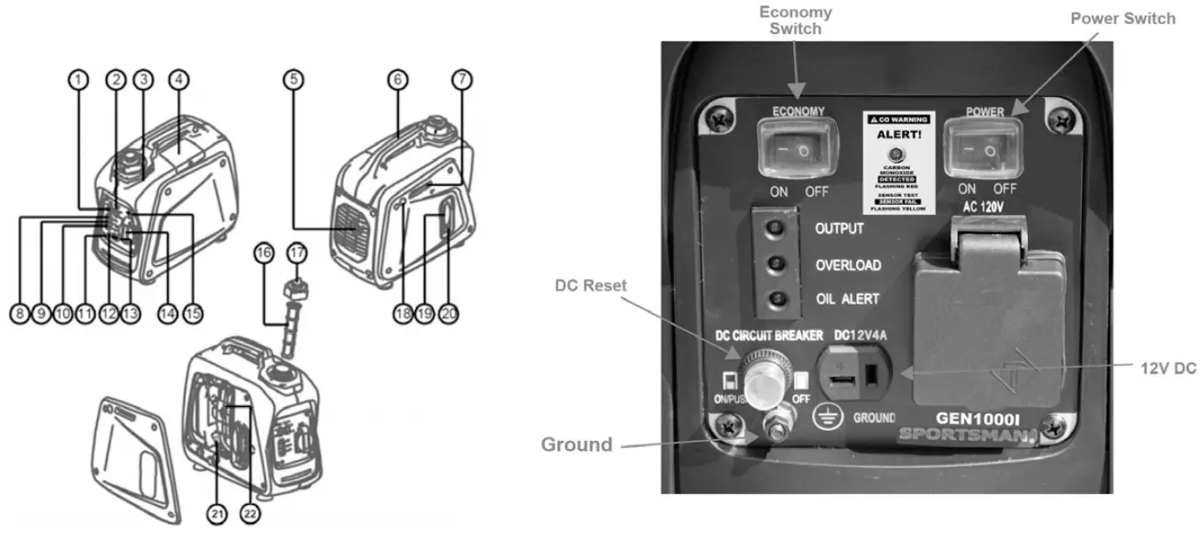
| (1) Economy control switch (4) Spark plug (7) Choke lever (10) Oil warning light (13) DC receptacle (16) Fuel filter (19) Recoil starter (22) Air filter cover | (2) Engine switch (5) Muffler (8) AC pilot light (11) Ground (earth) terminal (14) AC receptacle (17) Fuel tank cap (20) Fuel cock | (3) Fuel tank (6) Carrying handle (9) Overload indicator light (12) DC protector (18) Fuel pump (21) Oil filler cap |
 This is a Gasoline Powered Invertor Generator that offers clean power for electronics.
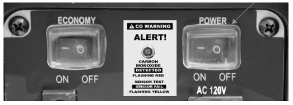
- ENGINE SWITCH
The engine switch controls the ignition system.
To Start generator, turn POWER switch ON. Then the engine can be started by sliding Choke lever to CHOKE then pull Recoil. Allow engine to run for a few seconds
then slide the Choke Lever to OFF. To Stop generator, press POWER switch to STOP. The engine will not run.
 - ECONOMY CONTROL SWITCH
When the economy control switch is turned “ON”, the economy control unit controls the engine speed according to the connected load. The results are better fuel connection and less noise. (Turn OFF when using less voltage.) - LOW OIL ALERT SENSOR
When the oil level falls below the acceptable level, the engine stops automatically. Unless you refill with oil, the engine will not start again. - OVERLOAD INDICATOR LIGHT
• The overload indicator light flickers when an overload of a connected electrical device is detected. This situation shall not be kept for a long time and it just needs to decrease the loads to its normal range and the overload indicator light will go off. When it is detected the inverter unit overheats, or the AC output voltage decreases, the overload indicator light will come on and the electronic breaker will then activate, stopping power to the generation in order to protect the generator and any connected electric devices. The output pilot light (Green) will be off, the overload indicator light will turn RED, & the engine will stop. It is needed to process as follows:
(a) Turn off any connected electric devices
(b) Reduce the total wattage of connected electric.
(c) Check for blockages in the cooling air inlet, muffler air exhaust pipe opening and the control unit & restart engine.
The generator AC output automatically resets when the engine is stopped and then restarted. The overload indicator light may come on for a few seconds at first when using electric devices that require a large starting current, such as a compressor or a submergible pump. However, this is not a malfunction. - DC CIRCUIT PROTECTOR
The DC circuit protector turns off automatically when the load exceeds the generator rated output. Reduce the load to within specified generator rated output if the DC circuit protector turns off. - FUEL COCK
The fuel cock is used to supply fuel from the tank to the carburetor.
Turn ON when getting ready to start the generator. Turn OFF when finished using the generator.
 To Stop generator, press POWER switch to STOP. The engine will not run.
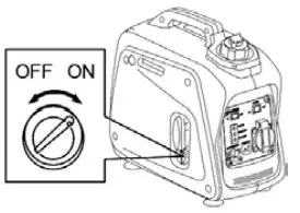
CHECK ENGINE FUEL
- Make sure there is sufficient fuel in the tank.
- If fuel is low, refill with unleaded automotive gasoline.
- Be sure to use the fuel filter screen on the fuel filter neck.
- Recommended fuel: Unleaded gasoline.
- Fuel tank capacity: 0.55 Gallon
- Do not refill tank while engine is running or hot.
- Close fuel cock before refueling with fuel.
- Be careful not to admit dust, dirt, water or other foreign objects into fuel.
- Do not fill above the top of the fuel filter or it may overflow when the fuel heats up later and expands.
- Keep open flames away.

CHECK ENGINE OIL
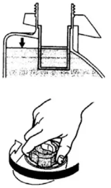
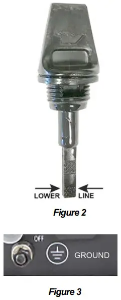
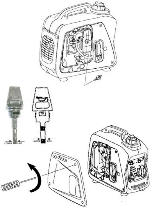
Remove side panel, remove oil filler cap and check the oil level. Make sure the oil is at top of Lower Level line (See Figure 2).
- WARNING: The generator has been shipped without engine oil. Fill with oil or it will not start.
- Do not tilt the generator when adding engine oil. This could result in overfilling and damage to the engine
- If oil level is below the lower line, add oil to top of Lower Level line. Screw in the oil filler cap when checking oil level.
- Oil Type: SAE 10W30 Oil capacity: 7.5 ounces
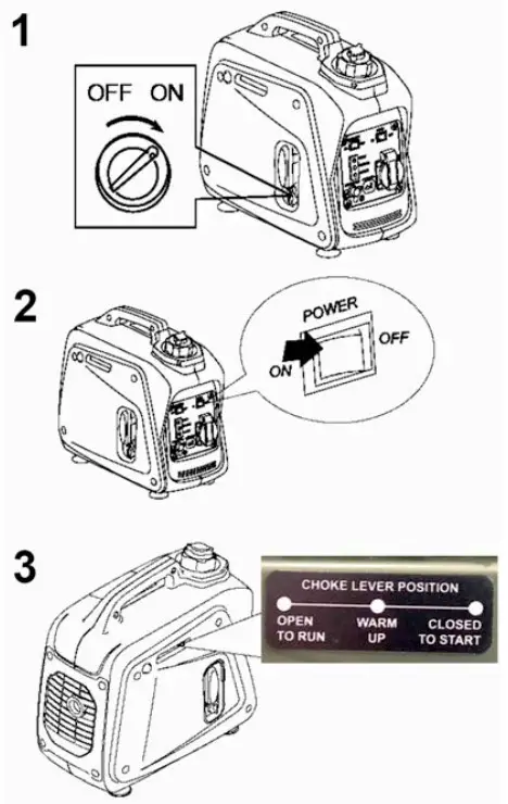
 The Grounding Terminal is located on the front of the generator, to the right of the AC Output socket.
GROUND
Ground this generator by tightening the grounding nut against a grounding wire. (See Figure 3) Use a No. 12 AWG (American Wire Gauge) stranded copper wire, which is generally considered an acceptable grounding wire. The other end of this grounding wire should be connected to a copper or brass grounding rod that is driven into the earth. Proper grounding of the generator will help prevent electrical shock in the event of a ground fault condition in the generator or in connected electrical devices. Proper grounding also helps dissipate static electricity, which often builds up in ungrounded devices.
STARTING THE ENGINE
- Before starting the engine, do not connect electric apparatus.
1. Turn the fuel cock lever to the “ON” position.
2. Turn the fuel tank cap air vent knob clockwise to the “OPEN” position. Turn the engine switch to the “ON” or “RUN” position.
3. Turn the choke lever to the “Closed To Start” position.
4. PUMP the PRIMER button until the glass bowl is full.
5. Pull the recoil starter handle slowly until resistance is felt. This is the “Compression” point. Return the handle to its original position and pull swiftly. Do not fully pull out the rope. After starting, allow the starter handle to return to its original position while still holding the handle. Grasp the handle firmly to prevent the generator from falling over when pulling the recoil starter.
6. Warm up the engine without a load for a few minutes.
7. Turn the choke lever to OPEN TO RUN position, then plug in appliances.
USING ELECTRIC POWER
AC APPLICATION
(a) Turn off switch(es) of the electrical appliance(s) before connecting the generator.
(b) Insert the plug(s) of the electrical appliance(s) into the receptacle.
- Be sure the electric apparatus is turned off before plugging in.
- Be sure the total load is within generator rated output.
- Be sure the socket load current is within socket rated current.
The economy control switch must be turned to “OFF” when using electric devices that require a large starting current, such as a compressor or a submergible pump.
DC APPLICATION
This usage is applicable to 12V battery charging.
Be sure the Economy Control Switch is turned off while charging the battery.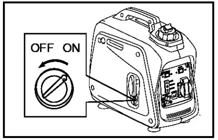
STOPPING THE ENGINE
Turn off the power switch of the electric apparatus or disconnect any electric devices.
Turn the POWER switch to “STOP” position.
Turn the fuel cock lever to “OFF”.
Turn the fuel tank cap air vent knob counterclockwise to the “CLOSED” position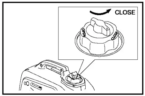
PERIODIC MAINTENANCE
MAINTENANCE CHART
Regular maintenance is important for the best performance and safe operation.
| Item | Remarks | Pre-operation check (daily) | Initial 1 months or 20 Hr | Every 3 months or 50Hr | Every 6 months or100Hr | Every 12 months or 300Hr |
| Spark Plug | Check condition adjust gap and clean. Replace if necessary. | |||||
| Engine Oil | Check oil level | |||||
| Replace | ||||||
| Oil filter | Clean oil filter | |||||
| Air Filter | Clean. Replace if necessary. | |||||
| Fuel Filter | Clean fuel cock filter. Replace if necessary | |||||
| Choke | Check choke operation | |||||
| Valve Clearance | Check and adjust when engine is cold. | |||||
| Fuel Line | Check fuel hose for crack or damage. Replace if |
| necessary. | ||||||
| Exhaust System | Check for leakage. Retighten or replace gasket if necessary | |||||
| Check muffler screen. Clean / replace if necessary. | ||||||
| Carburetor | Check choke operation | |||||
| Cooling system | Check fan damage. | |||||
| Starting system | Check recoil starter operation. | |||||
| Idle speed | Check and adjust engine idle speed | |||||
| Fittings / Fasteners | Check all fittings and fasteners correct if necessary. | |||||
| Crankcase breather | Check breather hose for cracks or damage. Replace if necessary | |||||
| Generator | Check the pilot light comes on |
ENGINE OIL REPLACEMENT
- Place the machine on a level surface and warm up the engine for several minutes.
Then stop the engine and turn the fuel cock knob to “OFF”.
Turn the fuel tank cap air vent knob clockwise. - Loosen the screws and remove the cover.
- Remove the oil filler cap
- Place an oil pan under the engine.
Tilt the generator to drain the oil completely - Place the generator on a level surface.
- Add engine oil to the Lower Level line.
- Install the oil filler cap
- Install the cover and tighten the screw
• Engine Oil SAE 10W30 Capacity: 7.5 oz.
• Be sure no foreign material enters the crankcase.
• Do not tilt the generator when adding engine oil. This could result in overfilling and damage to the engine
• Clean the oil filter every other 100 hr.
WASHABLE AIR FILTER
Maintaining an air cleaner in proper condition is very important. Dirt induced through improperly installed, improperly serviced, or inadequate elements damages and wears out engines. Keep the element always clean.
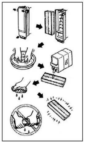
- Remove the cover.
- Remove the air filter cover and element.
- Wash the element in solvent and dry.
- Oil the element and squeeze out excess oil. The element should be wet but not dripping.
- Insert the element into the air filter.
- Install the cover.
The engine should never run without the Filter; excessive piston and/or cylinder wear may result.
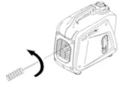
CLEANING AND ADJUSTING SPARK PLUG
- Remove the cover.
- Check for discoloration and remove the carbon.
- Check the spark plug type and gap.
Standard Spark Plug: CMR6A in) - Install the cover
FUEL TANK FILTER
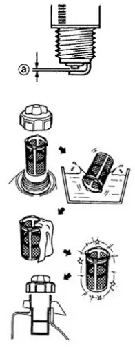
- Remove the fuel tank cap and filter.
- Clean the filter with solvent. If damaged, replace.
- Wipe the filter and insert it.
Be sure the tank cap is tightened securely.
Spark Plug Gap: 0.6-0.7 mm (0.024-0.028 - Install the spark plug.

MUFFLER SCREEN
- The engine and muffler will be very hot after the engine has been run.
- Avoid touching the engine and muffler while they are still hot with any part of your body or clothing during inspection or repai
1. Remove the cover. 2. Remove the muffler screen.
3. Use the flathead screw driver to pry the spark arrester out from the muffler
4. Remove the carbon deposits on the muffler screen and spark arrester using a wire brush.
5. Install the muffler screen.
6. Install the cover
 2. Remove the muffler screen.
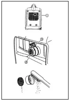
TROUBLESHOOTING
Engine won’t start
- Fuel system: No fuel supplied to combustion chamber.
• No fuel in tank …. Add fuel.
• Fuel in tank …. Fuel tank cap air vent knob to “OPEN”, fuel cock knob to “OPEN”.
• Clogged fuel line …. Clean fuel line.
• Clogged carburetor …. Clean carburetor.
Engine oil system
• Oil level is low…. Add engine oil.
Electrical systems – Poor spark
• Spark plug dirty with carbon or wet…. Remove carbon or wipe spark plug dry.
• Faulty ignition system…. Consult dealer.
Compression insufficient
• Worn out piston and cylinder….Consult dealer.
Generator won’t produce power
Safety device (AC) to “OFF” … Stop the engine, then restart.
Safety device (DC) to “OFF” … Press to reset the DC protector
STORAGE
Long term storage of your machine will require some preventive procedures to guard against deterioration.
- DRAIN THE FUEL
1. Remove the fuel tank cap, drain the fuel from the fuel tank.
2. Remove the cover, drain fuel from the carburetor by loosening the carb hose. - ENGINE
1. Remove the spark plug, pour in about one tablespoon of SAE 10W30 motor oil into the spark plug hole, reinstall the spark plug.
2. Use the recoil starter to turn the engine over several times (with ignition off).
3. Pull the recoil starter until you feel compression. Stop pulling.
4. Clean exterior of the generator and apply a rust inhibitor.
5. Store the generator in a dry, well-ventilated place, with the cover place over it.
6. The generator must remain in a vertical position.
SPECIFICATION
| MODEL | GEN1000I | ||
| GENERATOR | Type | Invertor Generator | |
| AC Voltage | |||
| 60Hz | 120V | ||
| Max. Output | 1.00 kVA | ||
| Rated Output | 0.80 kVA | ||
| Power Factor | 1.0 | ||
| DC Output | 12V / 4.0A | ||
| ENGINE | Model | XY139F-6 | |
| Type | Air-cooled, 4 cycle, OHV, Gasoline Engine | ||
| Bore×Stroke mm×mm | 39×33.5 | ||
| Displacement | 40 cc | ||
| Max. Output | 0.9KW / 5500rpm | ||
| Fuel | Regular Automobile Gasoline | ||
| Fuel tank Capacity | 0.55 Gallon | ||
| Rated Continuous Operation | 6.3 hr @ 50% load | ||
| Lubricating oil | SAE 10W30 | ||
| Lubricating oil Capacity | 7.5 ounce | ||
| Starting System | Recoil Starter | ||
| Ignition system | C.D.I. | ||
| Spark Plug: Type | CMR6A(TORCH) | ||
| DIMENSION | Net dimension L×W×H | 395×209×355 | |
| Overall dimension L×W×H | 425×230×380 | ||
| Net Weight | 9.2 Kg | ||
| Gross Weight | 11.4Kg | ||
- Specifications subject to change without prior notice.
- High Altitude Use: This generator is not recommended for high altitude use above 3,000 feet.
ENGINE BREAK-IN PROCEDURE
You can avoid small engine problems if you follow the break-in procedure below. Because the pistons and rings wear into the engine’s walls, small pieces of metal can flake off into the oil. It’s important to flush these pieces out of your generator by frequently changing the oil. Maintain at least a 50-75 percent load on your generator for the first 20 hours. (Do not operate the engine at full load during the first 20 hours of operation.) Varying the load will help seat the rings.
- Allow the engine to run for 5 minutes before adding any load.
- Change the break-in oil within the first 5 hours of use
- Do not operate the engine at full load during the first 20 hours of operation.
- Read and follow the Maintenance/Care section of this Generator manual.
STORAGE INSTRUCTIONS
Long term storage of your machine will require some preventive procedures to guard against deterioration.
- DRAIN THE FUEL
Remove the fuel tank cap, drain the fuel from the fuel tank - ENGINE
Remove spark plug, pour in about one tablespoon of SAE 10W30 motor oil into the spark plug hole and reinstall spark plug. Use the recoil starter to turn the engine over several times (with ignition off).
Pull the recoil starter until you feel compression.
Stop pulling.
Clean exterior of the generator and apply a rust inhibitor.
Store the generator in a dry, well-ventilated place, with the cover place over it.
The generator must remain in a vertical position
WIRING DIAGRAM
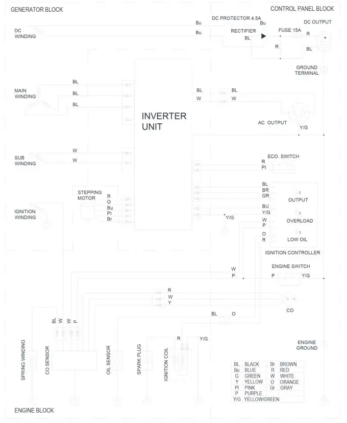
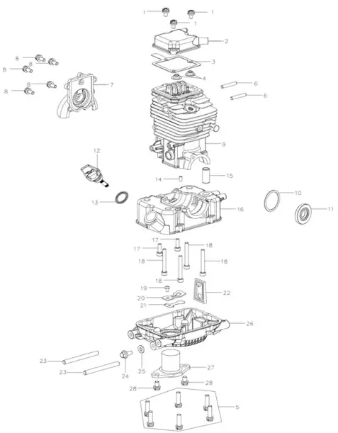 FIG.A CRANKCASE ASSY
| No. | Part No. | Qty | |
| 1 | 301060076 | Screw M5x20 | 3 |
| 2 | 2147630017 | Cylinder Head Cover | 1 |
| 3 | 2147630016 | Cylinder Head Cover Seal | 1 |
| 4 | 2147620001 | Valve Oil Seal | 2 |
| 5 | 301060077 | Dual-Head Bolts M5x25 | 6 |
| 6 | 2147630019 | Dual-Head Bolts M5x28 | 2 |
| 7 | 2147630018 | Cam Chamber Cover | 1 |
| 8 | 301060074 | Screw M5x14 | 5 |
| 9 | 2148320010 | Upper Crankcase | 1 |
| 10 | 2147730001 | Washer 30x37x1 | 1 |
| 11 | 303010033 | Oil Seal 15x35x5 | 1 |
| 12 | 2146130067 | Oil Gauge | 1 |
| 13 | 2147630008 | Oil Gauge Gasket | 1 |
| 14 | 301110007 | Dowel Pin 4×8 | 1 |
| 15 | 2147630010 | Ventilation Nozzle | 1 |
| 16 | 2148330011 | Lower Crankcase | 1 |
| 17 | 301030840 | Screw M5x16 | 2 |
| 18 | 301030272 | Screw M5x40 | 4 |
| 19 | 301060415 | Countersunk Head Screw Max | 1 |
| 20 | 2147630046 | Limiting Board | 1 |
| 21 | 2154230020 | Valve Plate | 1 |
| 22 | 2148320011 | One-Way Valve Components | 1 |
| 23 | 2147630015 | Dual-Head Bolts M6x36 | 2 |
| 24 | 301010476 | Hexagon Flange Bolt M6x12 | 1 |
| 25 | 2147630014 | Aluminium Gasket 6x13x2 | 1 |
| 26 | 2147630011 | Oil Pan | 1 |
| 27 | 2147630012 | Oil Level Sensor | 1 |
| 28 | 301060368 | Screw M6x18 | 2 |
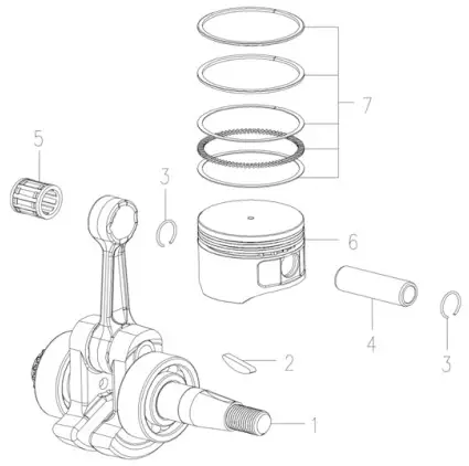 FIG.B CRANKCASE ASSY
| No. | Part No. | Qty | |
| 1 | 2147620006 | Connecting Rod | 1 |
| 2 | 2147630028 | Woodruff Key | 1 |
| 3 | 2147630027 | Piston Pin Clip | 2 |
| 4 | 2147630026 | Piston Pin | 1 |
| 5 | 302020088 | Needle Bearing K101414 | 1 |
| 6 | 2148130003 | Piston | 1 |
| 7 | 2148320006 | Piston Ring | 1 |
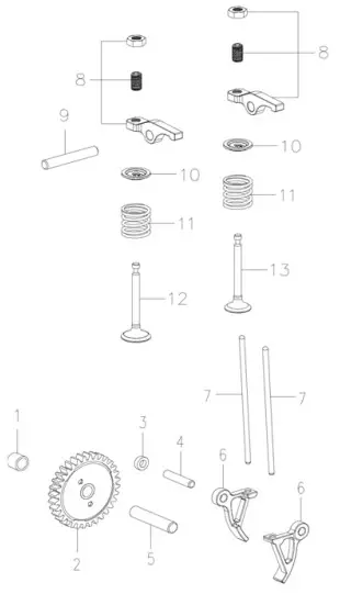 FIG C. CAMSHAFT
| No. | Part No. | Qty | |
| 1 | 2147630020 | Dowel Bush | 1 |
| 2 | 2147620030 2147630034 2147630035 2147630036 | Camshaft Decompression of the pin Torsional spring Cover for cam | 1 1 1 1 |
| 3 | 2147630038 | Rocker Gasket | 1 |
| 4 | 301110265 | Pin4 g4x20 | 1 |
| 5 | 301110267 | Pin4 g6x30 | 1 |
| 6 | 2147630037 | Lower Rocker | 2 |
| 7 | 2147630039 | Tappet | 2 |
| 8 | 2147630031 | Upper Rocker | 2 |
| 9 | 301110266 | Pin 5 g5x32 | 1 |
| 10 | 2147630042 | Valve Spring Seat | 2 |
| 11 | 2147630041 | Valve Spring | 2 |
| 12 | 2148330012 | Intake Valve | 1 |
| 13 | 2148330013 | Exhaust Valve | 1 |
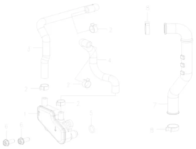 FIG D.LUBRICATION SYSTEM
| No. | Part No. | Qty | |
| 1 | 2147620009 | Deaerator | 1 |
| 2 | 401040002 | Pipe Hoop 9 | 4 |
| 3 | 2147630053 | Respiratory Tube | 1 |
| 4 | 2147630054 | Outlet Tube | 1 |
| 5 | 2147630055 | O Ring | 1 |
| 6 | 301010003 | Hexagon Flange Bolt M5x16 | 2 |
| 7 | 2147630052 | Upper Oil Pipe | 1 |
| 8 | 401040001 | Pipe Hoop 13 | 2 |
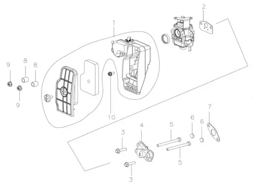 FIG E. AIR CLEANER
| No. | Part No. | Qty | |
| 1 | 2147630058 2147630063 2147630064 | Air Filter Foam big head chrome plated Screw | 1 1 1 |
| 2 | 2147630057 | Gasket of Carburator | 1 |
| 3 | 301010688 | Hexagon Flange Bolts M5x22 | 2 |
| 4 | 2148120003 | Insulation Board Components | 1 |
| 5 | 301010749 | Hexagon Flange Bolts M5x53 | 2 |
| 6 | 2148130008 | Block rubber | 2 |
| 7 | 2147630056 | Insulation Board Gasket | 1 |
| 8 | 15561100004002 | Fan Volute Bush | 2 |
| 9 | 301020249 | Hexagon Flange Bolts M5 | 2 |
| 10 | 301050243 | Tap Screw ST4.8×16-F.H | 1 |
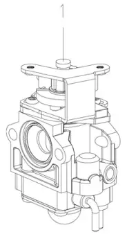 FIG.F CARBURETOR
| No. | Part No. | Qty | |
| 1 | 2147620022 | Carburator | 1 |
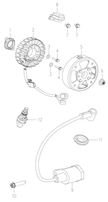 FIG I. GENRATOR
| No. | Part No. | Qty | |
| 1 | 2147630086 | Locating Plate | 1 |
| 2 | 2148720012 | Stator 0.8KW 420V 580Hz | 1 |
| 3 | 2147630132 | Washer 5 | 1 |
| 4 | 301010688 | Hexagon Flange Bolts M5x22 | 2 |
| 5 | 2147620018 | Rotor | 1 |
| 6 | 301020111 | Hexagon Flange Nut M10x | 1 |
| 7 | 301010001 | Hexagon Flange Bolts M5x10 | 2 |
| 8 | 2147630135 | Trigger | 1 |
| 9 | 2147620019 | Ignition Coil | 1 |
| 10 | 301050246 | Tap Screw ST4.8×25-F.H | 1 |
| 11 | 2147630096 | Ignition Coil Cap Seal | 1 |
| 12 | 403240002 | Spark Plug CMR6A | 1 |
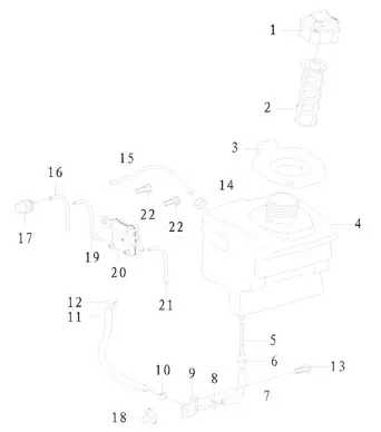 FIG J. FUEL TANK (EPA)
| No. | Part No. | Description | Qty |
| 1 | 2462420008 | Fuel Tank Cap Assy. | 1 |
| 2 | 2462420009 | Fuel Tank Filter | 1 |
| 3 | 2460730008 | Fuel Tank Port Rubber | 1 |
| 4 | 2460730026 | Fuel Tank (EPA) | 1 |
| 5 | 2462420013 | Fuel Outlet Filter | 1 |
| 6 | 401040007 | Steel Wire Clamp 011 | 1 |
| 7 | 2460730028 | Fuel Hose(EPA) | 1 |
| 8 | 401040006 | Steel Wire Clamp 010 | 1 |
| 9 | 2460720003 | Fuel Cock | 1 |
| 10 | 401040002 | Steel Wire Clamp 09 | 1 |
| 11 | 2460730027 | Fuel Hose 4.5×7.5×180(EPA) | 1 |
| 12 | 401040003 | Steel Wire Clamp 08 | 1 |
| 13 | 301050280 | Tap Screw GB/T845 ST4.8×13-F | 1 |
| 14 | 2460730016 | Fuel-hole Plug | 1 |
| 15 | 2460730034 | Fuel Hose 2.5x5x130(EPA) | 1 |
| 16 | 2460730035 | Fuel Hose 2.5x5x85(EPA) | 1 |
| 17 | 2460720004 | Fuel Lubricator | 1 |
| 18 | 2460730017 | Fuel Cock Knob | 1 |
| 19 | 2460730036 | Fuel Hose 2.5x5x95(EPA) | 1 |
| 20 | 2460720005 | negative pressure pump | 1 |
| 21 | 2460730033 | Fuel Hose 2.5x5x120(EPA) | 1 |
| 22 | 301050069 | Tap Screw GB/T845 ST4.8×9.5-F | 2 |
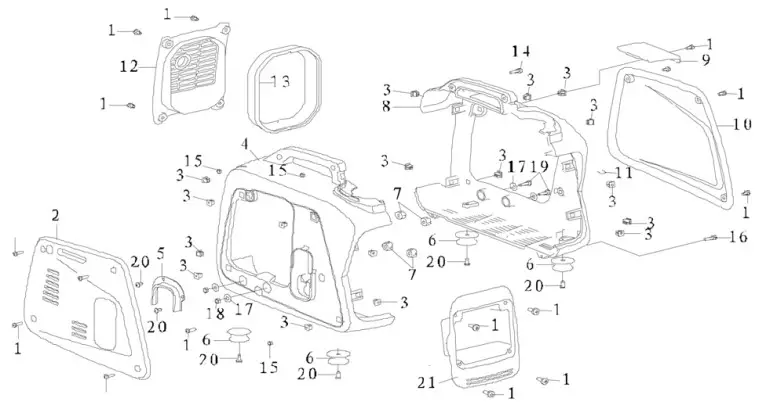 FIG K. SHELL
| No. | Part No. | Description | Qty |
| 1 | 301050280 | Screw 4.8×13-F | 18 |
| 2 | 2460730091 | Right Side Cover | 1 |
| 3 | 2460730011 | Fastener | 17 |
| 4 | 2460730004 | Right Cover of Shell | 1 |
| 5 | 2460730006 | Edge Protection | 1 |
| 6 | 2460720001 | Vibration Absorber | 4 |
| 7 | 2460730013 | Rubber Pad c1)6x016x10 | 4 |
| 8 | 2460730001 | Left Cover of Shell | 1 |
| 9 | 2460730003 | Upper Cover | 1 |
| 10 | 2460730090 | Left Side Cover | 1 |
| 11 | 2461530007 | Clamp | 1 |
| 12 | 2460730009 | Muffler Cover | 1 |
| 13 | 2460730010 | Muffler Cover Seal | 1 |
| 14 | 301030847 | Screw GB/T9074.4 M5x18 | 2 |
| 15 | 301020257 | Hexagon Nut M5 | 4 |
| 16 | 301030849 | Cross Pan Head Screw M5x16 | 2 |
| 17 | 2460730014 | Rubber Pad 06.5×1)16×2 | 4 |
| 18 | 301020159 | Lock Nut GB/T6187 M6 | 4 |
| 19 | 301010748 | Hexagon Flange Bolts M6x25 | 2 |
| 20 | 301050069 | Tap Screw GB/T845 ST4.8×9.5-F | 6 |
| 21 | 2460730007 | Panel Box | 1 |
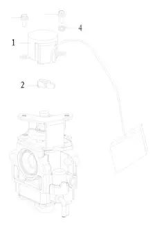 FIG L. GOVERNOR
| No. | Part No. | Description | Qty |
| 1 | 2460720017 | Stepper Motor | 1 |
| 2 | 2155630001 | Drive Arm | 1 |
| 3 | 301060375 | Screw M4 x6 | 2 |
| 4 | 301080103 | Spring Washer 4 | 1 |
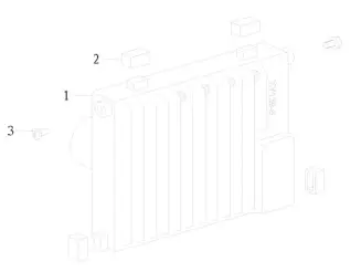 FIG M. INVERTER
| No. | Part No. | Description | Qty |
| 1 | 2460720039 | Inverter 0.7Kw 120V-60Hz | 1 |
| 2 | 2460730012 | Inverter Gasket | 4 |
| 3 | 301060018 | Screw GB/T9074.4 M5x 12 | 2 |
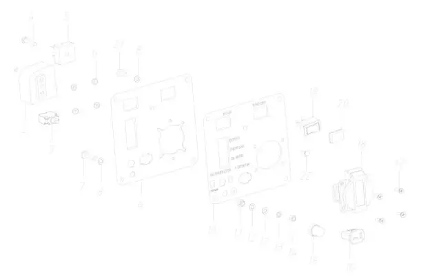 FIG N. CONTROL PANEL (FOR USA)
| No. | Part No. | Description | Qty |
| 1 | 301060020 | Cross Pan Head Screw M5x16 | 1 |
| 2 | 2462420015 | Ignition Control Module | 1 |
| 3 | 403210007 | Overload Protector 4.5A | 1 |
| 4 | 301060374 | Cross Pan Head Screw M5x16 | 1 |
| 5 | 402160003 | Rectifier KBPC3502 | 1 |
| 6 | 301020218 | Hexagon Flange Nut M4 | 4 |
| 7 | 301010468 | Flange Bolt GB/16674 M5x16 | 1 |
| 8 | 301080089 | Lock Gasket GB862.2 (p5 | 3 |
| 9 | 2460720006 | Panel Components | 1 |
| 10 | 54607105804016 | Panel Sticker | 1 |
| 11 | 301020219 | Hexagon Flange Nut M5 | 1 |
| 12 | 301080101 | Flat Washer GB/T97 (p5 | 2 |
| 13 | 301080046 | Spring Washer GB/T93 (p5 | 1 |
| 14 | 301020236 | Hexagon Nut GB/T6170 M5 | 1 |
| 15 | 403210004 | Water-Proof Cap of Protector | 1 |
| 16 | 403030073 | DC Charging Socket | 1 |
| 17 | 301030845 | Countersunk Head Screw M4x12 | 4 |
| 18 | 403030017 | American Socket 5-15R | 1 |
| 19 | 402150026 | Boat Switch | 2 |
| 20 | 402150010 | Water-Proof Cap of Boat Switch | 2 |
| 21 | 301060369 | Screw M5x8 | 2 |
| 22 | 403210188 | CO SENSOR ALARM | 1 |
EMISSION CONTROL SYSTEM WARRANTY
Buffalo Corp.
Your Warranty Rights and Obligations
The California Air Resources Board, The United States Environmental Protection Agency(US EPA) and Buffalo Corp. are pleased to explain the exhaust and evaporative emissions control system warranty on your 2022 model year small off-road engine. In California, new equipment that use small off-road engines must be designed, built, and equipped to meet the State’s stringent anti-smog standards. Buffalo Corp. must warrant the emissions control system on your small off-road engine for the periods of time listed below provided there has been no abuse, neglect or improper maintenance of your small off-road engine or equipment leading to the failure of the emissions control system.
Your emissions control system may include parts such as the carburetor or fuel-injection system, the ignition system, catalytic converter, fuel tanks, fuel lines (for liquid fuel and fuel vapors), fuel caps, valves, canisters, filters, clamps and other associated components. Also included may be hoses, belts, connectors, and other emission-related assemblies.
Where a warrantable condition exists, Buffalo Corp. will repair your small off-road engine at no cost to you including diagnosis, parts and labor.
Manufacturer’s Warranty Coverage
The exhaust and evaporative emissions control system on your small off-road engine is warranted for two years. If any emissions related part on your small off-road engine is
defective, the part will be repaired or replaced by Buffalo Corp.
Owner’s Warranty Responsibility
As the small off-road engine owner, you are responsible for the performance of the required maintenance listed in your owner’s manual. Buffalo Corp. recommends that you retain all receipts covering maintenance on your small off-road engine, but Buffalo Corp. cannot deny warranty coverage solely for the lack of receipts or for your failure to ensure the performance of all scheduled maintenance. As the small off-road engine owner, you should however be aware that Buffalo Corp. may deny you warranty coverage
if your small off-road engine or a part has failed due to abuse, neglect, or improper maintenance or unapproved modifications.
You are responsible for presenting your small off-road engine to a Buffalo Corp. distribution center or service center as soon as the problem exists. The warranty repairs shall be completed in a reasonable amount of time, not to exceed 30 days.
If you have any questions regarding your warranty rights and responsibilities, you should contact Buffalo Corp. customer service representative at 1-866-460-9436 or write to [email protected].
DEFECTS WARRANTY COVERAGE
Adopted by the Air Resources Board, Buffalo Corp. warrants to the ultimate purchaser and each subsequent purchaser that the small off-road engine (SORE)(1) has been designed, built and equipped so as to conform with all applicable regulations; and (2) is free from defects in materials and workmanship that cause the failure of a warranted part to conform with those regulations as may be applicable to the terms and conditions stated below.
The warranty period begins on the date the engine is delivered to an ultimate purchaser or first placed into service. The warranty period is two years.
Subject to certain conditions and exclusions as stated below, the warranty on emissions related parts is as follows:
Any warranted part that is not scheduled for replacement as required maintenance in your Owner’s Manual is warranted for the warranty period stated above. If the part fails during the period of warranty coverage, the part will be repaired or replaced by Buffalo Corp. according to Subsection (4) below. Any such part repaired or replaced under warranty will be warranted for the remainder of the periods.
Any warranted part that is scheduled only for regular inspection in your owner’s manual is warranted for the warranty period stated above. Any such part repaired or replaced under warranty will be warranted for the remaining warranty period.
Any warranted part that is scheduled for replacement as required maintenance in your owner’s manual is warranted for the period of time before the first scheduled replacement date for that part. If the part fails before the first scheduled replacement, the part will be repaired or replaced by Buffalo Corp. according to Subsection (4) below. Any such part repaired or replaced under warranty will be warranted for the remainder of the period prior to the first scheduled replacement point for the part.
Repair or replacement of any warranted part under the warranty provisions herein must be performed at a warranty station at no charge to the owner.
Notwithstanding the provisions herein, warranty services or repair will be provided at all of our distribution centers that are franchised to service the subject engines.
The engine owner must not be charged for diagnostic labor that leads to the determination that a warranted part is in fact defective, provided that such diagnostic work is performed at a warranty station.
Buffalo Corp. is liable for damages to other engine components proximately caused by a failure under warranty of any warranted part.
Throughout the engine warranty period stated above, Buffalo Corp. will maintain a supply of warranted part sufficient to meet the expected demand for such parts.
Any replacement may be used in the performance of any warranty maintenance or repairs and must be provided without charge to the owner. Such use will not reduce the warranty obligations of Buffalo Corp.
Add-on or modified parts that are not exempted by the Air Resources Board may not be used. The use of any non-exempted add-on or modified parts by the ultimate purchaser will be grounds for disallowing a warranty claims. Buffalo Corp. will not be liable to warrant failures of warranted parts caused by the use of a non-exempted add-on or modified part.
The manufacturer issuing the warranty shall provide any documents that describe that manufacturer’s warranty procedures or policies within five working days of request by the Air Resources Board.
EMISSION WARRANTY PARTS LIST
Fuel Metering System:
Gasoline carburetor assembly and its internal components
Carburetor gaskets
(c) fuel lines (for liquid fuel and fuel vapors)
(d) Clamps
(e) Fuel tank
(f) Fuel line fittings
(g) Pressure regulator (if equipped)
(h) Mixer assembly and its internal components (if equipped)
Air induction system including:
Intake pipe/manifold (b) Air cleaner
Ignition system including:
Spark plug (b) Ignition coil
Catalytic muffler assembly including:
Muffler gasket (b) Exhaust manifold
(c) Catalytic converter
Crankcase breather assembly including:
Breather connection tube
(6) Fuel tank evaporative emissions control system including:
(a) Purge valves (b) Fuel cap
Fuel tank (d) fuel lines (for liquid fuel and fuel vapors)
Miscellaneous items used in above systems including:
Switches (b) Hoses, belts connectors and assemblies
Air injection system
Pulse valve
Please Note:
For this warranty, Buffalo Corp. shall warrant the Evaporative and Exhaust combined emission control system on your products.
This generator features CO WARNING, which will automatically shut-off if dangerous levels of CO is detected.
FEATURES![]() CO WARNING
CO WARNING
ALERT!
Carbon monoxide (also known as CO) can be dangerous for humans and pets. Carbon monoxide poisoning can lead to death in a very short time. It is called “the silent killer” because it is odorless, tasteless and invisible: you may be exposed without knowing it.
This generator features CO WARNING. which will auto-matically shut-off if dangerous levels of CO is detected.![]() WARNING! IF DANGEROUS CARBON MONOXIDE LEVELS ARE DETECTED, ENGINE WILL SHUTOFF
WARNING! IF DANGEROUS CARBON MONOXIDE LEVELS ARE DETECTED, ENGINE WILL SHUTOFF![]() AUTOMATIC SHUTOFF – YOU
AUTOMATIC SHUTOFF – YOU
MUST:
MOVE GENERATOR TO AN OPEN, OUTDOOR AREA. POINT EXHAUST AWAY. DON’T RUN GENERATOR IN ENCLOSED AREAS (E.G. NOT IN HOUSE OR GARAGE)
The indicator will light RED and the engine will shutdown if dangerous CO levels are detected. The engine will not restart for 5 minutes. If an error in the carbon monoxide system is detected. the indicator will light YELLOW.![]() MOVE TO FRESH AIR AND GET MEDICAL HELP IF SICK, DIZZY OR WEAK.
MOVE TO FRESH AIR AND GET MEDICAL HELP IF SICK, DIZZY OR WEAK.
Carbon monoxide (also known as CO) can be dangerous for humans and pets. Carbon monoxide poisoning can lead to death in a very short time. It is called “the silent killer” because it is odorless, tasteless and invisible: you may be exposed without knowing it.
The CO Detection module monitors for the accumulation of poisonous CO gas found in engine exhaust when the generator is running. If CO detector detects increasing levels of CO gas, it automatically shuts off the engine. CO detector only monitors when the engine is running. Generators are intended to be used outdoors, far from occupied buildings and the exhaust pointed away from personnel and buildings. However, if misused and operated in a location that results in the accumulation of CO, like indoors or in a partially enclosed area, CO detector shuts off the engine, notifies the user of what has happened and directs the user to read the instruction action label for steps to take. CO detector is not a substitute for an indoor carbon monoxide alarm.
After a shut-off, a blinking RED light in the CO detector badge on the side of the generator provides notification that the generator was shut off due to an accumulating CO hazard. The RED light will blink for at least five minutes after a CO shut-off. Move the generator to an open, outdoor area and point the exhaust away from people and occupied buildings. Once relocated to a safe area, the generator can be restarted and the proper electrical connections made to supply electrical power. The RED light will stop blinking automatically upon engine re-start. Introduce fresh air and ventilate the location where the generator had shut down.
If a CO detector system fault has occurred and no longer provides protection, the portable generator is shut off automatically and the YELLOW light will blink for at least five minutes in the CO detector badge to notify the user of the fault. The CO detector module can only be diagnosed and repaired by a trained technician at the dealer. The generator can be restarted, but may continue to shut-off.![]() CO detector will detect the accumulation of Carbon Monoxide from other fuel burning sources such as engine powered tools or propane heaters used in the area of operation. For example, if another generator is used and the exhaust is pointed at a CO detector equipped generator, CO detector may initiate a shut-off due to rising CO levels. This is not an error. Hazardous Carbon Monoxide has been detected. The user must take action to move and re-direct these devices to better dissipate Carbon Monoxide far away from personnel and occupied buildings.
CO detector will detect the accumulation of Carbon Monoxide from other fuel burning sources such as engine powered tools or propane heaters used in the area of operation. For example, if another generator is used and the exhaust is pointed at a CO detector equipped generator, CO detector may initiate a shut-off due to rising CO levels. This is not an error. Hazardous Carbon Monoxide has been detected. The user must take action to move and re-direct these devices to better dissipate Carbon Monoxide far away from personnel and occupied buildings.
![]() 2022204
2022204


