![]() TROUBLESHOOTING GUIDE
TROUBLESHOOTING GUIDE
(for all Gen II units)
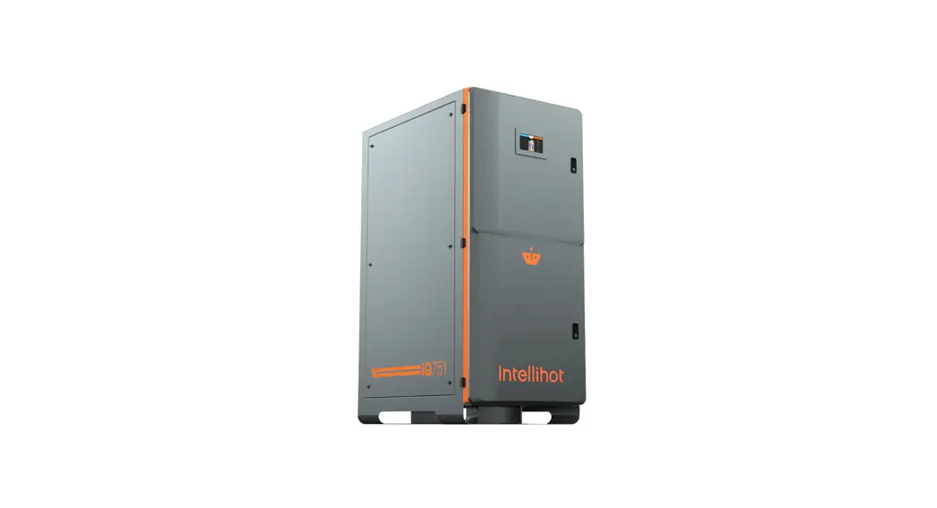
iQ751 Water Heater
This guide contains information for identifying and correcting any issues that may arise.
Product Support/Warranty
If the water heater requires additional service, please use one of the following options for contacting Intellihot Technical Support:
- Call: 309-473-8040 (toll-free 1-877-835-1705), press 1
- Email: [email protected]
When contacting Technical Support, please have the following information ready: - Model Number
- Serial Number
- Date Purchased/Installed
- Installation location & application
Suggested Tool List
- Digital Manometer
- Electrical Multimeter
- Flue Gas Analyzer (for NOx & CO2)
- 7mm Socket/Ratchet
- #1 & #2 Phillips Screwdrivers
- Instrument Flat Blade Screwdriver
- Pliers
- Adjustable Wrench
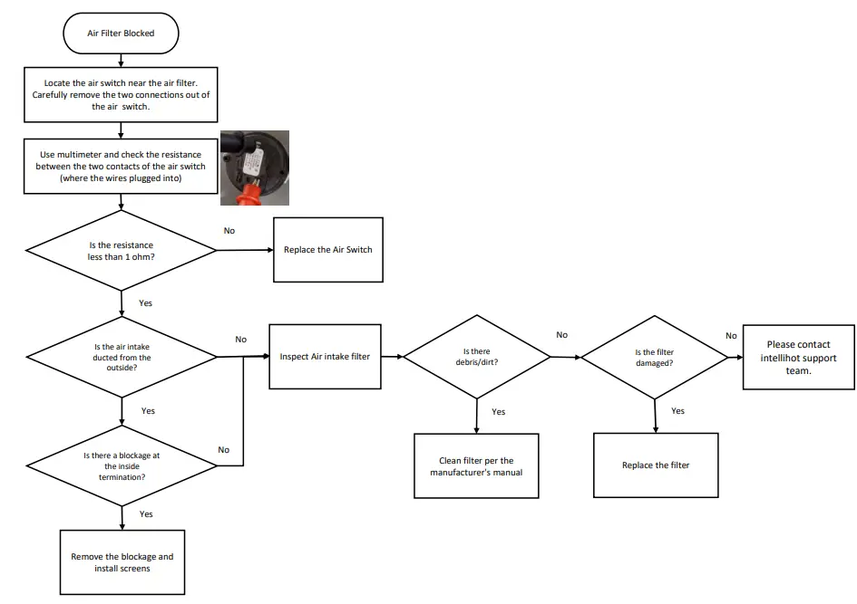
Air Filter Blocked Alert
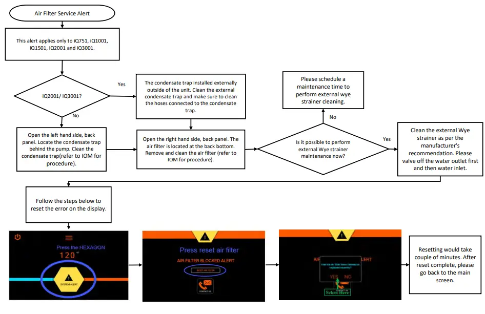
Air Filter Service Alert Maintenance Alert
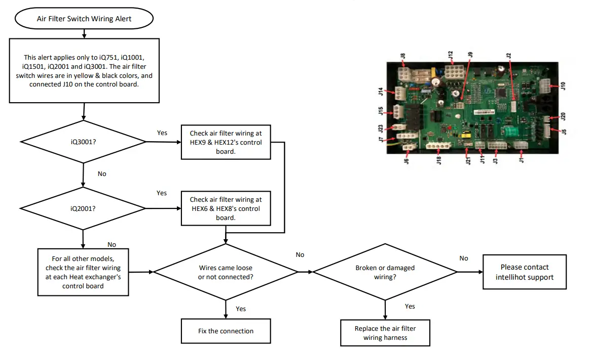
Air Filter Switch Wiring Alert
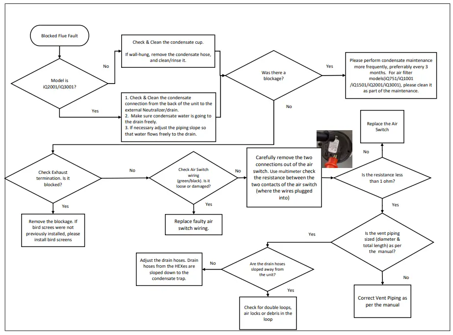
Blocked Flue Fault
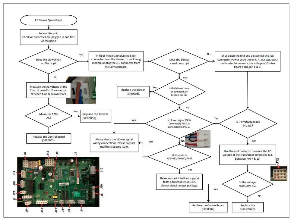
Blower Fault / Blower Speed Fault
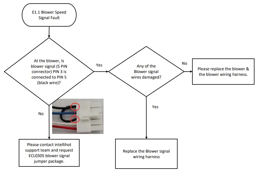
Blower Speed Signal Fault
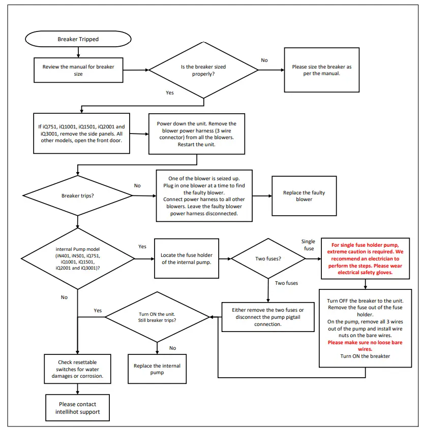
Breaker Tripped
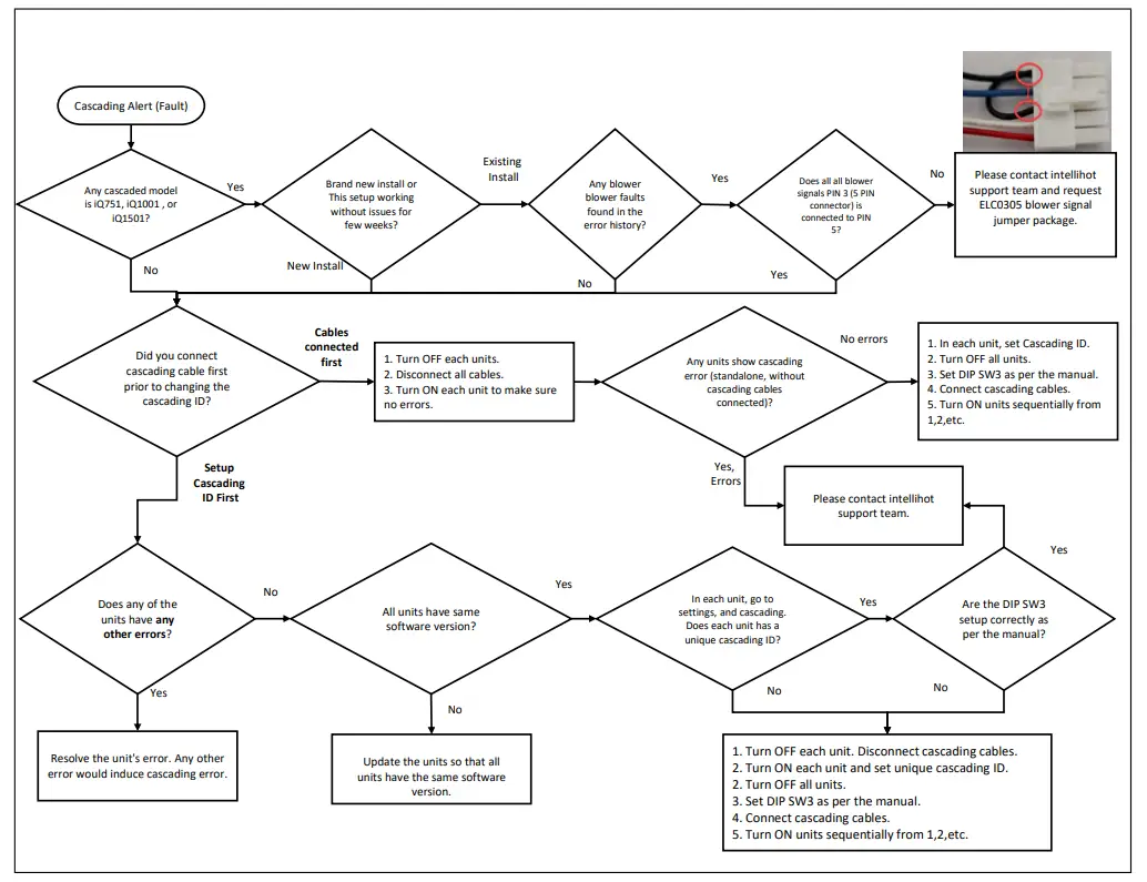
Cascading Alert (Fault)
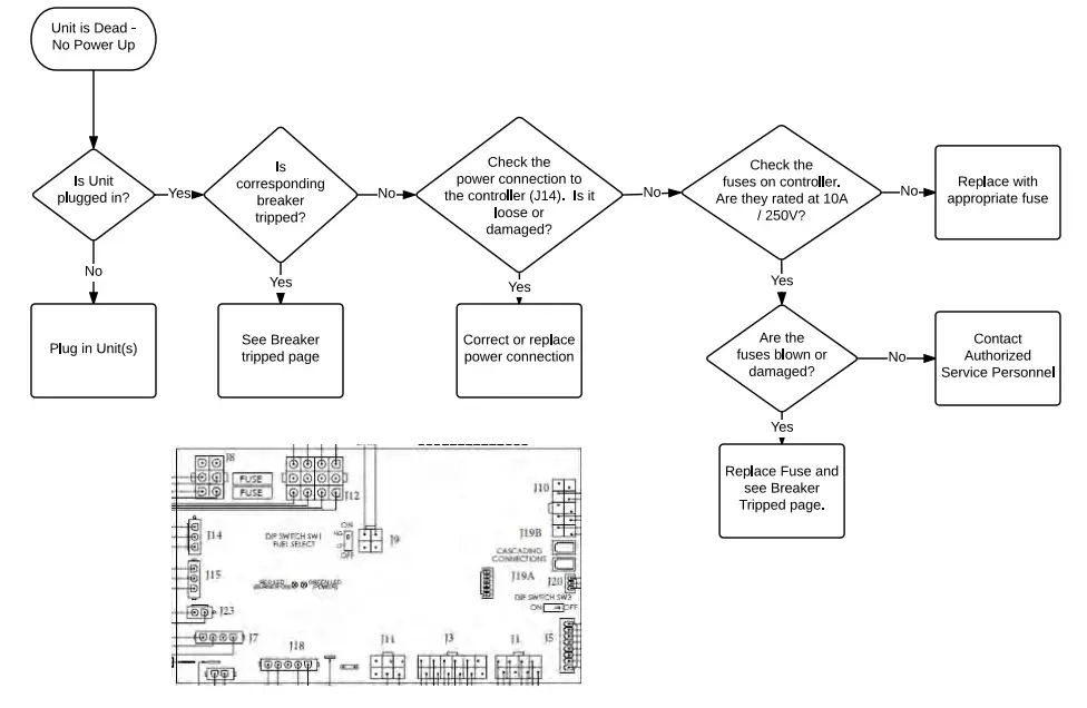
Dead Unit – No Power Up
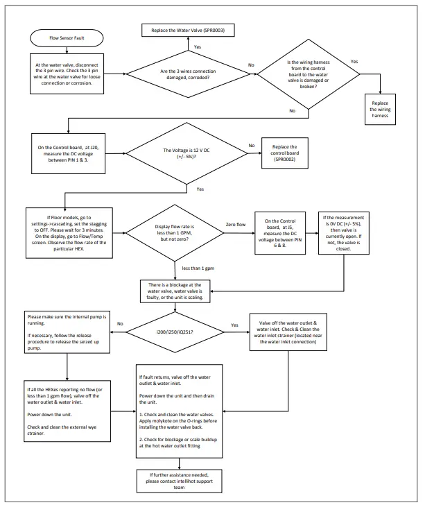
Flow Sensor Fault
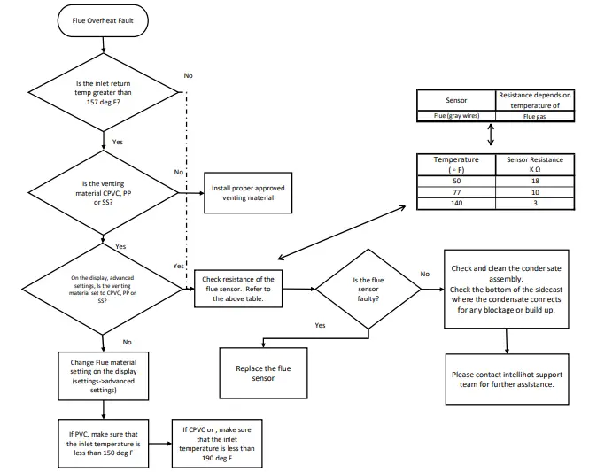
Flue Overheat Fault
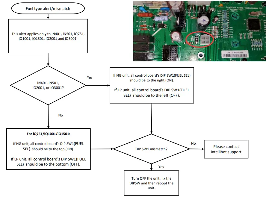
Fuel Type Alert Fuel Type Mismatch
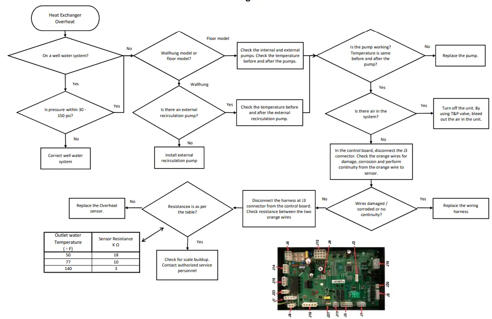
Heat Exchanger Overheat
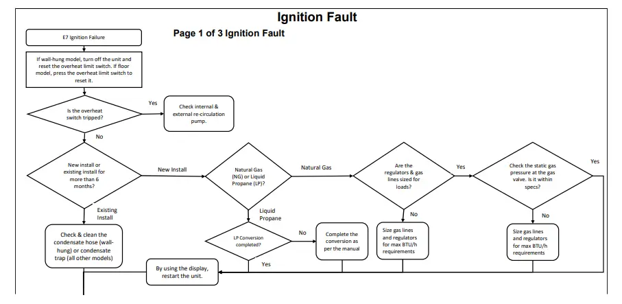
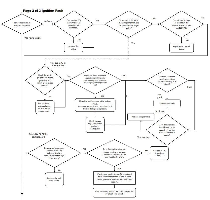
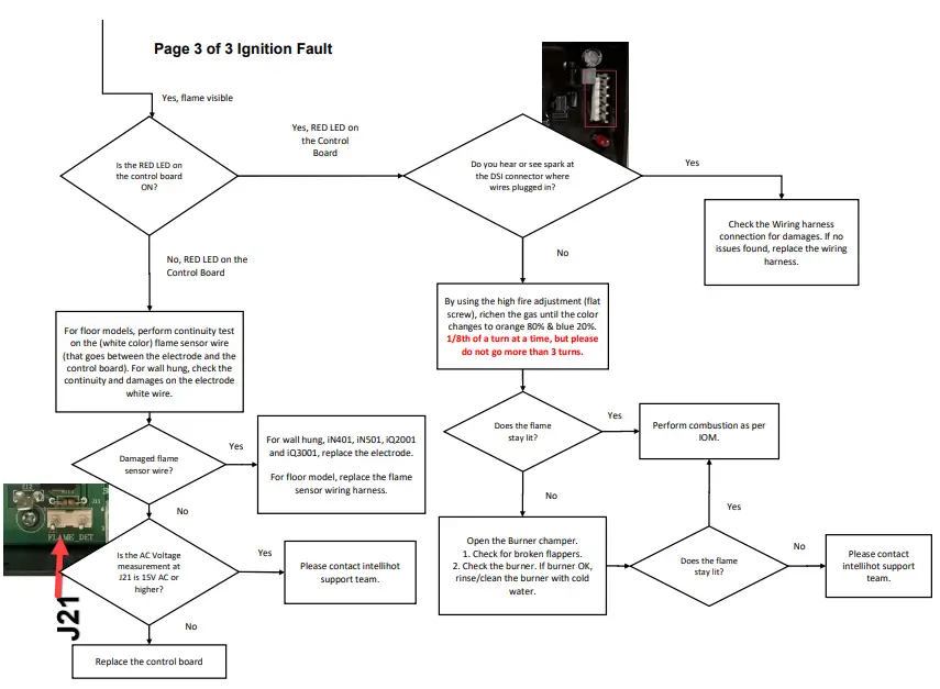
Ignition Fault
Page 1 of 3 Ignition Fault
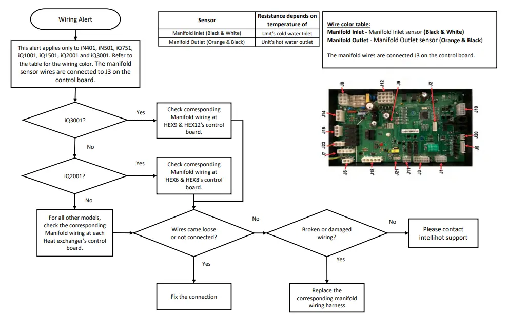
Manifold Inlet/Outlet Wiring Alert
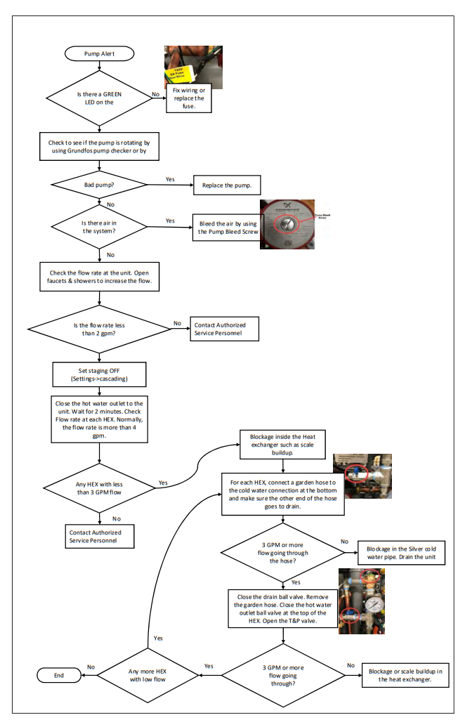
Pump Alert
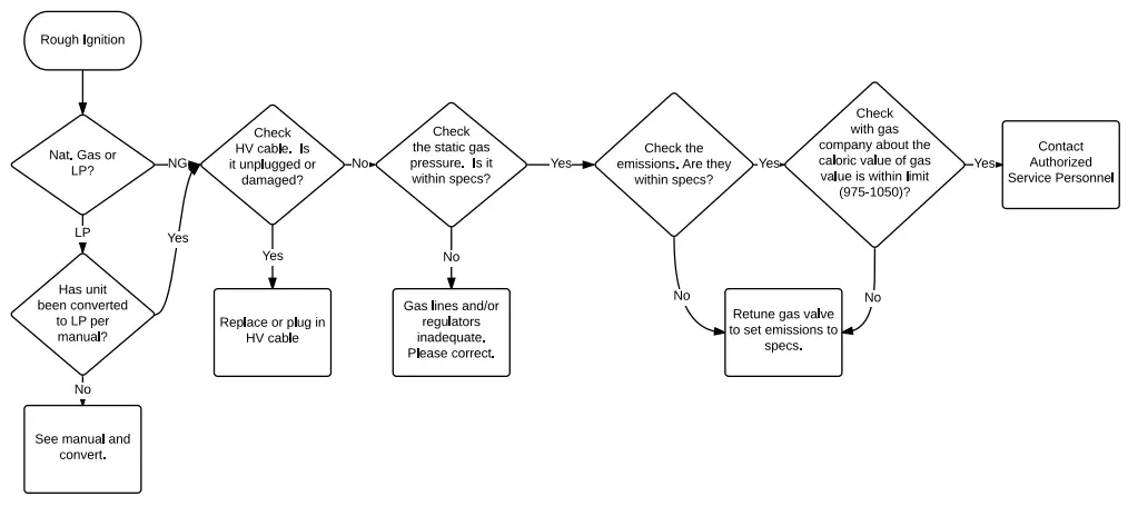
Rough Ignition
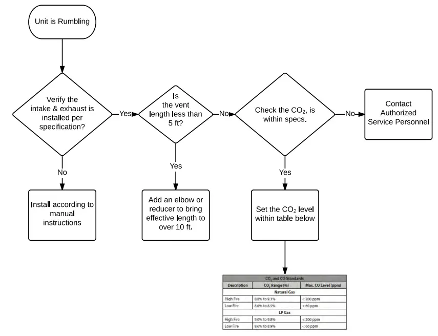
Rumbling
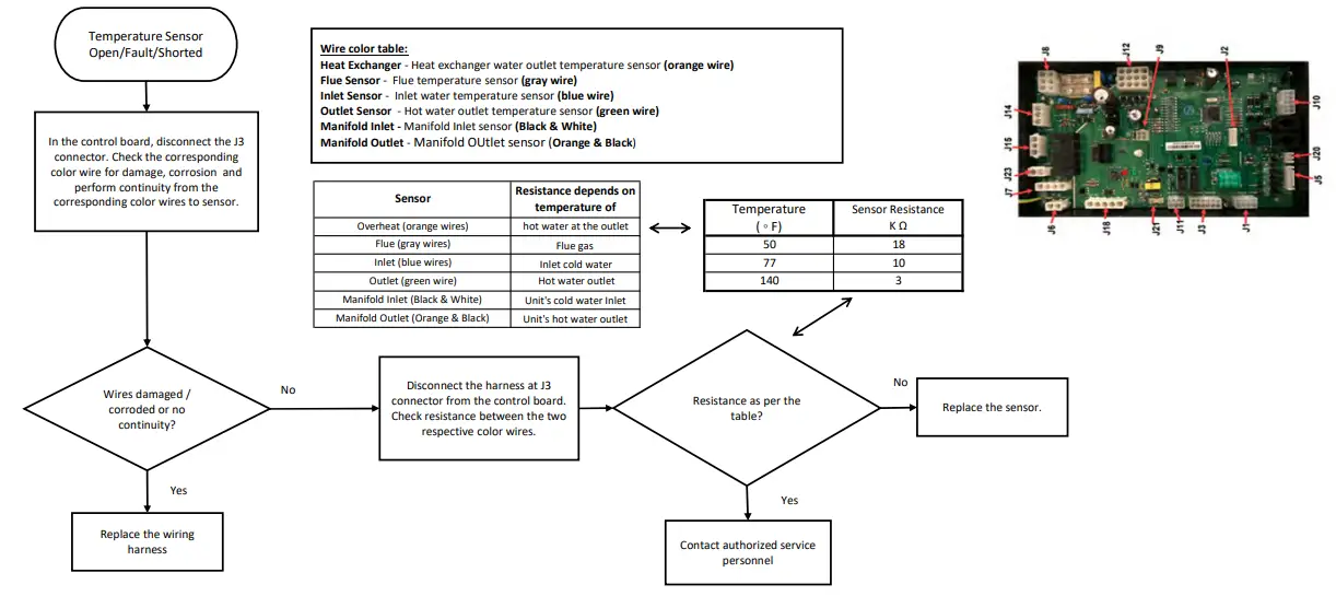
Inlet/Outlet/Heat Exchanger/Manifold Inlet/Manifold Outlet/Flue Sensor Open/Fault/Shorted
Water Valve Opening Fault
Water Valve Closing Fault
Water Valve Switch Fault
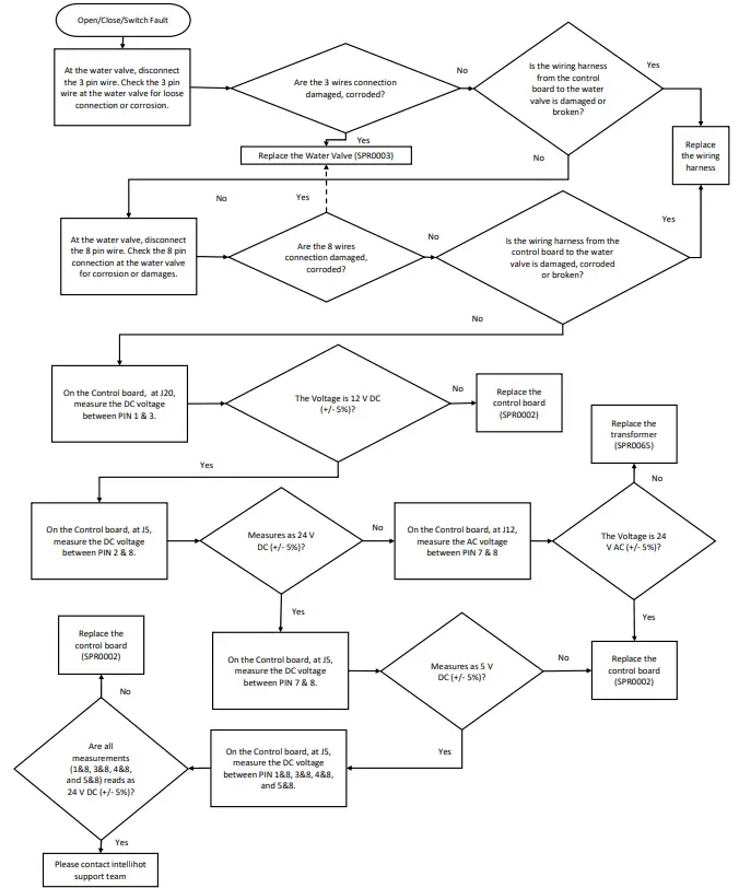
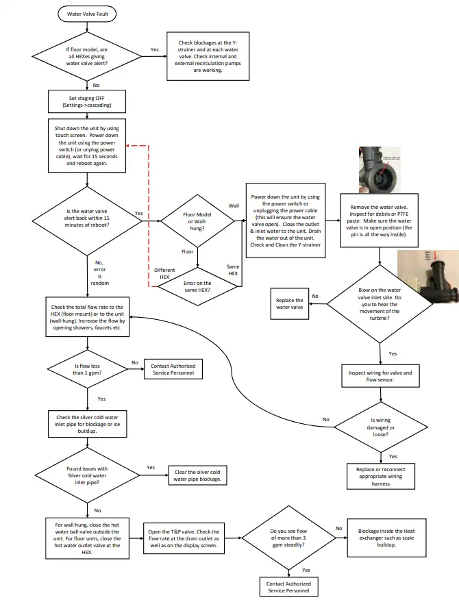
Water Valve Fault
Appendix
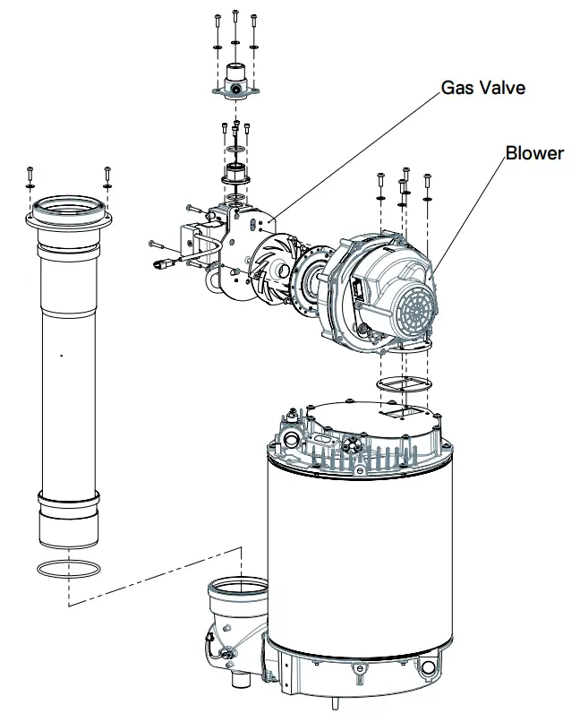
BLOWER REPLACEMENT
The blower is located on the top of the heat exchanger
− Shut off the gas to the heater
− Shut off power to the heater by unplugging the unit from the 120 VAC outlet
− remove the front panel (three screws at top and three at bottom)
− Unplug the display cable from the pcb (press plastic tab and pull)
− lift up and remove the front display bracket
− Unplug all the wiring connections from the blower (press the tabs and pull)
− remove the gas valve wiring located behind the blower
− Unplug the HV cable from the DSI
− Remove the gas connection at the top isolating the unit’s gas supply from the building
− remove phillips screws to remove the aluminum gas fitting at the top the unit
− remove 4 allen screws to remove the aluminum gas adapter fitting
− remove two plastic taps on top of the cabinet to access the screws securing the blower
− remove 4 screws securing the blower from the top using a long screwdriver
− remove the entire blower gas valve assembly from the unit
− remove the gas valve 3 torx screws
− install the gas valve on the new blower
− reverse process to assemble the blower back to the heater
− ensure the gasket is installed between the blower and the top housing
− Install the blower gas valve using 4 screws and a long screw driver
− Install the aluminum gas adapter on top of the gas valve
− Install the gas fitting and secure it using 4 screws to the cabinet
− Install the building gas supply
− Install the blower wiring, HV cable and gas valve wiring
− turn gas supply back on and check for any gas leaks
− turn water on and plug the heater to the outlet
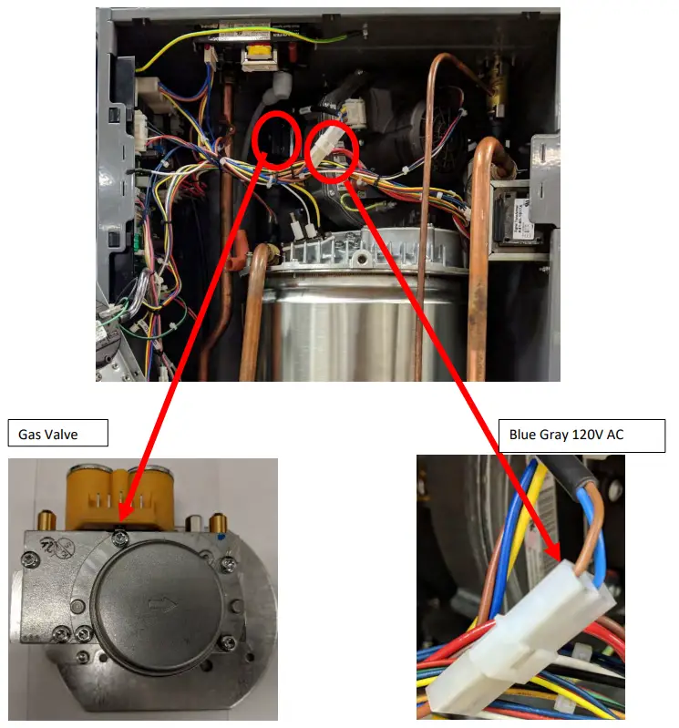
GAS VALVE REPLACEMENT
The blower gas valve assembly is located on the top of the heat exchanger
− Shut off the gas to the heater
− Shut off power to the heater by unplugging the unit from the 120 VAC outlet
− remove the front panel (three screws at top and three at bottom)
− Unplug the display cable from the pcb (press plastic tab and pull)
− lift up and remove the front display bracket
− Unplug all the wiring connections from the blower (press the tabs and pull)
− remove the gas valve wiring located behind the blower
− Unplug the HV cable from the DSI
− Remove the gas connection at the top isolating the unit’s gas supply from the building
− remove phillips screws to remove the aluminum gas fitting at the top the unit
− remove 4 allen screws to remove the aluminum gas adapter fitting
− remove two plastic taps on top of the cabinet to access the screws securing the blower
− remove 4 screws securing the blower from the top using a long screwdriver
− remove the entire blower gas valve assembly from the unit
− remove the gas valve 3 torx screws
− install the new gas valve on the blower 3 torx screws
− reverse process to assemble the blower back to the heater
− ensure the gasket is installed between the blower and the top housing
− Install the blower gas valve using 4 screws and a long screw driver
− Install the aluminum gas adapter on top of the gas valve (ensure the o-ring is in place)
− Install the gas fitting and secure it using 4 screws to the cabinet
− Install the building gas supply
− Install the blower wiring, HV cable and gas valve wiring
− turn gas supply back on and check for any gas leaks
− turn water on and plug the heater to the outlet
Blower/Gas Valve Exploded View
ELECTRODE REPLACEMENT
The electrode is located on the top of the heat exchanger
− Shut off the gas to the heater
− Shut off power to the heater by unplugging the unit from the 120 VAC outlet
− remove the front panel (three screws at top and three at bottom)
− Unplug the display cable from the pcb (press plastic tab and pull)
− lift up and remove the front display bracket
− Unplug the HV cable from the electrode
− Unplug the electrode connection from the controller at connection E12
− Remove the 2 screws & washers securing the electrode
− Remove electrode from HEX assembly.
− Insert new electrode into the HEX assembly, careful to use new probe hole seal
− Fasten the electrode with the 2 screws with washers. Verify that the yellow/green wire is attached beneath the right hand screw.
− Connect the electrode to the controller at connection E12
− Connect the HV cable to the electrode
− turn gas supply back on
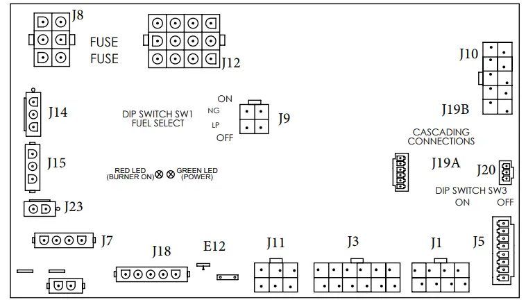
− turn water on and plug the heater to the outlet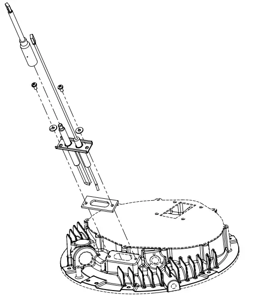 Controller Pin Layout
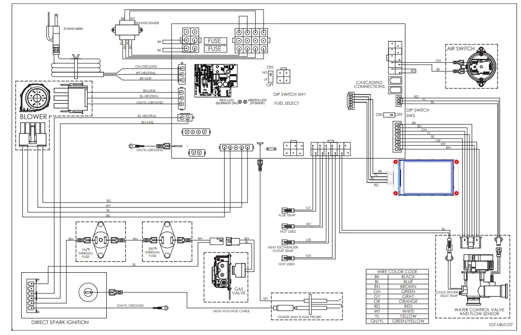
Wiring Diagram (all wall-hung units)
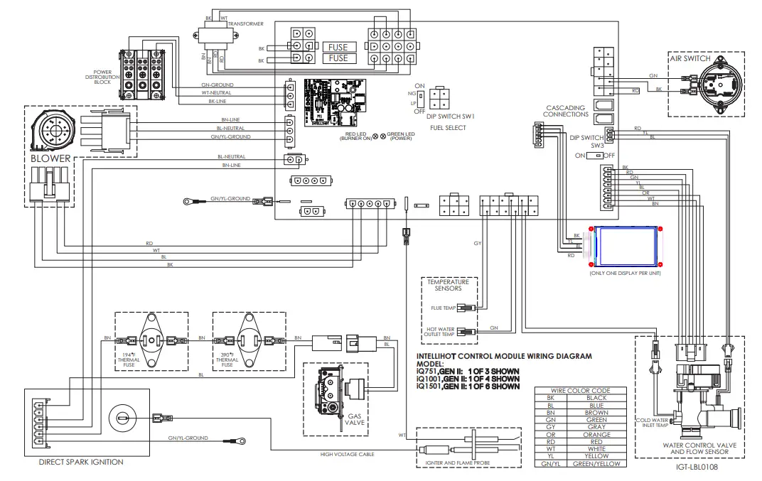
Wiring Diagram (all floor-standing units)
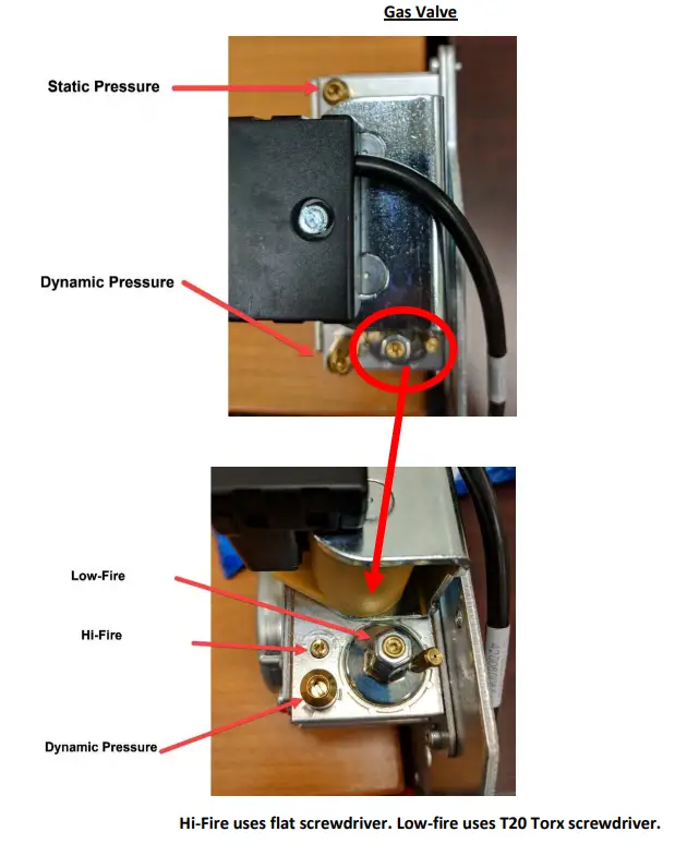
Gas Valve
Resettable overheat switch
![]() www.intellihot.com
www.intellihot.com
2900 W. Main Street, Galesburg IL 61401 |
309.473.8040 main
309.296.8984 fa


