![]() USER’S / INSTALLER’S MANUAL
USER’S / INSTALLER’S MANUAL
![]() Correct disposal of this product (electrical and electronic equipment waste).
Correct disposal of this product (electrical and electronic equipment waste).
THE PRODUCT
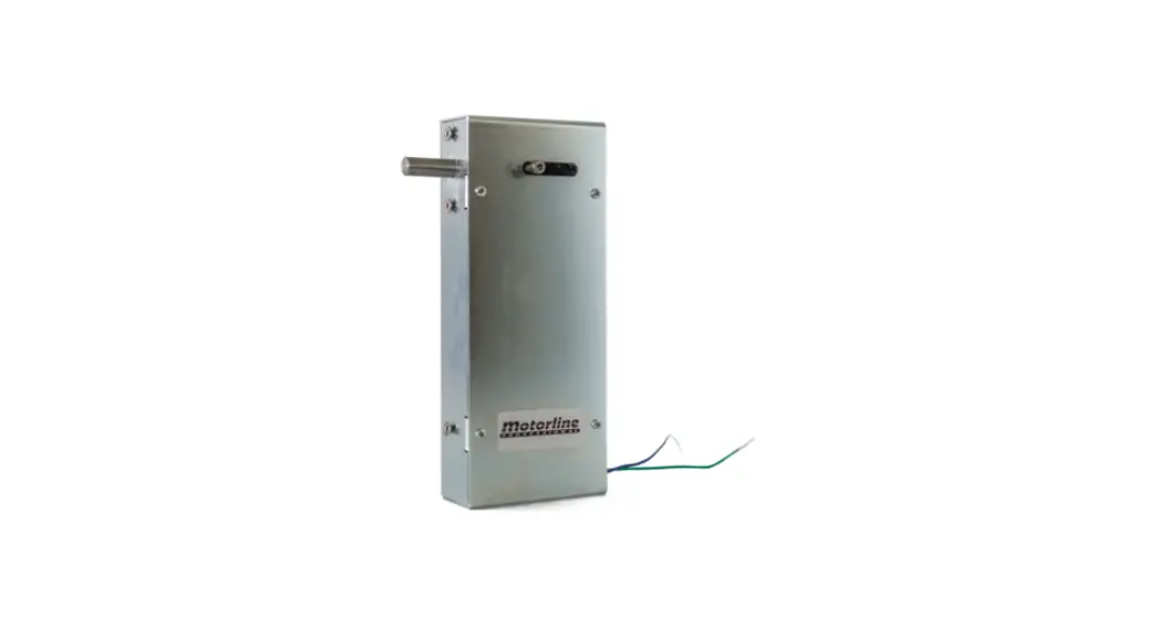
The EF25 lock has been developed for application on sectional doors controled by the MC60 control board.
SAFETY INSTRUCTIONS
- The ELECTROCELOS S.A. is not responsible for the improper use of the product, or other use than that for which it was designed.
- The ELECTROCELOS S.A. is not responsible if safety standards were not taken into account when installing the equipment, or for any deformation that may occur.
- The ELECTROCELOS S.A. is not responsible for insecurity and malfunction of the product when used with components that were not sold by the them.
TECHNICAL CHARACTERISTICS
| • Power Supply | 12V DC |
| • Maximum current | 1.3A |
| • Maximum impulse time | 100ms |
| • Weight | 1.4kg |
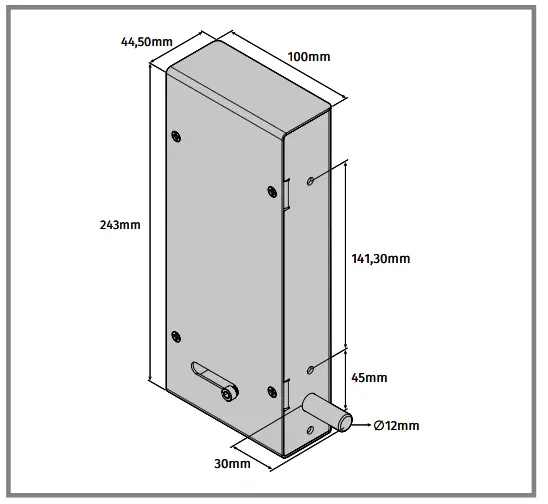
| • Packaging dimensions | 262mm x 116mm x 68mm |
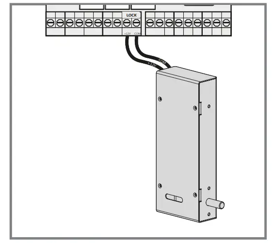
CONNECTION SCHEME TO MC61 C. BOARD
INSTALLATION
The EF25 lock must be installed with a minimum margin of 5 mm from above one of the wheels on the floor guide. When the control board receives a opening order, it must
firstly retract the lock and then iniciate the opening maneuver to ensure that the lock never gets stuck by the gate.
![]() The EF25 lock is designed to work along with the MC60 control board. Only with this control board the correct operation of the components is guaranteed!
The EF25 lock is designed to work along with the MC60 control board. Only with this control board the correct operation of the components is guaranteed!
The EF25 is a lock of double direction, one impulse will be to open and the other, to close.
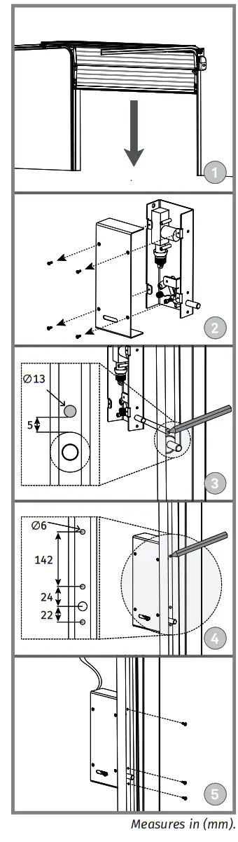
- Close the gate to determine the installationlocation (img.1).
- Remove the cover of the lock unscrewing the 4 bolts (img. 2).
- Make a mark for a ∅13mm hole, 5mm above a wheel of the gate to pass the lock’s latch.
 It is necessary that the lock’s latch is positioned 5 mm above the wheels as shown in the image.
- Reopen the gate.
- Drill the hole using a ∅13mm borer.
- Aim switching latch in the hole and make the remaining markings.
- Drill the holes with ∅6mm drill, apply the lock in the guide and tighten with 3 screws and nuts (img. 4).
- Refit the cover into the lock and close it with the 4 bolts
- Make the electrical connections as shown in the diagram on the left.
 EF25
EF25
V1.2
REV. 11/2021


