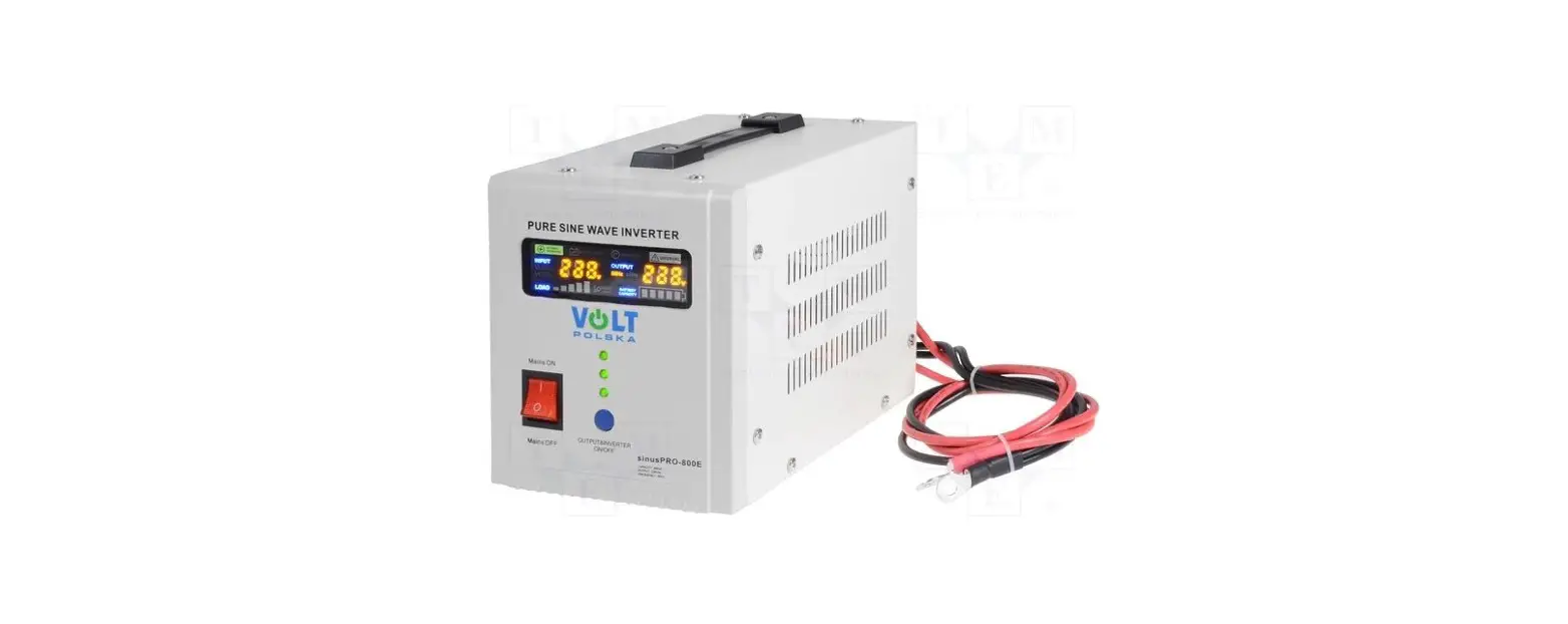
VOLT POLSKA sinusPRO E Pure Sine Wave Electronic Inverters with UPS User Manual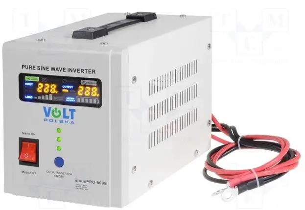
INTRODUCTION
Thank you for purchasing UPS from sinusPRO E series. Please read this user
manual before starting the device.
- One device with built-in DC / AC converter, an uninterruptible power supply unit and an automatic battery charger.
- Toroidal transformer used in the converter ensures high efficiency and low idling current. The device is much more energy-efficient than older constructions that used E-type transformers.
- Fast 32-bit microprocessor ensures accurate and trouble-free operation.
- Intuitive and simple operation thanks to the color LED display, which informs about the current operating status of the device (input and output voltage, battery capacity, charging, etc.).
- Converter generates a pure sinusoidal voltage at the output, which makes it possible to work with practically any type of load.
- High battery charging current (exact values in the table with technical specifications).
- Fast switching from mains supply to operating mode as a UPS enables uninterrupted operation of connected devices.
- Intelligent control of the cooling fan, depending on the actual temperature of the device and the operating status of the inverter.
- Built-in AVR ( Automatic Voltage Regulation).
- Adapted to work with AGM or GELbatteries
STARTING-UPINVERTER
- Open the carton and check, if the the device is not undamaged. Disconnect mains cable from the device.
- Connect battery properly to the device according to the correct polarity (red wire + / black wire -).
- Connect the plug to the mains socket.
- Start the device with the ON / OFF button (hold down 3s until you hear a beep).
- Change the mains charger switch to the „I” or „ON”position to start charging the battery ( AC/ battery charging).
- Connect all devices that you want to use and turn them on one by one after connecting.
SWITCHING-OFF THE INVERTER
- Turn off one by one, all the devices connected to the inverter.
- Change the charger switch to the “0” position to stop the battery charging process.
- Hold down the ON / OFF button for 3 seconds to disconnect the inverter output.
- Disconnect mains plug from the network.
- Disconnect battery from the inverter
Information how to connect CO gas stoves to the power supply!\
When connecting the power plug to the stove, first connect it to a socket with a grounding pin. If the magneto in the furnace does not work (ionization current error), switch the plug to the socket without the grounding pin (turning it 180 degrees from the previous connection).
ATTENTION
- Be careful when connecting the battery, the voltage generated when reverse polarity happen can damage the inverter.
- Do not overload the device above its nominal power. When connecting refrigerators, freezers and other induction appliances / consuming more power on start-up, remember not to exceed 30% of the total power rating of the UPS.
- Do not connect the device on the outdoors, avoid contact with water.
- Remember to install the power supply in the right place, with access to fresh air and a minimum distance of 30 cm from each side of the housing.
- If you notice an incorrect operation / damage to the inverter, contact the manufacturer’s service department.
- If you want to test the device please do not unplug inverter from the mains. Instead turn off mains RCD switch in building to observe proper work of the device. By unpluggin inverter from the mains, neutral – “zero” is cut off from the inverter, which can cause incorrect work of the inverter
OPERATION OF THE DEVICE
| NAME | PICTURE | DESCRIPTION |
| Output switch |  | Pressing and holding the switch for more than 3 seconds will change the state of the inverter to ON or OFF. |
| AC input cord orterminal | 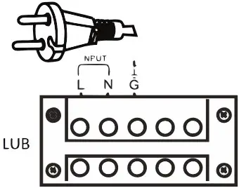 | Connecting the plug to an electrical outlet allows the battery to be charged and to power the output devices through the built-in voltage regulator. |
| Mains switch | 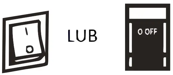 | If the device is connected to the mains supply and the switch is in the “I” position, the battery will be charged and the output devices will be supplied from the mains.Switching to the “0” position will start the inverter and supply the output devices from the battery. |
| Output socket orterminal | 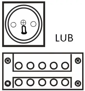 | Connect output devices to the terminal or terminal strip.The maximum power of a single socket is 2000 W. If the power of the output devices is higher, please connect them to the terminal block. |
| Ventilation fan | 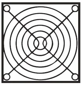 | The cooling fan starts when the UPS inverter is running or when the battery is being charged – when the temperature of the transistors exceeds 45 C |
| Battery input |  | The red terminal should be connected to the positive pole of the battery (+), and black to negative (-). Changing the cables will prevent proper operation of the device. |
LCD DISPLAY ELEMENTS
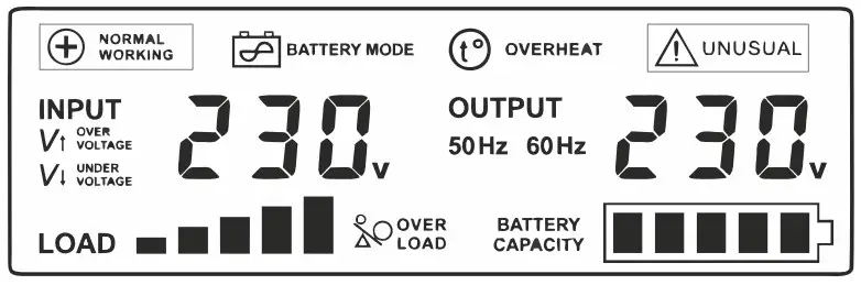
 Normal operation mode, devices powered directly from the 230 V BYPASS network
 No mains voltage, output devices powered from a connected batter
 Overheating of the inverter, emergency output devices are disconnected
 Incorrect battery voltage, short-circuit or overheating of MOSFETtransformers
 Mains voltage is too high
 Mains voltage is too low
 Inverter overload, too high power output devices
 Inverter load level
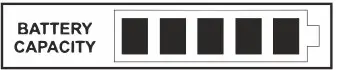 battery charge level, this indicator will flash during charging
 Input voltage value
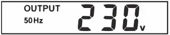 Output voltage value and frequency
TECHNICAL PARAMETERS
| MODEL | 500 E | 800 E | 1000 E | 1500 E | 2000 E | 2200 E | 3000 E | |
| Max power | 500VA | 800VA | 1000VA | 1500VA | 2000VA | 2200VA | 3000VA | |
| Max constant power | 300W | 500W | 700W | 1050W | 1250W | 1600W | 2100W | |
| Idle current (battery mode) | < 1 A | |||||||
|
Input | Voltage | 170~270VAC | ||||||
| Frequency | 45~65Hz | |||||||
| AVR stabiliaztor | In the AC mode, if the voltage supplied from the 230VAC AC mode to the power supply is in the range of 245- 270VAC or 170-216VAC, the power supply will activate the built-in AVR mains voltage stabilizer. | |||||||
| Output | Voltage | 230VAC ± 1% in battery mode: 216-245VAC in AC mode with AVR | ||||||
| Frequency | 50 Hz ± 0.5 Hz | |||||||
| Voltage type | PURE SINE WAVE | |||||||
| Distorions | < 3% THD | |||||||
| Priority selection button (AC / battery) | NO (YES in E PLUS version) | NO | NO | NO | NO | NO | NO | |
| Charge current selection (5/10A) | YES (E PLUS: 2/5/10A) | YES | YES | NO | NO | NO | NO | |
| Securities | overload, temperature, over and undervoltage, before the battery is discharged, short-circuiting, before overcharging | |||||||
| Switching time AC / BATTERY | ≤ 4ms | |||||||
| Battery voltage | 12VDC | 48VDC | ||||||
| Max charge current | 10A | 20A | 10A | |||||
| Dimensions | 146x237x170mm | 146x338x170mm | 220x335x230mm | 220x425x230mm | 220x335x230mm | |||
| Weight | 3,9kg | 4,6kg | 6,4kg | 11,2kg | 12,5kg | 14,5kg | 15,7kg | |
WARRANTY SERVICE COMMENTS
DATE OF PURCHASE
SHIPPING ADDRESS
SIGNATURE / STAMP
DAMAGE DESCRIPTION
SERVICE COMMENTS
FILL IN IF NEEDEED
(*) Cross incorrect
I agree to pay the cost of inverter repair due to:
* expiration of the warranty period / * warranty void
Before proceeding with the repair, service will inform by phone about the exact costs of the repair.
Please attach a copy of the purchase document (receipt or invoice) to the complaint.
The full regulations of service repairs can be found on our website www.voltpolska.pl


