![]()
Pure Sine Wave Inverter
User Manual
Models:
TP10K/TP10KB
TP20K/TP20KB
TP30K/TP30KB
TP40K/TP40KB
Important Safety Instructions
Please reserve this manual for future review. This manual contains all the safety, installation, and operation instructions for the TPower series pure sine wave inverter (“inverter” referred to in this manual).
- Explanation of symbols
Please read related literature accompanying the following symbols to efficiently use the product and ensure personal and property safety.
Please read the related words carefully when you encounter the following symbols in the manual.Symbol Definition TIP Indicate any practical advice for reference. 
IMPORTANT: Indicates a critical tip during the operation, if ignored, may cause the device to run in error. 
CAUTION: Indicates potential hazards, if not avoided, may cause the device damaged. 
WARNING: Indicates the danger of electric shock, if not avoided, would cause casualties. 
WARNING HOT SURFACE: Indicates the risk of high temperature, if not avoided, would cause scalds. 
Read the user manual carefully before any operation. Symbols of inverter

This symbol indicates that after disconnecting the inverter from the grid and battery bank, you should wait for five minutes before touching the internal conductive devices. 
Read the instructions before performing any operation on the inverter. 
Danger! Electric Shock Risk! There are live devices here, only professional and qualified personnel can install and operate it. WARNINGThe entire system should be installed by professional and technical personnel. - Requirements for professional and technical personnel
• Professionally trained.
• Familiar with related safety specifications for the electrical system.
• Read this manual carefully and master related safety cautions. - Professional and technical personnel is allowed to do
• Install the inverter to the specified location.
• Conduct trial operations for the inverter.
• Operate and maintain the inverter. - Safety cautions before installationIMPORTANT
When receiving the inverter, please first check if there is any damage that occurred in transportation. If you find any problem, please contact the transportation company or our company in time. CAUTION• When place or move the inverter, must follow the instructions in the manual.
• When installing the inverter, must evaluate whether the operation area exists any arc danger.WARNING• Do not place the inverter in places where children can touch it.
• The inverter is off-grid type, and it is strictly prohibited to be connected to the grid; otherwise, the inverter would be damaged.
• The inverter is only allowed for stand-alone operation. It is prohibited to connect multiple units’ output in parallel or series; otherwise, the inverter would be damaged. - Safety cautions for mechanical installationWARNING
• Before installation, must make sure the inverter has no electrical connection.
• Ensure the heat dissipation space for the inverter installation. Do not install the inverter in humid, greasy, flammable, explosive, dust accumulative, or other severe environments. - Safety cautions for electrical connectionCAUTION
Check if all the wiring connections are tight to avoid the danger of heat accumulation CAUTION due to a loose connection. WARNINGBoth utility input and AC output are of high voltage, do not touch the wiring WARNING connection to avoid electric shock. - Safety cautions for inverter operationWARNING HOT
SURFACEWhen the inverter is working, its heat sink and casing will generate a lot of heat; the temperature would be very high. Please do not touch it. CAUTIONWhen the inverter is working, please do not open the inverter cabinet to operate. - The dangerous operations which would cause electric arc, fire or explosion
• Hot-plug the high voltage fuse on the inverter DC side.
• Touch the wire end, which hasn’t been insulation treated and maybe electriferous.
• Touch the wiring copper row, terminals, or internal devices which may be electriferous.
• The power cable connection is loose. Screw or other spare parts inadvertently falls into the inverter.
• Improper operations by untrained non-professional or technical personnel.WARNINGOnce an accident occurs, it must be handled by professional and technical personnel. Any incorrect operation would cause a more severe accident. - Safety cautions for stopping the inverter
• Firstly turn off the breakers on the utility input side and AC output side, then turn off the DC switch;
• After the inverter stop working for five minutes, the internal conductive devices could be touched;
• The inverter can be restarted after removing the faults which may affect its safety performance;
• There are no maintenance parts in the inverter; please contact our after-sales service personnel if any maintenance service is required. - Safety cautions for inverter maintenance
• Testing equipment is recommended to check the inverter to make sure there is no voltage or current;
• When conducting electrical connection and maintenance work, must post temporary warning signs or put up barriers to prevent unrelated personnel from entering the electrical connection or maintenance area;
• Improper maintenance operation to the inverter may cause personal injury or equipment damage;
• Please wear an anti-static wrist strap to prevent static damage or avoid unnecessary contact with the circuit board.CAUTIONThe inverter’s safety mark, warning label, and nameplate should be visible, not CAUTION removed or covered.
Product Overview
Information & Features
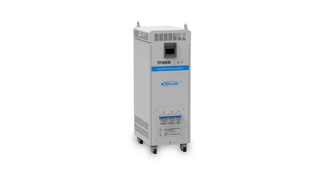
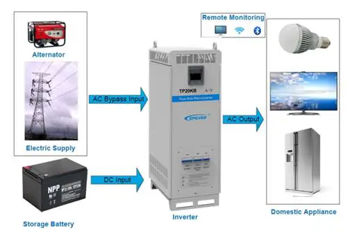
TPower series is designed as a pure sine wave inverter, which converts 110/220VDC to220/230VAC. This device consists of a DC-AC inverting module and an AC-AC bypass module in parallel. It also features high reliability, high efficiency, concise appearance, full protection, easy installation, and operation functions.
DC-AC inverting module is an intelligent and fully digitally designed component with advanced SPWM technology. The module is designed with the pure sine wave output to convert 110/220VDC to220/230VAC for multiple types of AC loads, such as home appliances, electric tools, industrial devices, audio equipment, and solar photovoltaic system.
AC-AC bypass module used an advanced control algorithm to ensure output voltage stability and achieve the fast switching feature. Also, the high reliability and high-performance semiconductor inside the module reduces the size and prolongs service life.
The 4.2 inches segment type of LCDs the system operation data and states in real-time. The case in sheet-metal design is featured with high intensity and shielding electromagnetic interference. Also, the universal rotary caster is optional for the system, which contains lifting support feet to fix or move the inverter at any time and improve product mobility and flexibility.
Features
- Advanced SPWM technology and pure sine wave output
- Fully digitalized voltage and current double closed-loop control
- Low output harmonic distortion(THD3%)
- Mode selection of bypass priority and inverter priority
- Output voltage 220/230VAC and frequency 50/60Hz selectable
- Real-time power query and output power statistics function
- Automatic protection features of the short circuit, overheating, and overload.
- 4.2 inches LCD the system operation data and state dynamically with a friendly AI interface
- Multiple LED indicators show the operating status of the system in real-time
- Designed with soft boot control to avoid the battery be damaged by high current impact when turning on the system
- AC OUT button controls the AC output individually
- Smart fan control reduces energy consumption and noise
- Use popular semiconductor modules with high reliability and low power consumption
- Designed with remote switch & RS485 communication interface to achieve the features of remote monitoring and hardware Stop & Start, also the Wi-Fi and Bluetooth communication modules are selectable
- Universal rotary caster is optional for free movement and fixation. Modular design, easy maintenance, and repair
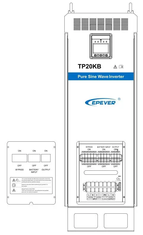
Structure
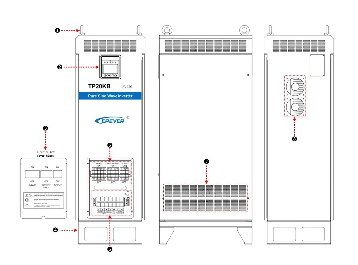
| ❶ | Ring 2 pieces | Carry the inverter. |
| ❷ | Display unit | Include LED indicators, LCD, and buttons to indicate and display system operation state and parameters. See Chapter 3. |
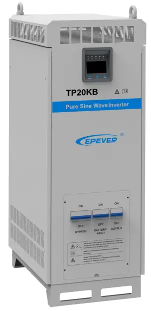
| ❸ | Junction box cover plate | To cover the terminals and circuit breakers. |
| ❹ | Pedestal⑴ | To fixed the inverter |
| ❺ | Input/output circuit breaker group ⑵ | Protective devices to safely cut off the current. |
| ❻ | Input /Output terminal ⑵ | Wire connection with utility, battery, load, and grounding. |
| ❼ | Heat dissipating hole | Dissipate the heat inside the inverter. |
| ❽ | Fan ⑶ | Forced cooling for the inverter. |
(1) FOOT MASTER caster(Optional accessory)
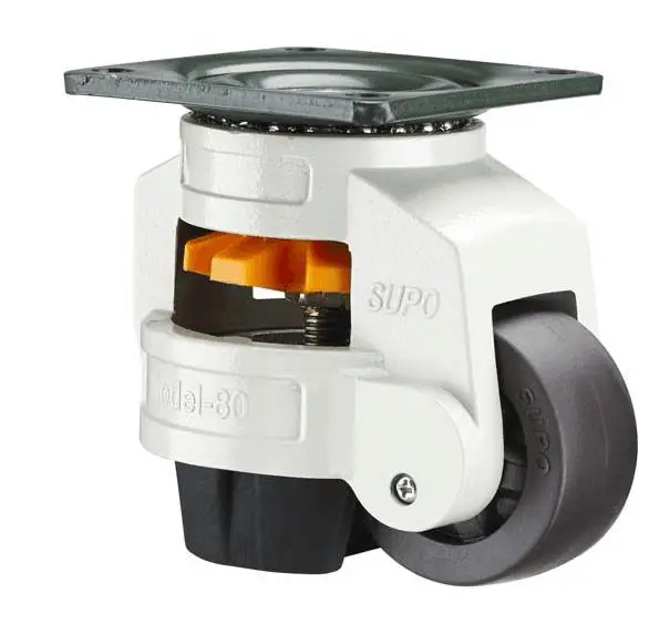 Rotate clockwise to raise the supporting feet, then to move the inverter.
Rotate counterclockwise to lower the supporting feet, then to fix the inverter.
(2) Terminals and breakers
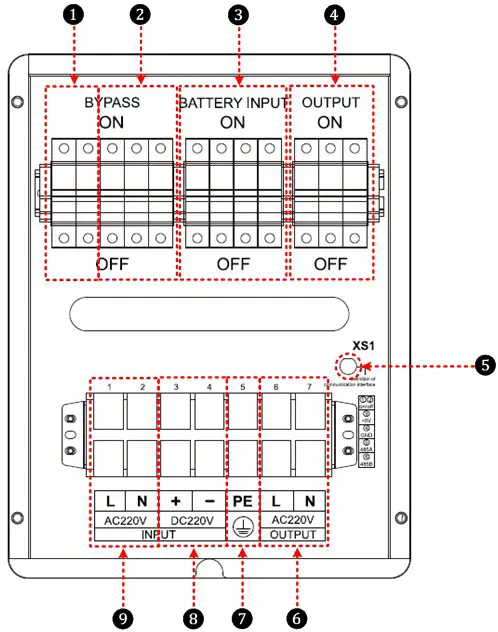
| ❶ | Bypass input arrester | ❻ | AC output terminals |
| ❷ | Bypass input breaker | ❼ | Grounding terminal |
| ❸ | Battery input breaker | ❽ | Battery input terminals |
| ❹ | AC output breaker | ❾ | Bypass input terminals |
| ❺ | Remote switch & RS485 communication port ★ | ||
★ Remote switch & RS485 communication port pin definitions:
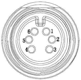
| 1-Red 2-White | ON/OFF |
| 3-Yellow | +5Vdc |
| 4-Black | GND |
| 5-Blue | 485A |
| 6-Green | 485B |
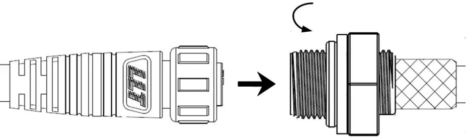
★ Interface connection method :
 (3) DC fan and AC fan DC fan (2 pieces):
When the radiator temperature rises to 45 above, the DC fans will start; the DC fans will stop when the radiator temperature declines to 35 below.
| DC fans have the self-checking function when the inverter is powered on. The DC IMPORTANT fans would automatically run for three seconds. |
AC fan (3 pieces):
Inverter priority:
When the internal temperature rises to 35 above, and with inverter output, the AC fans will start. The AC fans will stop when internal temperature declines to 30 below or with no inverter output.
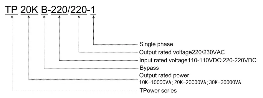
Name definition
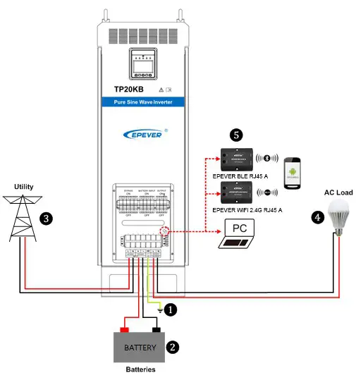
Connection schematic diagram
| The AC equipment must be determined according to the output power of the inverter. Do not connect the load exceeding the inverter’s maximum input power. Otherwise, the WARNING inverter may be damaged. |
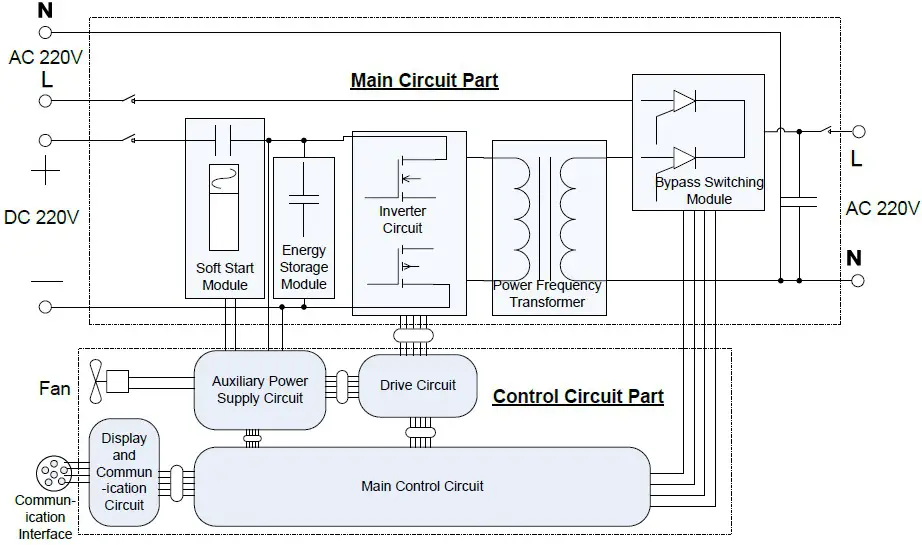
Electrical schematic diagram
Installation
Warning
- Please read the manual carefully to get familiar with the installation steps before installation.
- Be very careful when installing the batteries, especially flooded lead-acid batteries. Please wear eye protection, and have fresh water available to rinse if any contact with battery acid.
- Keep the battery away from any metal objects, which may cause a short circuit of the battery.
- Loose connections and corroded wires may result in high heat that can melt wire insulation, burn surrounding materials, or even cause a fire. Ensure tight connections and use cable clamps to secure cables and prevent them from swaying in motion.
- Select the system connection cables according to the current density no higher than 5A/mm2. (Following the National Electrical Code Article 690, NFPA70).
- For outdoor installation, keep out of the direct sunshine and rain infiltration.
- High voltage exists inside the inverter after turning off the switch. Do not open or touch the internal devices and wait five minutes before conducting related operations.
- Please do not install the inverter in humid, greasy, flammable, explosive, dust accumulative, or other severe environments.
- Prohibit reverse connection at the battery input end; otherwise, it will easily damage the equipment or cause unpredictable danger.
- Both utility input and AC output are of high voltage; please do not touch the wiring connection.
- When the fan is working, please do not touch it to avoid injury.
Wire& breaker selection
Wiring and installation mode should comply with national and local electrical code requirements.
- Wire and circuit breaker selection for utility input
Model Utility wire size Breaker TP10KB 25mm2/3AWG AC/2P—63A TP20KB 35mm2/1AWG AC/2P—100A TP30KB 42mm2/1AWG AC/2P—150A TP40KB 50mm2/1/0AWG AC/2P—200A - Wire and circuit breaker selection for battery
Model Battery wire size Breaker TP1OK
TP10KB35mm2/1AWG(110VDC) DC/2P 125A 25mm2/3AWG(220VDC) DC/2P-63A TP2OK
TP2OKB35mm2/1AWG DC/2P 125A TP30K
TP30KB42mm2/1AWG DC/2P—200A TP40K
TP40KB50mm2/1/0AWG DC/2P—250A - Wire and circuit breaker selection for AC output
Model AC wire size Breaker TP1OK
TP1OKB25mm2/3AWG AC/2P-63A TP2OK
TP2OKB35mm2/1 AWG AC/2P 100A TP3OK
TP3OKB42mm2/1 AWG AC/2P 150A TP4OK
TP4OKB50mm2/1/0AWG DC/2P 200A
| • The wire size is for reference only. Use thicker wires to lower the voltage drop and improve the system performance when the distance between utility and inverter or between inverter and batter is far. • The above wire size and circuit breaker size are for recommendation only. Please choose a suitable wire and circuit breaker according to the practical situation. |
Instructions
Installation steps:
Step1: Professional personnel read this manual carefully.
Step2: Determine the installation location and heat dissipation space.
Move the equipment: as the equipment is relatively large, it is recommended to use a forklift or crane; if the ground is flat, it can be moved by wheels.
Place the equipment: As the equipment is heavy, it is recommended to be placed on flat ground, with 300mm space reserved all around, to ensure heat dissipation.
Fix the equipment: If the optional caster is chosen, rotate counterclockwise to fix and rotate clockwise to move.
| Risk of explosion! Never install the inverter with flooded batteries in a sealed enclosure! Do not install the WARNING device in a confined area where battery gas can accumulate. |
Step3: Takedown the junction box cover plate with special tools.
Step4: Wiring
 Wiring order: Ground—-Battery—-Utility—-AC loads
| Never connect the utility to the inverter output; otherwise, the inverter may be damaged. |
Grounding
The voltage of the whole system exceeds the safety voltage level. Thus reliable grounding is needed. The grounding wire shall be the thicker wire no less than 35mm2) and shall be as short as possible. The grounding point shall be as close as possible to the inverter.
| When wiring, follow the order | |
| • Make sure all the wiring connections are reliable; otherwise, massive heat would accumulate at the connection points to damage the terminals or even cause a fire. • Danger, high voltage! Terminals of the Utility input, AC output, and DC input produce high voltage, do not close the breakers during wiring, and ensure each component’s correct polarity. |
Step5: Connect accessories
- Mobile APP For Android only)
Download software: www.epever.com–EPEVER (TP)
Communication cable: M12-6-male pin + crystal head-1000mm-v1.0
Modules: EPEVER WiFi 2.4G RJ45 A and EPEVER BLE RJ45 A - PC Software
Download software: www.epever.com–Inverter Monitor (TP)
Communication cable:
- M12-6-male pin + crystal head-1000mm-v1.0
- RJ45 Coupler
- CC-USB-RS485-0.3mm2-3m-V1.1
Step6: Double-check the reliability of wiring connections.
Step7: Put on the cover plate. Indicator: Inverter indicator on solid
LCD:
Step8: Close the bypass circuit breaker 13
The indicator: Utility indicator on solid
LCD:
Step9: Close the load circuit breaker
LCD:
 Step10: Inverter output
Method 1: Press the “AC output” button for 3 seconds, the inverter would start the output.
Method 2: Connect the remote switch, short-circuit cable 1(red), cable 2(white) of the remote switch, and RS485 communication interface; the inverter would start the output. Indicator: Inverter indicator slowly flashing and load indicator on solid.
LCD:
Step11: Turn on the load
LED indicators: Inverter and load indicators are slowly flashing.
| • If the power is supplied to the different AC loads, it is suggested to turn on the loads with a larger surge current till the load works well, then turn on the loads with a smaller surge current. Especially for inductive loads, they should be turned on one by one. Do not turn on the loads simultaneously to not cause excessive impact to the inverter, to shorten its life span. • If the inverter is not in regular operation, or LCD or indicator displays abnormal, refer to Section 5 to clear the fault or contact the after-sale service personnel of our company. |
Step12: Power off the equipment
- Disconnect the AC load circuit breaker.
- Long press the “AC output” button to turn off the inverter output.
- Disconnect the bypass circuit breaker.
- Disconnect the battery circuit breaker.WARNING
• As electricity exists in the capacitance, the LCD screen would be off after 30 seconds; wait 5 minutes before opening the equipment to repair.
• The inverter has a soft stat design and only takes effect when it starts. Do not frequently switch the input circuit breaker when the inverter is incompletely powered off. Otherwise, the input battery would undergo a high current impact. That is, the input circuit breaker can be closed again after the LCD screen is off.
WARNING | After the inverter is disconnected from the utility and battery bank, you must wait 5 minutes before touching the internal conductive devices. |
Output voltage/frequency grade switch
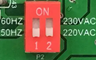
When the dial switch 1 is placed to the ON side, the output frequency is 60Hz, otherwise it is 50Hz, When the dial switch 2 is placed to the ON side, the output voltage is 230VAC, otherwise it is 220VAC.
Operating steps:
Open the cover plate on the inverter right side and find the dial switches on the control board, located on the top left corner; see the picture above. Set the output voltage/frequency according to demand, then restart the inverter to take effect.
| • The factory default output voltage is 220VAC, and the output frequency is 50Hz. • The accessories can refer to the Packing List. |
Interface
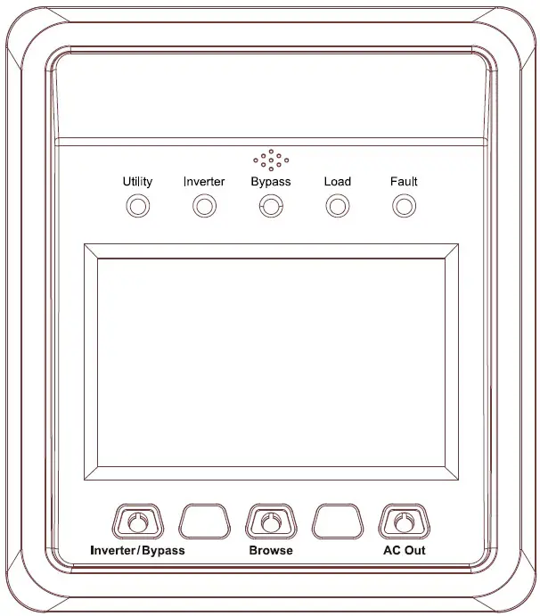
Indicator
| Indicator | Color | Status | Instruction |
| Utility | Green | OFF | No utility input |
| On Solid | Utility input but no load | ||
| Slowly Flashing(0.5Hz) | Utility bypass with load | ||
| Fast Flashing(2.5Hz) | Utility fault | ||
| Inverter | Green | OFF | Inverter OFF |
| On Solid | Inverter Priority | ||
| Slowly Flashing(0.5Hz) | Inverter working | ||
| Fast Flashing(2.5Hz) | Inverter fault | ||
| Bypass | Green | OFF | Bypass OFF |
| On Solid | Bypass Priority | ||
| Slowly Flashing(0.5Hz) | Bypass working | ||
| Fast Flashing(2.5Hz) | Bypass fault | ||
| Load | Green | OFF | Power off the inverter |
| On Solid | AC output but no load | ||
| Slowly Flashing(0.5Hz) | AC output with load | ||
| Fast Flashing(2.5Hz) | Output voltage abnormal | ||
| Fault | Red | OFF | Inverter normal |
| On Solid | Inverter fault |
Buzzer
| Buzzer | Instruction |
| No beep | No operation and fault |
| One beep | Operation succeed |
| Buzzer beep every10s | Fault prompt |
| Buzzer beep every1s | Fault warning |
| Button | Operation | Instruction |
| Inverter/Bypass | Press the button | Return the voltage interface quickly |
| Press the button and hold on 3s | Switch the inverter and bypass mode | |
| Browse | Press the button | Browse the Utility/Battery/Load column parameters |
| Press the button and hold on 3s | Browse the Utility/Battery/Load column parameters quickly | |
| AC output | Press the button and hold on 3s | Switch the inverter output and no output mode |
| Inverter/Bypass + Browse | Press the button and hold on 3s | Clear the generated energy |
| Browse + AC output | Press the button and hold on 3s | Clear the faults |
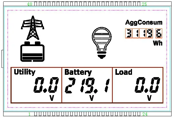
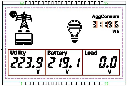
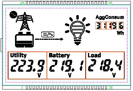
LCD Display
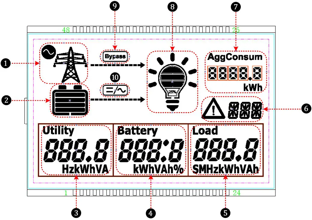
| ❶ | Utility | ❻ | Fault code |
| ❷ | Battery | ❼ | AggConsum |
| ❸ | Utility parameters Voltage/Current/Power/Frequency | ❽ | Load status |
| ❹ | Battery parameters Voltage/Current/Power | ❾ | System running in bypass status |
| ❺ | Battery parameters Voltage/Current/Power | ❿ | System running in inverter status |
Icon
| Icon | Instruction | Icon | Instruction |
| No Utility connecting | Load≤25% | ||
| Utility connecting | Load(25~50%) | ||
| Inverter output ON | Load(50~75%) | ||
| Inverter output OFF | Load(75~100%) |
Operation
- Turn on the load:
Operation:
Press the “AC output” button for 3seconds; the load indicator changes to ON status.
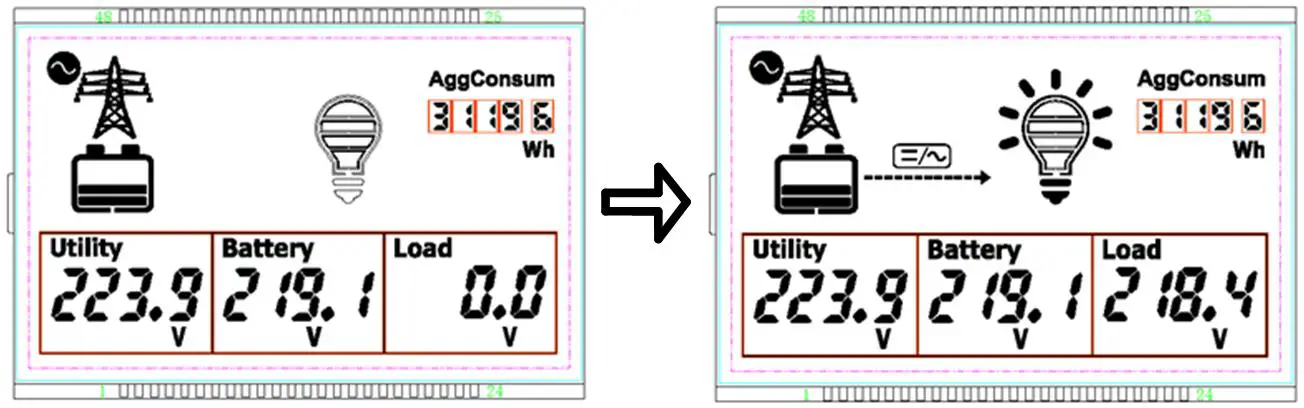
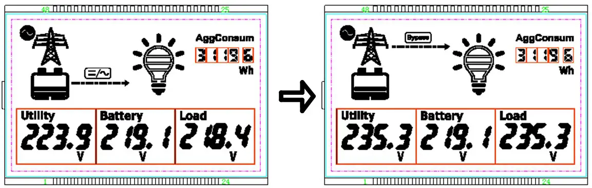
- Switch from inverter mode to bypass mode
Operation:
Press the “inverter/bypass” button for 3seconds; bypass indicator changes from off to solid on, inverter indicator changes to off status.
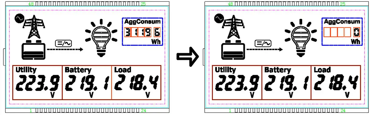
- Clear electricity mode
Operation:
Press the “inverter/bypass” and “browse” buttons for 3seconds together to clear the accumulated consumed electricity.
- Clear fault
Operation:
Under failure state, short press any button, the buzzer would stop sounding, but the failure code would still be displayed.IMPORTANTIn the unrecoverable fault mode, press and hold the “Browse + AC output” buttons to clear the fault, and the inverter will resume output. It is confirmed that the fault has IMPORTANT been eliminated before pressing the buttons.
Protection
| Protection | Phenomenon | Protection | Recovery |
| Input reverse polarity protection | When DC input reverses polarity, the LCD would be off. | The equipment would not be damaged. | Resume work normally after correction. |
| Input over voltage protection | Inverter mode: DC input voltage exceeds the max. input voltage Fault code “10V” Buzzer sounds in short cycle | The Inverter stops working and switches to the bypass mode. AC output continues (If no bypass input is available, or the bypass circuit breaker is open, AC output will stop.) | When the input voltage backs to normal, fault warning stops, auto switch to inverter mode. |
| Bypass mode: DC input voltage exceeds the max. input voltage Fault code “10V” Buzzer sounds in a long cycle | Bypass works normally, AC output continues. | When the input voltage backs to normal, the fault warning stops. | |
| Input low voltage protection | Inverter mode: DC input voltage is lower than the min. input voltage Fault code “ILV” Buzzer sounds in short cycle | The Inverter stops working and switches to the bypass mode. AC output continues (If no bypass input is available, or the bypass circuit breaker is open, AC output will stop.) | When the input voltage backs to normal, fault warning stops, auto switch to inverter mode. |
| Bypass mode: DC input voltage is lower than the min. input voltage Fault code “ILV” Buzzer sounds in a long cycle | Bypass works normally, AC output continues. | When the input voltage backs to normal, the fault warning stops. | |
| Output voltage abnormal | AC output voltage exceeds the range of 220±20Vac Fault code “OVA” Buzzer sounds in short cycle | AC output stops. | AC output voltage recovers to the range of 220±20Vac. |
| Output overload | The output power is 1.1 times greater than the rated power Fault code “OOL” Buzzer sounds in short cycle | AC output stops | Reduce the load power. |
| Output short circuit | Fault code “OSC” Buzzer sounds in short cycle | Shut off the output immediately, auto recover the output three times (The first time delay for 5 seconds, the second time delay for 10 seconds; the third time delay for 15 seconds). | Recover the output after the load short circuit failure is cleared The equipment would auto-recover the output every 24 hours after the fault happened. If the fault is cleared, the load output will recover only after manually restart. |
| IGBT over current | Fault code “ISC” Buzzer sounds in short cycle | Shut off the output immediately, auto recover the output three times (The first time delay for 5 seconds, the second time delay for 10 seconds; the third time delay for 15 seconds). | Suppose the IGBT over current state continues after three times auto-recovery. In that case, the output will recover only when the fault is cleared and manually restart. |
| Radiator over- temperature protection | The radiator temperature exceeds 85°C Fault code “ROT” | AC output stops | When the temperature backs to normal, the fault warning stop, AC output recovers. |
| Internal over temperature protection | Internal temperature exceeds 60°C Fault code “10T” | AC output stops | When the temperature backs to normal, the fault warning stop, AC output recovers. |
| Bypass overvoltage | Inverter mode: Bypass input voltage exceeds 264VAC Fault code “BOV” Buzzer sounds in a long cycle | The inverter works normally, AC output continues. | When the bypass input voltage backs to normal, the fault warning stops. |
| Bypass mode: Bypass input voltage exceeds 264VAC Fault code “BOV” Buzzer sounds in short cycle | Auto switch to inverter mode, AC output continues (if the inverter circuit has fault too, AC output will stop). | When the bypass input voltage backs to normal, fault warning stops, auto switch to bypass mode. | |
| Bypass low voltage | Inverter mode: Bypass input voltage lower than 176VAC Fault code “BLV” Buzzer sounds in long cycle | The inverter works normally, AC output continues. | When the bypass input voltage backs to normal, the fault warning stops. |
| Bypass mode: Bypass input voltage lower than 176VAC. Fault code “BLV” Buzzer sounds in short cycle | Auto switch to inverter mode, AC output continues (if the inverter circuit has fault too, AC output will stop). | When the bypass input voltage backs to normal, fault warning stops, auto switch to bypass mode. | |
| Bypass frequency abnormal | Inverter mode: Bypass input frequency exceeds the 50Hz/60Hz±10% Fault code “BFA” Buzzer sounds in long cycle | The inverter works normally, AC output continues. | When the bypass input frequency backs to normal, the fault warning stops. |
| Bypass mode: Bypass input frequency exceeds the 50Hz/60Hli10% Fault code “BFA” Buzzer sounds in short cycle | Auto switch to inverter mode, AC output continues (if the inverter circuit has fault too, AC output will stop). | When the bypass input frequency backs to normal, fault warning stops, auto switch to bypass mode. | |
| Communication fault | Fault code “CFA” | AC output continues | Turn on/off the inverter through the remote switch at the communication interface. |
Troubleshooting
DC input troubleshooting
| Fault | Fault Code | Working mode | LED indicators | Buzzer | Status | Troubleshooting |
| Input reverse polarity | — | — | — | — | LCD screen off | Correct the wire connection of DC input polarity. |
| Input over voltage | 10V | Inverter mode | Inverter indicator fast flashing Fault indicator on solid | 1S | Recover | Check whether the DC input voltage exceeds the max. input voltage. Recover when voltage declines to the rated input voltage. |
| Bypass mode | 10S | |||||
| Input low voltage | ILV | Inverter mode | Inverter indicator fast flashing Fault indicator on solid | 1S | Check whether the DC input voltage is lower than the min. input voltage. Recover when the voltage rises to the rated input voltage. | |
| Bypass mode | 10S |
Inverter output troubleshooting
| Fault | Fault Code | Working mode | LED indicators | Buzzer | Status | Troubleshooting |
| Output voltage abnormal | OVA | — | Fault indicator on solid | 1S | Recover | Check whether the inverter output voltage exceeds the 220VAC±20. |
| Output overload | OOL | — | Fault indicator on solid | Locked up | Check whether the load power is greater than 1.1 times the rated power | |
| Output short circuit | OSC | — | Fault indicator on solid | Check whether the inverter output line is short. |
Utility input troubleshooting
| Fault | Fault Code | Working mode | LED indicators | Buzzer | Status | Troubleshooting |
| Bypass overvoltage | BOV | Inverter mode | Bypass indicator fast flashing Fault indicator on solid | 10S | Recoverable | Check whether the bypass input voltage exceeds 264VAC. Recover when voltage declines to 220VAC. |
| Bypass mo | 1S | |||||
| Bypass low voltage | BLV | Inverter mode | 10S | Check whether the bypass input voltage is lower than 176VAC. Recover when the voltage rises to 220VAC. | ||
| Bypass mode | 1S | |||||
| Bypass frequency abnormal | BFA | Inverter mode | 10S | Check whether the bypass input frequency is in the range of 50Hz/60Hz±10%. | ||
| Bypass mode | 1S |
Others
| Fault | Fault Code | Working mode | LED indicators | Buzzer | Status | Troubleshooting |
| IGBT over current | ISC | Inverter mode | flashing Fault indicator on solid | 1S | Locked up | (1) After power off, check whether the load is a short circuit. (2) Five minutes after power off, open the left side cover plate, check whether the IGBT screw or wire connection is loose, check whether the IGBT is broken. |
| Radiator over temperature | ROT | — | Fault indicator on solid | Recoverable | Check whether the backside fan usually works. Reduce the load power. | |
| Internal over temperature | 10 T | – | Fault on solid | Check whether the AC fans are working normally. Reduce the load power Check whether the upside fan works normally; check whether the ambient temperature exceeds 50°C. Reduce the load power | ||
| Communication fault alarm | CFA | — | Fault on solid | After power off, open the right side cover plate and check whether the panel’s wiring connections are loose. |
Maintenance
The following inspections and maintenance tasks are recommended at least two times per year for the best performance.
- Make sure no block on airflow around the inverter.
- Clear up any dirt and fragments on the radiator. Check all the naked wires to ensure insulation is not damaged for serious solarization–frictional wear, dryness, insects or rats, etc. Repair or replace some wires if necessary.
- Check and confirm that indicator and display are consistent with required. Pay attention to any troubleshooting or error indication. Take corrective action if necessary.
- Confirm that all the terminals have no corrosion, insulation damaged, high temperature, or burnt/discolored sign, tighten terminal screws to the suggested torque.
- Check for dirt, nesting insects, and corrosion. If so, clear up in time.
- Check and confirm that the lightning arrester is in good condition. Replace a new one in time to avoid damaging the inverter/charger and even other equipment.WARNING
Risk of electric shock!
Ensure that all the power is turned off. All the power in the capacitor has been discharged before performing the above operations.
Specifications
| Item | TP10K-110/220-1 | TP1OKB-110/220-1 | TP10K-220/220-1 | TP1OKB-220/220-1 |
| Technical parameters | ||||
| Rated input voltage | 110VDC | 220 DC | ||
| Battery Input voltage range | 93VDC – 146VDC | 187VDC – 293VDC | ||
| Max. input current | 122A | 60A | ||
| Rated output power | 10000VA | |||
| Output voltage | 2201230VAC±3% (Battery power mode) | |||
| Output frequency | 50F1z/60Hz±3°/0 (Battery power mode) | |||
| Output power factor | 0.2 ~1 | |||
| Output way | Single-phase | |||
| Output wave | Pure Sine Wave | |||
| Output THD | 5 3%(Resistive load) | |||
| Max. inverter efficiency | > 90%(Resistive rated load) | |||
| Bypass Input voltage range | — | 170VAC – 275VAC | — | 170VAC – 275VAC |
| Bypass transfer time | 12mS | |||
| No-load consumption | 52% | |||
| Backlight | 30S (Turn on by pressing the button) | |||
| Mechanical Parameters | ||||
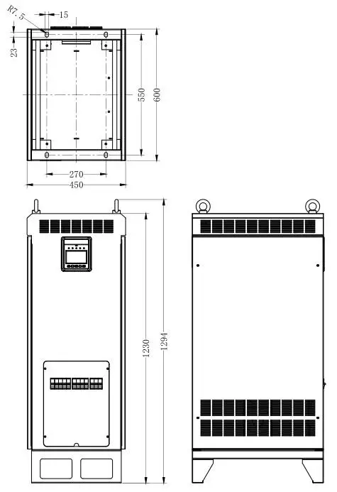
| Dimension(LxWXH) | 600×450 x 1294mm | |||
| Net Weight | 150Kg | 148Kg | ||
| Item | 1 TP20K-2201220-1 | TP2OKB-2201220-1 | TP30K-220/220-1 | TP3OKB-220/220-1 |
| Technical parameters | ||||
| Rated input voltage | 220VDC | |||
| Battery Input voltage range | 185VDC – 295VDC | 185VDC – 295VDC | ||
| Max. input current | 150A | 234A | ||
| Rated output power | 20000VA | 30000VA | ||
| Output voltage | 220/230VAC±3%(Battery power mode) | |||
| Output frequency | 50Hz/60Hz±3%(Battery power mode) | 50Hz/60Hz±3°/0(Battery power mode) | ||
| Output power factor | 0.2 – 1 | |||
| Output way | Single-phase | |||
| Output wave | Pure Sine Wave | |||
| Output THD | 5 3%(Resistive load) | |||
| Max. inverter efficiency | > 90%(Resistive rated load) | >90%(Resistive rated load) | ||
| Bypass Input voltage range | — | 170VAC – 275VAC | — | 170VAC – 275VAC |
| Bypass transfer time | 12mS | |||
| No-load consumption | 52% | 52% | ||
| Backlight | 30S(Turn on by p essing the button) | |||
| Mechanical Parameters | ||||
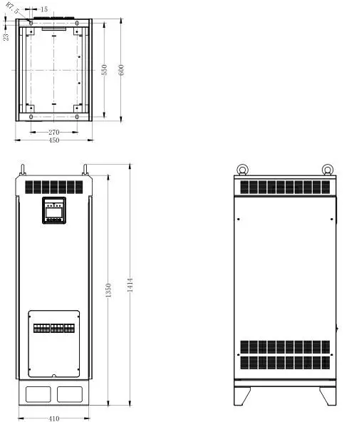
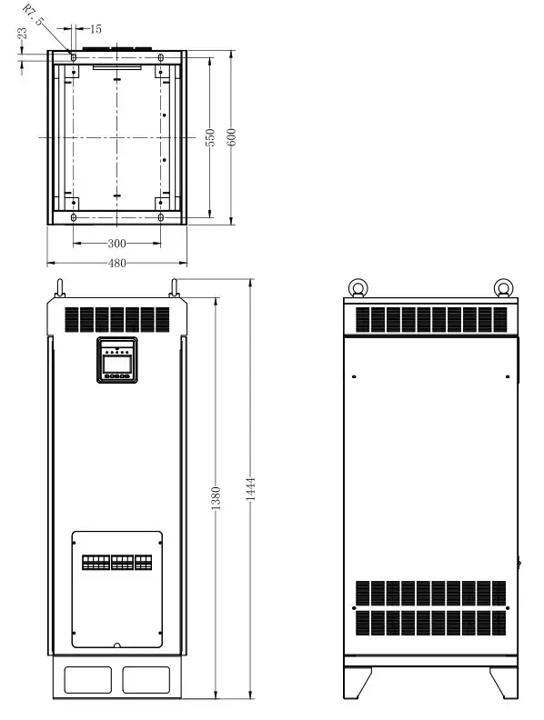
| Dimension(LxWxH) | 600x450x 1414mm | 600x480x 1444mm | ||
| Net Weight | 188Kg | 228Kg | ||
| Item | I TP40K-220/220-1 | I TP4OKB-220/220-1 |
| Technical parameters | ||
| Rated input voltage | 220VDC | |
| Battery Input voltage range | 203VDC – 280VDC | |
| Max. input current | 263A | |
| Rated output power | 40000VA | |
| Output voltage | 220/230VAC±3%(Battery power mode) | |
| Output frequency | 50Hz/60Hz±3°/0(Battery power mode) | |
| Output power factor | 0.2 – 1 | |
| Output way | Single-phase | |
| Output wave | Pure Sine Wave | |
| Output THD | 3%(Resistive load) | |
| Max. inverter efficiency | -92%(Resistive rated load) | |
| Bypass Input voltage range | — | 170VAC – 275VAC |
| Bypass transfer time | 12mS | |
| No-load consumption | 2% | |
| Backlight | 30S(Turn on by pressing the button) | |
| Mechanical Parameters | ||
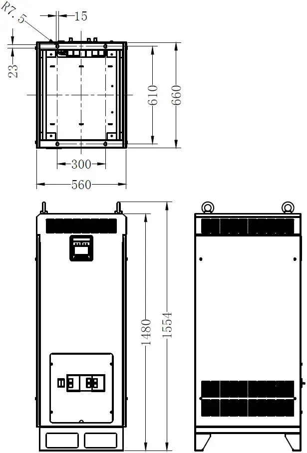
| Dimension(LxWxH) | 660x560x1554mm | |
| Net Weight | 270Kg | |
Environmental parameters:
| Operating temperature | -25℃ ~ 50℃★ |
| Noise | < 65Db (1m) |
| Enclosure | IP20 |
| Relative humidity range | 0 ~ 95%(N.C.) |
| Altitude | 5000m (Derating above1500m)★ |
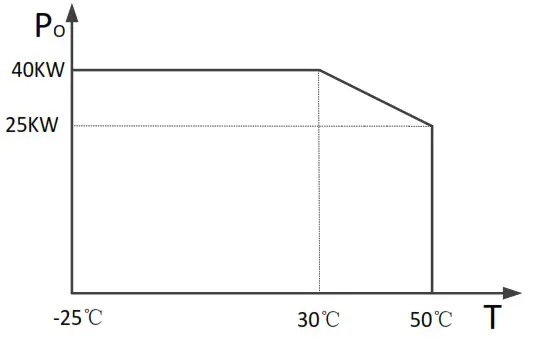
★ Instruction for inverter derating
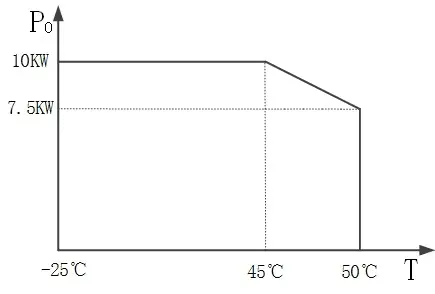
- Temperature derating for TP10KTP10KBTP20KTP20KBTP30KTP30KB:
For each increase of 1 above 45, the output power is reduced by 5% of the rated power.
TP10K, TP10KB TP20K, TP20KB
 TP30K, TP30KB
- Temperature derating for TP40K, TP40KB:
For each increase of 1 above 30, the output power is reduced by 750W.
- Altitude derating:
For each increase of 500m above 1500m, the output power is reduced by 5% of the rated power.
TP10K, TP10KB TP20K, TP20KB
 TP30K, TP30KB
 TP40K, TP40KB
 TP20K, TP20KB
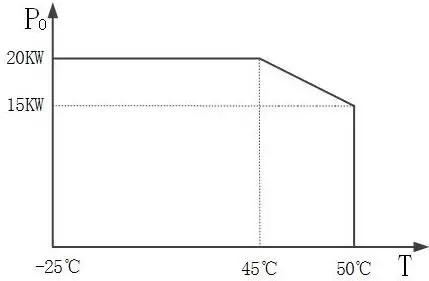 TP30K, TP30KB
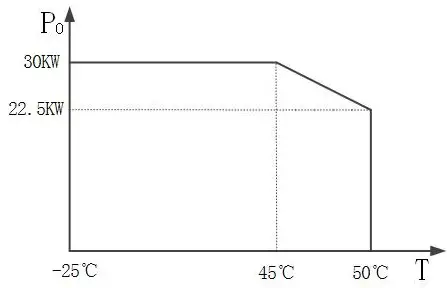
 TP20K, TP20KB
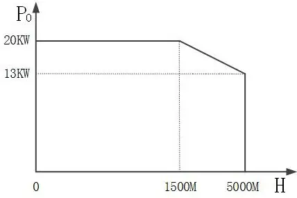 TP30K, TP30KB
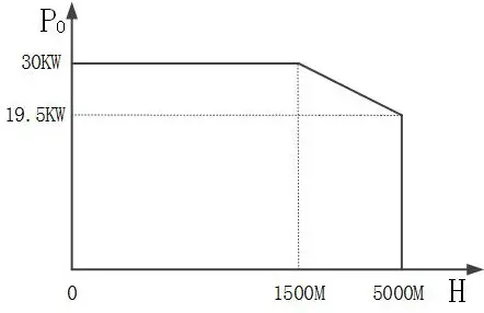 TP40K, TP40KB
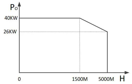
Annex 1 Disclaimer
This warranty does not apply under the following conditions:
- Damage from improper use or use in an unsuitable environment.
- Load or utility current, voltage, or power exceeds the rated value of the inverter.
- Damage caused by the ambient temperature exceeds the limit working environment temperature.
- The accident was caused by disobeying the marks or manuals of the inverter, such as electric arc, fire, and explosion.
- User disassembly or attempted to repair the inverter without permission.
- Damage caused by force majeure.
- Damage caused during transportation or loading/unloading.
Annex 2 Mechanical Dimension Diagram
- TP10K, TP10KB

- TP20K, TP20KB

- TP30K, TP30KB

- TP40K, TP40KB

Any changes without prior notice! Version number: V2.1 36
HUIZHOU EPEVER TECHNOLOGY CO., LTD.
Beijing Tel: +86-10-82894896/82894112
Huizhou Tel: +86-752-3889706
E-mail: [email protected]
Website: www.epever.com


