![]() NPower Series
NPower Series
Pure Sine Wave Inverter
User Manual
Important Safety Instructions
Please reserve this manual for future review.
This manual contains all the instructions about safety, installation, and operation for the NPower series pure sine wave inverter (hereinafter referred to as the inverter).
- Explanation of symbols
To enable the user to use the product efficiently, as well as to ensure personal and property safety, this manual provides related information and emphasizes the following symbols.
Please read the related words carefully when you encounter the following symbols in the manual.
TIP:
Indicates any practical advice for reference. IMPORTANT:
Indicates a critical tip during the operation, if ignored, may cause the device to run in error. CAUTION:
Indicates potential hazards, if not avoided, may cause the device damaged. WARNING:
Indicates the danger of electric shock, if not avoided, would cause casualties. WARNING HOT SURFACE:
Indicates the risk of high temperature, if not avoided, would cause scalds. Read the user manual carefully before any operation. WARNING: The entire system should be installed by professional and technical personnel.
 - Requirements for professional and technical personnel
 Professionally trained; Familiar with related safety specifications for the electrical system; Read the entire user manual to get related safety cautions.
 - Professional and technical personnel is allowed to do Install the inverter to the specified location; Test-run before installation; Operate and maintain the inverter.
- General installation notes IMPORTANT:: When receiving the inverter, please firstly check if there is any damage occurred in transportation, if find any problem, please contact the transportation company or our company in time. CAUTION: Follow the instructions before placing or moving the inverter. CAUTION: Make sure there isn’t any arc danger in the operation area before installation. CAUTION: Inverter input is recommended to connect to the battery, the minimum capacity of the battery (expressed in AH) should be calculated in the following way: 5 times the rated power of the inverter/battery voltage. WARNING: Keep the inverter out of children’s touch. WARNING: It’s an off-grid inverter, do not connect the AC output terminals to the utility or electrical source, otherwise, the inverter may be damaged. WARNING: The inverter can be used singly, in parallel connection, or in series will damage the inverters.
- Safety cautions for mechanical installation WARNING: Before installation, must make sure the inverter has no electrical connection. WARNING: Ensure the heat dissipation space for the inverter installation, and do not install the inverter in humid, greasy, flammable, explosive, dust accumulative, or other severe environments.
- Safety cautions for electrical connection CAUTION: Check if all the wiring connections are tight, to avoid the danger of heat accumulation due to a loose connection. CAUTION: The protective grounding must be connected to the ground. The cross-section of the wire should not be less than 4mm 2. CAUTION: Connect the DC input according to the requirement strictly. The power inverter has a relatively wide input range, but too high or too low input may cause problems or even destroy the inverter. CAUTION: The wire connecting the battery and inverter should be shorter than 3m, and the current density should be less than 5A/mm while the output of the inverter is fully loaded. If the wire is longer than 3m, the current density should be reduced. CAUTION: A fuse or breaker should be used between the battery and inverter; the value of the fuse or breaker should be twice the inverter-rated input current. CAUTION: DO NOT put the inverter close to the flooded lead-acid battery because the sparkle in the terminals may ignite the hydrogen released by the battery. WARNING: The output is forbidden to connect other power sources or utilities, otherwise the inverter will be damaged. The inverter must be off when connecting the load. WARNING: Do not directly connect the battery charger or similar devices to the input terminal of the inverter.
- Safety cautions for inverter operation WARNING HOT SURFACE: Do not touch it when the inverter is working, its surface may become very hot. Keep away from the material or device which may suffer from high temperatures. CAUTION: Do not open the inverter to operate when it is working. WARNING: The AC output with high voltage during the inverter operation, so do NOT touch the connection point, it may cause danger.
- The dangerous operations would cause an electric arc, fire, or explosion
• Touching the wire end which hasn’t been insulation treated may cause electriferous.
• Touch the wiring copper row, terminals, or internal devices which may causeelectriferous.
• The power cable connection is loose.
• Screw or other spare parts inadvertently falls into the inverter.
• Incorrect operation by untrained non-professional or technical personnel. WARNING: Once an accident occurs, must be handled by professional and technical personnel. Any incorrect operation would cause a more serious accident. - Safety cautions for stopping the inverter
• After the inverter stop working for ten minutes, the internal conductive devices could be touched.
• The inverter can be restarted after removing the faults, which may affect its safety performance.
• No maintenance parts in the inverter, if any maintenance service is required, please contact our after-sales service personnel. WARNING: Do NOT touch or open the case after the device is powered off within ten mins. - Safety cautions for inverter maintenance
• Testing equipment is recommended to check the inverter without voltage or current;
• When conducting electrical connection and maintenance work, one must post temporary warning sign or put up barriers, to prevent unrelated personnel from entering the electrical connection or maintenance area.
• Improper maintenance operation to the inverter may cause personal injury or equipment damage.
• To prevent electrostatic damage, recommend to wear an antistatic wrist strap or avoid unnecessary contact with the circuit board.
 Read the user manual carefully before any operation.
Overview
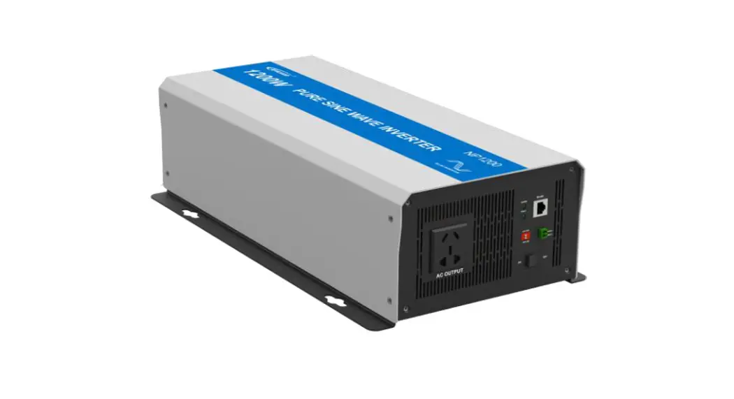
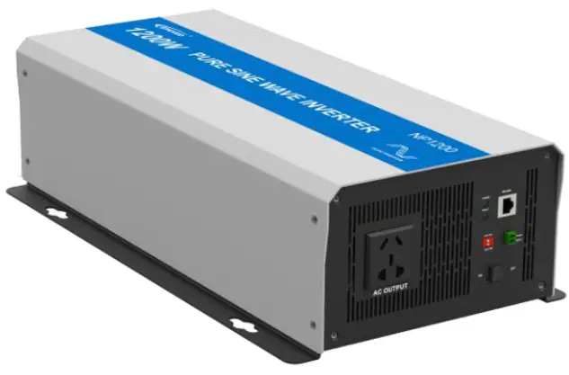
NPower series is a kind of pure sine wave inverter that can convert 12/24/48VDC to 220/230Vac. It is based on full digital and intelligent design, it adopts advanced SPWM technology, voltage, and current double closed-loop controlled and completely isolated inverter technology, such as to ensure the product with high-quality electrical parameters, the stronger ability to resist impact load, the input surge prevention design at the same time.meet the special requirements of lithium battery surge limit, to ensure the safety and function of the inverter running and reliability.
The case is designed with a galvanized board, which has the advantages of high strength and corrosion resistance.
This product has the characteristics of high reliability, high efficiency, simple appearance, complete protection function, easy installation, and easy operation. It is suitable for AC loads of household appliances, power tools, industrial equipment, electronic audio and video, and solar photovoltaic power generation system, such as vehicle inverter application systems, solar RV, solar households, solar yachts,s and solar power stations.
Features:
- Adoption of advanced SPWM technology, pure sine wave output
- Adopt voltage and current double closed-loop control to enhance the load capacity
- The input and output adopt completely isolated inverter technology with high reliability
- The input adopts an anti-surge design to meet the special requirements of surge limitation of the lithium battery and avoid dangerous surge current generated by the connection of startup.
- Low output harmonic distortion(THD≤3%)
- The AC output adopts excellent EMC design to prevent interference with connected equipment
- Output voltage 220/230VAC and frequency 50/60Hz optional
- Extensive protections: input reverse polarity, input overvoltage, input low voltage, output overload, short circuit, overheating.
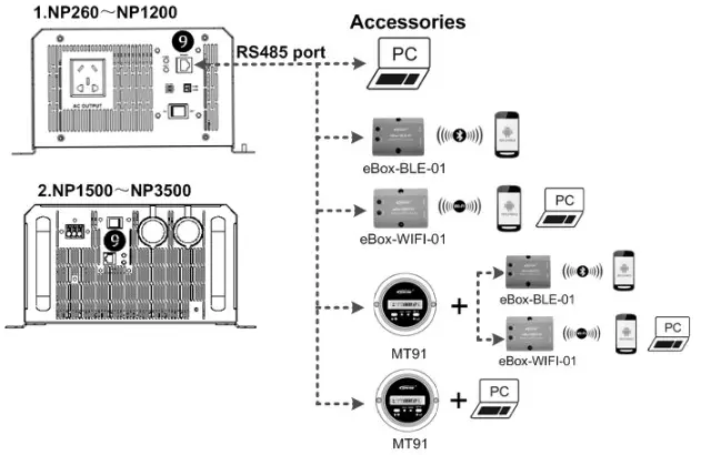
- OperRS485 port can connect the communication module, realize remote start/stop inverter and monitor the running status via the APP or PC software. Set the input low voltage and low voltage reconnect voltage via the APP or PC software
- Set the inverter’s ID via the APP or PC software to monitor several inverters.
- The case is designed with galvanized board, with high strength and strong corrosion resistance
- Chinese dual socket, Australia/New Zealand, European, Universal, Terminal selectable
- The remote meter is selectable
- Easy maintenance and repair
Characteristics
- NP260~NP1200

- NP1500~NP3500

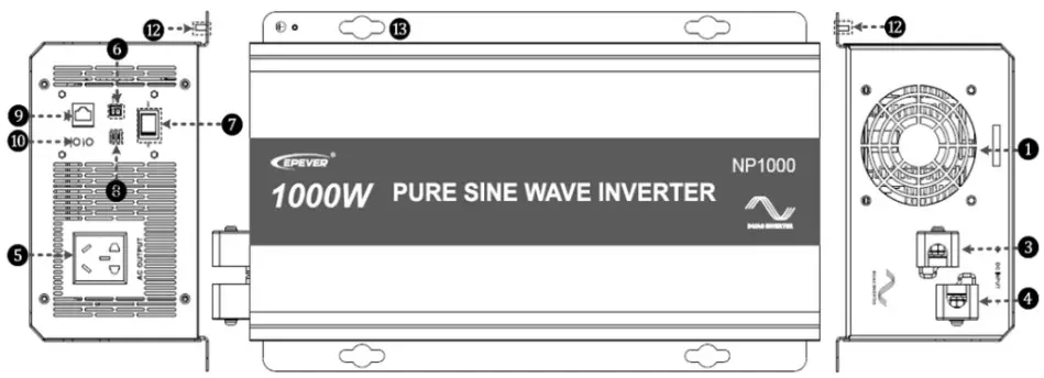
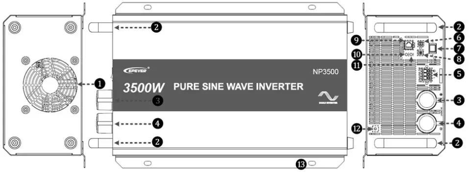
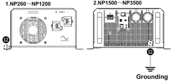
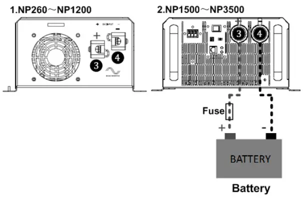
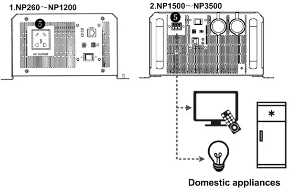
| 1 Ventilation fan¹ 2 Handle 3 DC input terminal positive 4 DC input terminal negative 5 AC outlet² 6 The external switch connection point 7 AC output switch | 8 Mode switch(3) 9 RS485 communication port(4) 10 Working indicator(green)(5) 11 Fault indicator(red)(5) 12 Grounding terminal 13 Mounting hole size |
(1) Ventilation fan
- The cooling fan will be automatically turned on if the inverter could reach any condition down below.
- Heat sink temperature is higher than 45℃
- Internal temperature is higher than 45℃
- The output power is higher than the same power, see the below table:
| Models | Instruction |
| NP260-12(X); NP260-22(X) NP400-12(X); NP400-22(X) NP600-12(X); NP600-22(X) NP800-12(X) NP1000-22(X) NP1200-12(X); NP1200-22(X) | The internal temperature is higher than 10℃, and the output power is higher than half of the continuous output power of 25℃. |
| NP2000-42(T) NP2500-22(T) NP3000-22(T);NP3000-42(T) NP3500-42(T) | internal temperature is higher than 10℃, and the output power is higher than 1000W |
“X” is a Chinese dual socket, Australia/New Zealand, E-European, M- Universal.
- The cooling fan will be automatically turned off when the inverter reaches all the conditions down below.
- The heat sink temperature is lower than40℃
- Internal temperature is lower than 40℃
- The output power is lower than the same power, see the below table:
| Models | Instruction |
| NP260-12(X); NP260-22(X) | The output power is lower than 80W |
| NP400-12(X); NP400-22(X) | The output power is lower than 150W |
| NP600-12(X); NP600-22(X) | The output power is lower than 200W |
| NP800-12(X) | The output power is lower than 300W |
| NP1000-22(X) | The output power is lower than 400W |
| NP1200-12(X); NP1200-22(X) NP2000-42(T) | The output power is lower than 500W |
| NP2500-22(T) NP3000-22(T);NP3000-42(T) NP3500-42(T) | The output power is lower than 800W |
“X” is a Chinese dual socket, Australia/New Zealand, E-European, M- Universal.
(2) AC outlet
Universal:
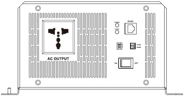
Chinese dual socket:
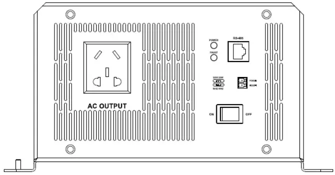
Australia/New Zealand:
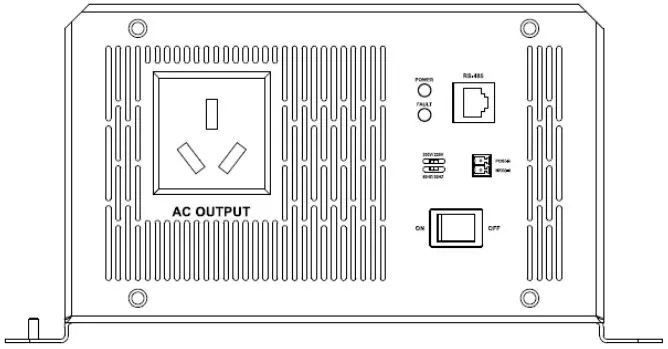
European:
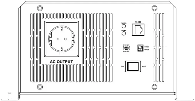
Terminal:
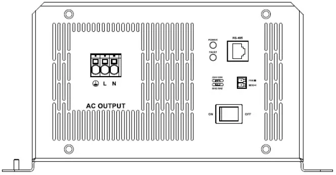
(3)Mode switch
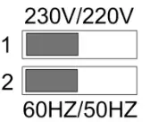
When the switch of number 1 is on the 230V side, the output voltage is 230VAC, otherwise is 220VAC.
When the switch of number 2 is on the 60Hz side, the output frequency is 60Hz, otherwise is 50Hz.![]() CAUTION: Both the output frequency and voltage change availability after restarting the inverter.
CAUTION: Both the output frequency and voltage change availability after restarting the inverter.![]() WARNING: DO NOT turn ON/OFF the mode switch when the inverter is working.
WARNING: DO NOT turn ON/OFF the mode switch when the inverter is working.
(4)RS485 communication port
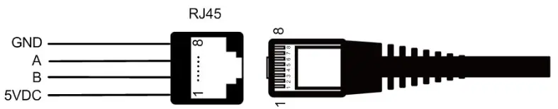
The RJ45 port pin definition is shown below:
| 1 | 5VDC | 5 | RS-485-A |
| 2 | 5VDC | 6 | RS-485-A |
| 3 | RS-485-B | 7 | GND |
| 4 | RS-485-B | 8 | GND |
(5)LED indicator and buzzer
| Working indicator | Fault indicator | Buzzer | Status |
| Green super flashing | Red off | No sounding | Standby |
| Green on solid | Red off | No sounding | Output is normal |
| Green slowly flashing | Red off | Sounding | Input under voltage |
| Green fast flashing | Red off | Sounding | Input over voltage |
| Green on solid | Red on solid | Sounding | Over Temperature |
| Green off | Red fast flashing | Sounding | load short circuit |
| Green on solid | Red slowly flashing | Sounding | Overload |
| Green off | Red off | Sounding | Output voltage abnormal |
Designations of models
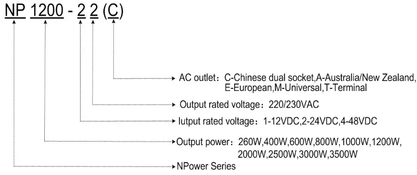
| Models | Input rated voltage | Output rated voltage | Output power |
| NP260-12(X) | 12VDC | 220/230VAC | 260W |
| NP260-22(X) | 24VDC | ||
| NP400-12(X) | 12VDC | 400W | |
| NP400-22(X) | 24VDC | ||
| NP600-12(X) | 12VDC | 600W | |
| NP600-22(X) | 24VDC | ||
| NP800-12(X) | 12VDC | 800W | |
| NP1000-22(X) | 24VDC | 1000W | |
| NP1200-12(X) | 12VDC | 1200W | |
| NP1200-22(X) | 24VDC | ||
| NP2000-42(T) | 48VDC | 2000W | |
| NP2500-22(T) | 24VDC | 2500W | |
| NP3000-22(T) | 24VDC | 3000W | |
| NP3000-42(T) | 48VDC | ||
| NP3500-42(T) | 48VDC | 3500W |
“X” is a Chinese dual socket, Australia/New Zealand, European, M- Universal.
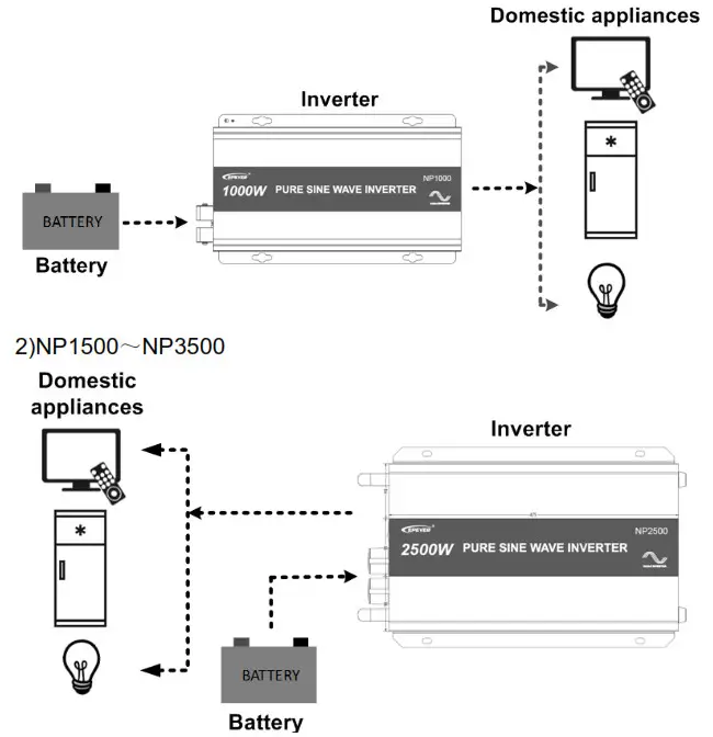
The schematic diagram for connections
- NP260~NP1200
 CAUTION: Connecting the DC input directly to the battery port is recommended, DO NOT connect to the battery terminal of the controller. Otherwise, the charging frequency spikes of the controller may lead to over-voltage protection of the inverter.
Installation instructions
5.1 General installation notes
- Please read the manual carefully to get familiar with the installation steps before installation.
- Be very careful when installing the batteries, especially flooded lead-acid batteries. Please wear eye protection, and have fresh water available to rinse if any contact with battery acid.
- Keep the battery away from any metal objects, which may cause a short circuit of the battery.
- Loose connections and corroded wires may result in high heat that can melt wire insulation, burn surrounding materials, or even cause a fire. Ensure tight connections and use cable clamps to secure cables and prevent them from swaying in motion.
- Select the system connection cables according to the current density no higher than 5A/mm2. (In accordance with the National Electrical Code Article 690, NFPA70).
- For outdoor installation, keep out of the direct sunshine and rain infiltration.
- High voltage still exists inside the inverter after turning off the switch, do not open or touch the internal devices, wait ten minutes before conducting related operations.
- Please do not install the inverter in humid, greasy, flammable, explosive, dust accumulative, or other severe environments.
- AC output is a high voltage, please do not touch the wiring connection.
- When the fan is working, please do not touch it to avoid injury.
5.2Wire size &breaker
Wiring and installation mode should comply with national and local electrical code requirements.
- Wire, terminals, and breaker selection for battery
| Models | Battery wire size | Terminal | Breaker |
| NP260-12(X) | 6mm2/10AWG | RNB5.5-6 | DC/2P—40A |
| NP260-22(X) | 4mm2/12AWG | RNB5.5-6 | DC/2P—20A |
| NP400-12(X) | 10mm2/8AWG | RNB8-6S | DC/2P—63A |
| NP400-22(X) | 6mm2/10AWG | RNB5.5-6 | DC/2P—32A |
| NP600-12(X) | 16mm2/6AWG | RNB14-8 | DC/2P—80A |
| NP600-22(X) | 6mm2/10AWG | RNB8-8 | DC/2P—40A |
| NP800-12(X) | 25mm2/4AWG | RNB22-6L | DC/2P—125A |
| NP1000-22(X) | 16mm2/6AWG | RNB14-6L | DC/2P—63A |
| NP1200-12(X) | 25mm2/4AWG | RNB22-6L | DC/2P—125A |
| NP1200-22(X) | 16mm2/6AWG | RNB14-6L | DC/2P—63A |
| NP2000-42(T) | 16mm2/6AWG | RNB14-10 | DC/2P—63A |
| NP2500-22(T) | 35mm2/2AWG | RNB38-10 | DC—100A (2P in parallel) |
| NP3000-22(T) | 50mm2/1/0AWG | RNB38-10 | DC—100A (2P in parallel) |
| NP3000-42(T) | 25mm2/4AWG | RNB22-10 | DC/2P—100A |
| NP3500-42(T) | 25mm2/4AWG | RNB22-10 | DC/2P—125A |
“X” is a Chinese dual socket, Australia/New Zealand, E-European, M- Universal.
- Wire and breaker selection for AC output
| Models | Wire size | Breaker |
| NP2000-42(T) | 1.5mm2/16AWG | AC/2P—10A |
| NP2500-22(T) | 2.5mm2/14AWG | AC/2P—10A |
| NP3000-22(T) | 2.5mm2/14AWG | AC/2P—16A |
| NP3000-42(T) | 2.5mm2/14AWG | AC/2P—16A |
| NP3500-42(T) | 2.5mm2/14AWG | AC/2P—16A |
![]() IMPORTANT: The wire size and terminal are for reference only, use thicker wires to lower the voltage drop and improve the system performance when the distance between the inverter and batter is far.
IMPORTANT: The wire size and terminal are for reference only, use thicker wires to lower the voltage drop and improve the system performance when the distance between the inverter and batter is far.![]() IMPORTANT: The above wire size and circuit breaker size are for recommendation only, please choose a suitable wire and circuit breaker according to the practical situation.
IMPORTANT: The above wire size and circuit breaker size are for recommendation only, please choose a suitable wire and circuit breaker according to the practical situation.
5.3 Mounting
Installation steps:
Step1:Professional personnel read this manual carefully.
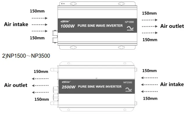
Step2:Determination of installation location and heat-dissipation space.![]() Important: The inverter shall be installed in a place with sufficient airflow through the dissipation pad of the inverter and a minimum clearance of 150mm from the upper and lower edges of the inverter to ensure natural thermal convection.
Important: The inverter shall be installed in a place with sufficient airflow through the dissipation pad of the inverter and a minimum clearance of 150mm from the upper and lower edges of the inverter to ensure natural thermal convection.![]() CAUTION: The inverter shall be cooling through housing if installed in a closed box.
CAUTION: The inverter shall be cooling through housing if installed in a closed box.
- NP260~NP1200

Step3:Wiring![]() WARNING: The AC equipment shall be determined by the continuous output power of the inverter, but the surge power must be lower than the instantaneous surge power of the inverter.
WARNING: The AC equipment shall be determined by the continuous output power of the inverter, but the surge power must be lower than the instantaneous surge power of the inverter.![]() CAUTION: The switch of the inverter is off before wiring.
CAUTION: The switch of the inverter is off before wiring.![]() CAUTION: DO NOT close the circuit breaker or fuse and make sure that the leads of the “+” and “-” poles are connected correctly while wiring the inverter.
CAUTION: DO NOT close the circuit breaker or fuse and make sure that the leads of the “+” and “-” poles are connected correctly while wiring the inverter.
CAUTION: A fuse whose current is 1.25 to 2 times the rated current of the inverter, must be installed on the battery side at a distance from the battery not greater than 150mm.
Wiring order:
- Ground

- Battery

- AC loads

- Accessories

![]() CAUTION: Disconnect the system in the reverse order❹❸❷❶.
CAUTION: Disconnect the system in the reverse order❹❸❷❶.
Step4:Power on the inverter
- Switch on the input breaker or the fuse between the inverter and the battery.
- Turn on the power switch to start the inverter, the green indicator is on solid, and the AC output is normal.
- Turn on the load one by one and check the operation status of both the inverter and load.
CAUTION: If there are different types of loads, it is suggested that turn on the loads with higher startup current first, such as television, then after the loads work stably, turn on the loads with lower startup current, such as an incandescent lamp. - If the fault indicator is red and the buzzer alarms when turning on the inverter, please switch off the loads and inverter immediately. Refer to chapter 7 Troubleshooting. After troubleshooting, please follow the above steps and operate again.
Protection
- Input reverse polarity protection
The electronic circuit works to protect the inverter from damage while the input reverses polarity. And the inverter will get right while the input is right. - Input overvoltage protection
- Input overvoltage protection
Models Protection value Default User-defined Phenomenon NP***-1* 16V<Ui<16.2V 16V 15.5~16.2V The output is OFF after 5s Green indicator fast flashing Buzzer sounds NP***-2* 32V<Ui<32.2V 32V 31~32.2V NP***-4* 64V<Ui<64.4V 64V 62~64.4V NP***-1* Ui≥16.2V — — The output is OFF immediately Green indicator fast flashing
Buzzer soundsNP***-2* Ui≥32.2V — — NP***-4* Ui≥64.4V — — - Input overvoltage recovers protection
Models Recover value Default User-defined Phenomenon NP***-1* Ui≤14.5V 14.5V 14~15V Green indicator on solid Output is ON
NP***-2* Ui≤29V 29V 28~30V NP***-4* Ui≤58V 58V 56~60V 3) Low voltage protection
- Low voltage protection
Models Protection value Default User-defined Phenomenon NP***-1* 10.5V<Ui<10.8V 10.8V 10.5~11.3V The output is OFF after 5s Green indicator slowly flashes Buzzer sounds NP***-2* 21V<Ui<21.6V 21.6V 21~22.6V NP***-4* 42V<Ui<43.2V 43.2V 42~45.2V NP***-1* Ui≤10.8V — — The output is OFF immediately Green indicator slowly flashes Buzzer sounds NP***-2* Ui≤21.6V — — NP***-4* Ui≤32.2V — — - Low voltage recovery protection
4)Overload protectionS=1.25Pe① (S: Output power; Pe: Rated power) The output is OFF after the 60s Red indicator slowly flashes Buzzer sounds S=1.5Pe① (S: Output power; Pe: Rated power) The output is OFF after 10s Red indicator slowly flashes Buzzer sounds S=1.8Pe① (S: Output power; Pe: Rated power) The output is OFF after 3s Red indicator slowly flashes Buzzer sounds ① When the overload protection is activated, the AC output would auto-recover three times(the first time delay 5s, the second time delay for 10s, and the third time delay of 15s). After then the AC output would not auto-recover after restarting the inverter.
5)Load short circuit protectionPhenomenon Instruction The output is OFF immediately Red indicator slowly flashes Buzzer sounds When the load short circuit protection is activated, the AC output would auto-recover three times(the first time delay of 5s, the second time delay of 10s, and the third time delay of 15s). After then the AC output would not auto-recover after restarting the inverter. 6)OverTemperture Protection
Phenomenon Instruction Inverter turns OFF The heat sink or internal temperature is higher than some values. Inverter turns ON The heat sink or internal temperature is lower than some values.
Troubleshooting
![]() WARNING: DO NOT try to repair or maintain the inverter by yourself, it may cause danger.
WARNING: DO NOT try to repair or maintain the inverter by yourself, it may cause danger.
| Phenomenon | Possible reasons | Troubleshooting |
| Green indicator slowly flashing Buzzer sounds | DC input voltage under voltage | Measure the DC input voltage if the voltage is lower than10.8/21.6/43.2V. Adjust the input voltage to restore normally. |
| Green indicator fast flashing Buzzer sounds | DC input voltage overvoltage | Measure the DC input voltage if the voltage is lower than16/32/64V. Adjust the input voltage to restore normally. |
| Red indicator slowly flashing Buzzer sounds | Overload | • Reduce the number of the AC load • Restart the inverter |
| Red indicator fast flashing Buzzer sounds | Short circuit | • Check carefully the load connection, and clear the fault. • Restart the inverter |
| Red and green indicators on the solid Buzzer sounds | Over Temperature | Improve ventilation quality, do NOT block the vent, reduce the temperature around the power supply, and restart the device after the temperature drops, if still not working, please derate the power for use. |
Maintenance
The following inspections and maintenance tasks are recommended at least two times per year for the best performance.
- Make sure no block on airflow around the inverter. Clear up any dirt and fragments on the radiator.
- Check all the naked wires to make sure the insulation is not damaged for serious solarization. Frictional wear, dryness, insects or rats, etc. Repair or replace some wires if necessary.
- Check and confirm that indicator and display are consistent with required. Pay attention to any troubleshooting or error indication. Take corrective action if necessary.
- Confirm that all the terminals have no corrosion, insulation damage, high temperature, or burnt/discolored sign, tighten terminal screws to the suggested torque.
- Check for dirt, nesting insects, and corrosion. If so, clear up in time.
- Check and confirm that the lightning arrester is in good condition. Replace a new one in time to avoid damaging the inverter/charger and even other equipment.
![]() WARNING: Risk of electric shock!
WARNING: Risk of electric shock!
Risk of electric shock! Before the above operations, make sure that all the power is turned off, and the electricity in the capacitances is completely discharged, then follow the corresponding inspections and operations.
Technical Specifications
| Item | NP260-12 | NP260-22 |
| Output Continuous Power | 260W@25℃;260W@45℃ | |
| Surge Power | 400W | |
| Output Voltage | 220/230VAC(-8%~+3%) | 220/230VAC(±3%) |
| Output Frequency | 50/60±0.2% | |
| Output Wave | Pure Sine Wave | |
| Output distortion THD | THD≤3%(Resistive load) | |
| Load Power Factor | 0.2~1(VA≤Continuous output power) | |
| Rated input voltage | 12VDC | 24VDC |
| Input voltage range | 10.8~16VDC | 21.6~32VDC |
| output efficiency of80% rated power① | 81% | 84% |
| Max. Rated Efficiency② | 79% | 82% |
| Max. Efficiency | 89%(80W) | 90%(100W) |
| No-load Current | <0.4A | <0.3A |
| Rs485 Com. Port | 5VDC/200mA | |
| Environmental Parameters | ||
| Binding Post | M6 | |
| Overall dimension | 365×212×97mm(L×W×H) | |
| Mounting Dimension | 220×193mm | |
| Mounting hole size | Φ7mm | |
| Weight | 6.4kg | 6.3kg |
① Load power is 80% continuous output power(25℃)
② Load power is continuous output power (25℃)
| Item | NP400-12 | NP400-22 |
| Output Continuous Power | 400W@25℃;350W@45℃ | |
| Surge Power | 700W | |
| Output Voltage | 220/230VAC(-8%~+3%) | 220/230VAC(±3%) |
| Output Frequency | 50/60±0.2% | |
| Output Wave | Pure Sine Wave | |
| Output distortion THD | THD≤3%(Resistive load) | |
| Load Power Factor | 0.2~1(VA≤Continuous output power) | |
| Rated input voltage | 12VDC | 24VDC |
| Input voltage range | 10.8~16VDC | 21.6~32VDC |
| output efficiency of 80% rated power① | 81% | 85% |
| Max. Rated Efficiency② | 79% | 84% |
| Max. Efficiency | 90%(100W) | 91%(100W) |
| No-load Current | <0.5A | <0.3A |
| Rs485 Com. Port | 5VDC/200mA | |
| Environmental Parameters | ||
| Binding Post | M6 | |
| Overall dimension | 386×215×99mm | |
| Mounting Dimension | 230×196mm | |
| Mounting hole size | Φ7mm | |
| Weight | 6.3kg | 7.9kg |
①Load power is 80% continuous output power(25℃)
②Load power is continuous output power (25℃)
| Item | NP600-12 | NP600-22 |
| Output Continuous Power | 600W@25℃; 500W@45℃ | |
| Surge Power | 1000W | |
| Output Voltage | 220/230VAC(-8%~+3%) | 220/230VAC(±3%) |
| Output Frequency | 50/60±0.2% | |
| Output Wave | Pure Sine Wave | |
| Output distortion THD | THD≤3%(Resistive load) | |
| Load Power Factor | 0.2~1(VA≤Continuous output power) | |
| Rated input voltage | 12VDC | 24VDC |
| Input voltage range | 10.8~16VDC | 21.6~32VDC |
| output efficiency of 80% rated power① | 81% | 85% |
| Max. Rated Efficiency② | 80% | 83% |
| Max. Efficiency | 89%(200W) | 92%(160W) |
| No-load Current | <0.6A | <0.4A |
| Rs485 Com. Port | 5VDC/200mA | |
| Environmental Parameters | ||
| Binding Post | M8 | |
| Overall dimension | 428×243×121mm | |
| Mounting Dimension | 260×220mm | |
| Mounting hole size | Φ9mm | |
| Weight | 10.4kg | 10.1kg |
①Load power is 80% continuous output power(25℃)
②Load power is continuous output power (25℃)
| Item | NP800-12 |
| Output Continuous Power | 800W@25℃;800W@45℃ |
| Surge Power | 1600W |
| Output Voltage | 220/230VAC (-8%~+3%) |
| Output Frequency | 50/60±0.2% |
| Output Wave | Pure Sine Wave |
| Output distortion THD | THD≤3%(Resistive load) |
| Load Power Factor | 0.2~1(VA≤Continuous output power) |
| Rated input voltage | 12VDC |
| Input voltage range | 10.8~16VDC |
| output efficiency of 80% rated power① | 83% |
| Max. Rated Efficiency② | 81% |
| Max. Efficiency | 92%(100W) |
| No-load Current | <0.6A |
| Rs485 Com. Port | 5VDC/200mA |
| Environmental Parameters | |
| Binding Post | M6 |
| Overall dimension | 475×268×139mm |
| Mounting Dimension | 270×245mm |
| Mounting hole size | Φ9mm |
| Weight | 13.3kg |
①Load power is 80% continuous output power(25℃)
②Load power is continuous output power (25℃)
| Item | NP1000-22 |
| Output Continuous Power | 1000W@25℃;800W@45℃ |
| Surge Power | 1600W |
| Output Voltage | 220/230VAC(±3%) |
| Output Frequency | 50/60±0.2% |
| Output Wave | Pure Sine Wave |
| Output distortion THD | THD≤3%(Resistive load) |
| Load Power Factor | 0.2~1(VA≤Continuous output power) |
| Rated input voltage | 24VDC |
| Input voltage range | 21.6~32VDC |
| output efficiency of 80% rated power① | 85% |
| Max. Rated Efficiency② | 82% |
| Max. Efficiency | 92%(200W) |
| No-load Current | <0.4A |
| Rs485 Com. Port | 5VDC/200mA |
| Environmental Parameters | |
| Binding Post | M6 |
| Overall dimension | 475×268×139mm |
| Mounting Dimension | 270×245mm |
| Mounting hole size | Φ9mm |
| Weight | 12.7kg |
①Load power is 80% continuous output power(25℃)
②Load power is continuous output power (25℃)
| Item | NP1200-12 | NP1200-22 |
| Output Continuous Power | 1200W@25℃;1000W@45℃ | |
| Surge Power | 2000W | |
| Output Voltage | 220/230VAC(-8%~+3%) | 220/230VAC(±3%) |
| Output Frequency | 50/60±0.2% | |
| Output Wave | Pure Sine Wave | |
| Output distortion THD | THD≤3%(Resistive load) | |
| Load Power Factor | 0.2~1(VA≤Continuous output power) | |
| Rated input voltage | 12VDC | 24VDC |
| Input voltage range | 10.8~16VDC | 21.6~32VDC |
| output efficiency of 80% rated power① | 81% | 85% |
| Max. Rated Efficiency② | 78% | 84% |
| Max. Efficiency | 92%(200W) | 93%(300W) |
| No-load Current | <0.6A | <0.4A |
| Rs485 Com. Port | 5VDC/200mA | |
| Environmental Parameters | ||
| Binding Post | M6 | |
| Overall dimension | 511×268×139mm | |
| Mounting Dimension | 300×245mm | |
| Mounting hole size | Φ9mm | |
| Weight | 15.7kg | 15.3kg |
①Load power is 80% continuous output power(25℃)
②Load power is continuous output power (25℃)
| Item | NP2000-42 |
| Output Continuous Power | 2000W@25℃;2000W@45℃ |
| Surge Power | 4000W |
| Output Voltage | 220/230VAC(±3%) |
| Output Frequency | 50/60±0.2% |
| Output Wave | Pure Sine Wave |
| Output distortion THD | THD≤3%(Resistive load) |
| Load Power Factor | 0.2~1(VA≤Continuous output power) |
| Rated input voltage | 48VDC |
| Input voltage range | 43.2~64VDC |
| output efficiency of 80% rated power① | 89% |
| Max. Rated Efficiency② | 87% |
| Max. Efficiency | 93%(500W) |
| No-load Current | <0.3A |
| Rs485 Com. Port | 5VDC/200mA(Isolation) |
| Environmental Parameters | |
| Binding Post | M10 |
| Overall dimension | 486×313×145mm |
| Mounting Dimension | 350×292mm |
| Mounting hole size | Φ9mm |
| Weight | 20.7kg |
①Load power is 80% continuous output power(25℃)
②Load power is continuous output power (25℃)
| Item | NP2500-22 |
| Output Continuous Power | 2500W@25℃;2500W@45℃ |
| Surge Power | 5000W |
| Output Voltage | 220/230VAC(-6%~+3%) |
| Output Frequency | 50/60±0.2% |
| Output Wave | Pure Sine Wave |
| Output distortion THD | THD≤3%(Resistive load) |
| Load Power Factor | 0.2~1(VA≤Continuous output power) |
| Rated input voltage | 24VDC |
| Input voltage range | 21.6~32VDC |
| output efficiency of 80% rated power① | 89% |
| Max. Rated Efficiency② | 87% |
| Max. Efficiency | 93%(500W) |
| No-load Current | <0.8A |
| Rs485 Com. Port | 5VDC/200mA |
| Environmental Parameters | |
| Binding Post | M10 |
| Overall dimension | 539×328×170mm |
| Mounting Dimension | 350×307mm |
| Mounting hole size | Φ9mm |
| Weight | 32.8kg |
①Load power is 80% continuous output power(25℃)
②Load power is continuous output power (25℃)
| Item | NP3000-22 | NP3000-42 |
| Output Continuous Power | 3000W@25℃;3000W@45℃ | |
| Surge Power | 6000W | |
| Output Voltage | 220/230VAC(-5%~+3%) | 220/230VAC(±3%) |
| Output Frequency | 50/60±0.2% | |
| Output Wave | Pure Sine Wave | |
| Output distortion THD | THD≤3%(Resistive load) | |
| Load Power Factor | 0.2~1(VA≤Continuous output power) | |
| Rated input voltage | 24VDC | 48VDC |
| Input voltage range | 21.6~32VDC | 43.2~64VDC |
| output efficiency of 80% rated power① | 88% | 90% |
| Max. Rated Efficiency② | 86% | 89% |
| Max. Efficiency | 94%(500W) | 94%(900W) |
| No-load Current | <0.8A | <0.5A |
| Rs485 Com. Port | 5VDC/200mA | 5VDC/200mA(Isolation) |
| Environmental Parameters | ||
| Binding Post | M10 | |
| Overall dimension | 639×393×175.5mm | 584×328×170mm |
| Mounting Dimension | 350×372mm | 350×307mm |
| Mounting hole size | Φ9mm | |
| Weight | 36.4kg | 28.4kg |
①Load power is 80% continuous output power(25℃)
②Load power is continuous output power (25℃)
| Item | NP3500-42 |
| Output Continuous Power | 3500W@25℃;3500W@45℃ |
| Surge Power | 7000W |
| Output Voltage | 220/230VAC(±3%) |
| Output Frequency | 50/60±0.2% |
| Output Wave | Pure Sine Wave |
| Output distortion THD | THD≤3%(Resistive load) |
| Load Power Factor | 0.2~1(VA≤Continuous output power) |
| Rated input voltage | 48VDC |
| Input voltage range | 43.2~64VDC |
| output efficiency of 80% rated power① | 90% |
| Max. Rated Efficiency② | 89% |
| Max. Efficiency | 93%(900W) |
| No-load Current | <0.5A |
| Rs485 Com. Port | 5VDC/200mA(Isolation) |
| Environmental Parameters | |
| Binding Post | M10 |
| Overall dimension | 564×353×175mm |
| Mounting Dimension | 350×332mm |
| Mounting hole size | Φ9mm |
| Weight | 32.2kg |
①Load power is 80% continuous output power(25℃)
②Load power is continuous output power (25℃)
Environmental Parameters
| Working Temperature | -20℃~+45℃(Full load) |
| Storage Temperature | -35℃~ +70℃ |
| Humidity | < 95%(N.C.) |
| Enclosure | IP20 |
| Altitude | <5000m (Derating to operate according to IEC62040 at a height exceeding 1000m) |
AnnexⅠDisclaimer
The warranty does not apply under the following conditions:
- Damage caused by improper use or use in an inappropriate environment.
- Battery voltage exceeds the input voltage limit of the inverter.
- Damage caused by the working environment temperature exceeding the rated range.
- Unauthorized dismantling or attempted repair.
- Damage occurred during transportation or handling.
- Damage caused by force majeure.
Any changes without prior notice! Version number: V1.1
![]() BEIJING EPSOLAR TECHNOLOGY CO., LTD.
BEIJING EPSOLAR TECHNOLOGY CO., LTD.
Tel: +86-10-82894896 / 82894112
Fax: +86-10-82894882
E-mail:[email protected]
Website: www.epever.co


