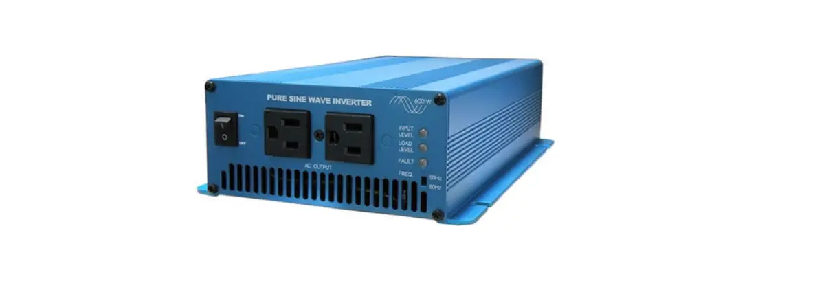
Power Bright IU Series Pure Sine Wave Inverter
Dear user: Thank you very much for choosing our product!
Important safety instructions
Please keep this manual for future reference This manual contains all safety, installation and operating instructions for the IU Series pure sine wave inverter (high frequency) (hereinafter referred to as “the Inverter”). Please read all instructions and precautions in the manual carefully before installation and use.
- Non-safety voltage exists inside the inverter. To avoid personal injury, users shall not disassemble the inverter themselves. Please contact our professional maintenance personnel for repair.
- Do not place the inverter within the reach of children.
- Do not install the inverter in harsh environments such as moist, oily, flammable or explosive, or heavily dusty areas.
- The AC output of the inverter is high voltage, so please do not touch the wiring terminals.
- The housing of the inverter is super hot when it is working. Do not touch it and keep away from materials or equipment affected by high temperature.
- Do not open the terminal protective cover when the inverter is working.
- Make sure to disconnect the fuse or circuit breaker near the terminals of the battery and AC output before installing and adjusting the wiring of the inverter.
- After installation, check whether all wiring is tightly connected to avoid the danger of heat accumulation due to loose connection.
- The inverter is off-grid. It is necessary to confirm that it is the only input device for load, and it is forbidden to use it in parallel with other input AC power to avoid damage.
- In order to ensure that users can protect their personal and property safety while using this product, relevant information is highlighted in the manual with following symbols. The following symbols in the manual indicate that you should read the relevant words carefully.
Warning: Electric shock that may damage devices or electrocution/injury if it is not avoided.
Caution: Potential dangers that may damage devices if they are not avoided.
Note: Important notices in operation that may trigger the device fault alarm if they are not performed.
Introduction
Product overview
Thanks to the full-digital intelligent control technology and voltage-current double closed-loop control algorithm adopted, IU Series pure sine wave inverter (high-frequency) has a fast dynamic response, high conversion efficiency, low harmonic component and stable operation. With idle mode, normal mode and energy saving mode optional, the IU Series can maximize battery energy saving based on application scenarios and requirements; Key components with high power density and long service life provide this IU Series with continuous long-time and full-power output. And comprehensive electronic protections keep the entire system safer and more stable; IU series is applicable to various off-grid systems that need to convert DC into AC, such as RV power supply system, on-board system, monitoring system, emergency lighting system, household power supply system, small-scale on-site power supply and occasions with high requirements for power quality.
Product features
- Full digital voltage-current double closed-loop control, in high response speed and reliability. Advanced SPWM technology for pure sine wave.
- Advanced wave-filter and current-limiting technology, with impact load such as large capacitive and inductive available.
- Various output sockets to satisfy customers in different countries and regions.
- High power density and long-life devices for product reliability.
- Output power factor up to 1, with full load power for long-term operation.
- Low no-load loss and standby loss, low total harmonic distortion (THD), and high conversion efficiency. Input under-voltage/overvoltage protection, input overload/short-circuit protection, device over-temperature protection, fan fault protection, etc.
- Intelligent air cooling control system for detecting the output of fan blocked control.
- Output voltage: 110/120 VAC, output frequency: 50/60 Hz (settable).
- AC output overload protector for safe and reliable operation.
- Excellent Electromagnetic Compatibility (EMC) for locations with high power quality requirements. Rs485 communication interface for various components.
- Dual USB interface output with maximum support of 5V2A.
- Electron Coupled Oscillator (ECO) for maximum electric power saving.
- Transistor-Transistor Logic (TTL) communication interface for external Bluetooth or display screen connection and interaction.
- External switch contact for remote control of the inverter via external mechanical switches or relays. Supported Bluetooth and available mobile APP to check the operation condition/real-time data and fault condition.
- Optional Controller Area Network (CAN) communication of RV-C.
Appearance and interface description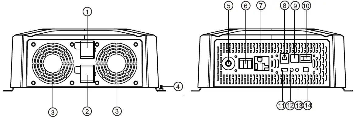
| S/N | Name | S/N | Name |
| 1 | Positive electrode of battery input | 8 | RS485 communication interface |
| 2 | Negative electrode of Battery input | 9 | USB interface |
| 3 | Cooling fan | 10 | ON/OFF/ECO mode switch |
| 4 | Input grounding terminal | 11 | TTL communication interface |
| 5 | Output overload protector | 12 | Running indicator |
| 6 | AC output terminal 1 | 13 | Fault indicator |
| 7 | AC output terminal 2 | 14 | External switch contact interface |
Dimension drawing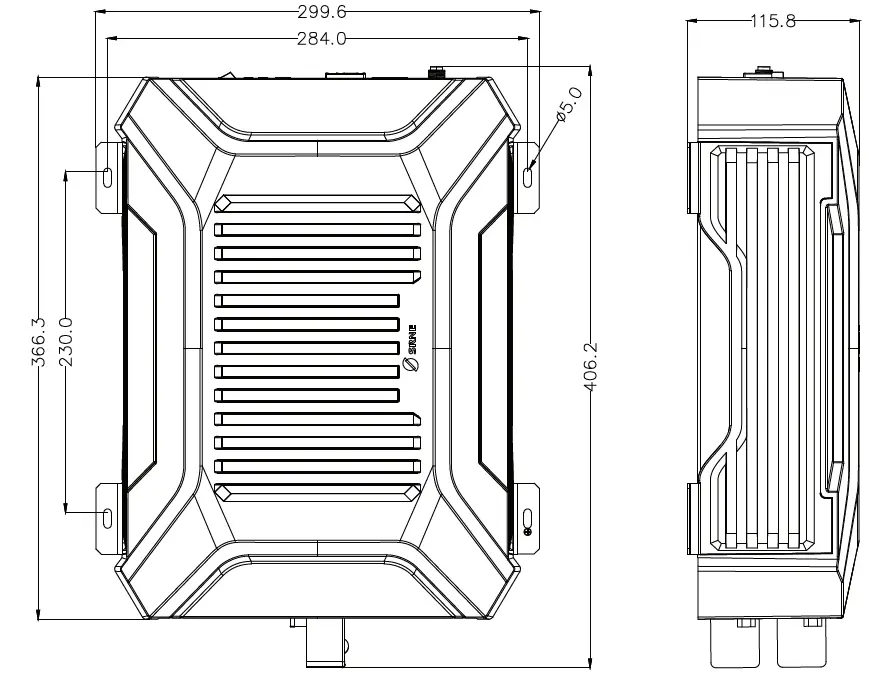
Specification
| Product model | IU12-2KW | IU24-3KW | Remarks |
| Rated output power W | 2000W | 3000W | |
| Rated output power VA | 2000VA | 3000VA | |
| Withstand instantaneous impact power | 4000W | 6000W | |
| Rated output voltage | 110VAC/120VAC(±3%) | Default: 120 V, adjusted by communication | |
| Output frequency | 50/60HZ(±0.2%) | Default: 60 HZ, adjusted by communication | |
| Output wave | Pure sine wave | ||
| Output harmonic component | THDV < 4% (pure resistance load) | ||
| Load power factor | 0.2-1 (load power ≤ output continuous power) | ||
| Rated input voltage | 12VDC | 24VDC | |
| Input voltage range | 10.8~16.0VDC | 21.6~32.0VDC | |
| Rated output efficiency | >89.0% | >90.0% | |
| Maximum output efficiency | > 92.0% (30% overload) | > 93.5% (30% overload) | |
| Standby current | <0.2A | <0.12A | OFF |
| No-load current | <1.0A | <0.95A | ON, No load |
| RS485 communication | Non-isolated RS485 communication, power supply 5VDC/200mA, remote switch of interface integration and CAN communication function (optional) | ||
| USB interface | Dual USB output, 5VDC/2A | ||
| ON/OFF/ECO mode | ON – AC normal output OFF – no AC output, standby ECO – energy-saving mode, auto switch | ||
| ECO starting power | <30W | 30-100W (adjustable) | |
| ECO interval time | 1min | 30s-30min (adjustable) | |
| TTL interface | Non-isolated TTL communication, power supply 12.5V/200mA | ||
| Indicator | Green – normal operation; Red – fault | ||
| External switch contact interface | Switch on or off by control equipment such as external relay and mechanical switch | Adjust the 3rd position rocker switch to ON when using this function | |
| Protection function | Input over-voltage/over-discharge protection, output overload/short-circuit protection, and device over- temperature protection | No input reverse connection protection! | |
| Operating ambient temperature | -20℃~60℃ | ||
| Storage ambient temperature | -35℃~80℃ | ||
| Relative humidity | ≤95% | ||
| Protection grade | IP20 | ||
| Heat-dissipating method | Natural heat dissipation + intelligent air cooling | ||
| Noise | ≤60dB | ||
| Product dimension | 406*300*115mm | ||
| Installation dimension | 230*284*φ5mm | ||
| Net weight | 5.3kg | ||
Description of interface function
RS485 communication
- Default baud rate: 9,600 bps, check bit: none, data bit: 8 bit, stop bit: 1 bit
- Interface type: RJ45, communication power supply output specification: 5VDC/200mA
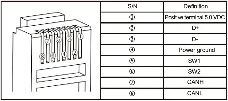
- The RS485 communication line sequence is defined as follows, with interface integrating remote switch interface (SW1/SW2) and CAN communication interface. When the switch interface (SW1/SW2) is floating and open circuit = OFF mode; when the switch interface (SW1/SW2) is short-circuited = ON mode.
USB interface
Dual USB output interface with a total output capacity of 5V 2A is capable of charging mobile phone/PAD and other mobile devices, and no output when the battery is over-discharged or with over-voltage.
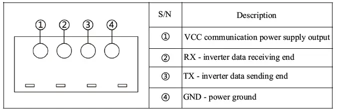
TTL communication interface
- Default baud rate: 9,600 kps; parity bit: none; data bit: 8 bit; stop bit: 1 bit
- Communication power output specification: 12.5 V/200 mA

Operating mode switch
With a 3rd position boat switch, the inverter has 3 operating modes including OFF, ON, and ECO when the external switch contact is closed.
| Switch position | Definition of mode | Description of mode |
| OFF | Idle mode, no AC output | Device is in standby idle state, indicator, communication function, USB output and other functions are normal, no AC output |
| ON | Normal mode with AC output | Device is in normal working state with AC output |
|
ECO | Energy-saving mode with Intermittent AC output | Device with the detected output load power lower than the ECO starting power (default 30W) will automatically close the AC output, enter idle mode, and re-start the AC output after ECO interval time (default 1min). And the AC will continuously output if the load power is larger than the ECO starting power (+10 W); |
| Remark: When using an APP or other communication devices to switch the working mode, the current actual working mode will be inconsistent with the boat switch position. The working mode of the inverter is based on the last adjusted position at the APP or communication device or the boat switch. | ||
LED indicator/buzzer
- Running indicator – green; fault indicator – red
- Indicator/buzzer are defined as follows:
Working state Running indicator (Run) – green Fault indicator (Fault) – red Buzzer Idle mode Single flash OFF No buzz Normal mode Normal ON OFF No buzz ECO mode Slow flash OFF No buzz Battery over-discharge OFF Slow flash 1 HZ buzz Battery over-voltage OFF Fast flash 1 HZ buzz Over-temperature protection of device OFF Double flash 1 HZ buzz Overload operation Normal ON Single flash 1 HZ buzz Overload protection OFF Single flash 1 HZ buzz Load short-circuit protection OFF Normal ON 1 HZ buzz Other faults (bus over-current/ inverter over-current/abnormal output voltage) OFF
Normal ON
1 HZ buzz
Fan fault – output Slow flash Slow flash No buzz Fan fault – no output OFF Single flash 1 HZ buzz Definition of indicator flashing: Slow flash 1s ON, 1s OFF in 2s Single flash 0.1s ON, 1.9s OFF in 2s Double flash 0.1s ON, 0.1s OFF, 0.1s ON and 1.7s OFF in period 2s Fast flash 1s ON, 0.1s OFF in 0.2s
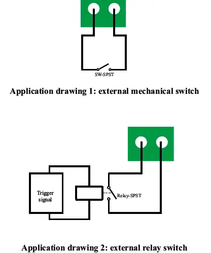
External switch contact interface
2P switch interface: Inverter can work when the interface is short-circuited; Inverter fails to work when the interface is open. The interface can be connected to a mechanical switch or relay to control the inverter to start/stop (this application requires keeping the mode switch in the ON or ECO mode position) in practical application.
Bluetooth communication
Built-in Bluetooth communication function can monitor the operation data, fault status and adjust the operation parameters of the inverter in real time through mobile APP.
CAN communication (optional)
Optional built-in CAN communication and RV-C protocol are available to monitor the inverter’s operation data and fault status, and adjust the inverter’s operation parameters in real-time via the PV. See 3.1 for pin definition of CAN communication interface.
Installation instructions
Installation precautions
Please read this manual carefully before installation to be familiar with the installation steps.
- Be careful when installing battery. Wear safety goggles when installing a lead-acid liquid battery. Once coming into contact with the battery acid, rinse with clean water timely.
- Keep away from metal objects to prevent short-circuit of battery.
- The battery may produce acid gas when charging. Make sure that the ambient environment is well-ventilated.
- When installing the cabinet, there must be enough space around the inverter for heat dissipation; Do not install the inverter and lead-acid battery in the same cabinet to avoid corrosion by acid gas generated during battery operation.
- As false connections and corroded cables may cause extreme heat to melt the cable insulation, burn surrounding materials and even cause a fire, it is necessary to ensure that the connections are tightened, and the cables are fixed with ties to avoid loose connections due to shaking of cable on the move. The system connection cables selected shall have a current density ≤5A/mm2.
- During outdoor installation, direct sunlight and rainwater infiltration shall be avoided.
- After the power switch is turned off, there is still high voltage inside the inverter. Do not turn on or touch the internal devices. Carry out relevant operations after the capacitor is discharged.
- Do not install the inverter in harsh environments such as moist, oily, flammable or explosive, or heavily dusty areas.
- Polarity at the battery input terminal of this product shall not be reversed. Otherwise, it may damage the device or cause unpredictable danger.
- The AC output is a high voltage, so please do not touch the wiring.
- Do not touch the working fan to prevent injury.
- It is necessary to confirm that the inverter is the only input device for load, and it is forbidden to use it in parallel with other input AC power to avoid damage.
Wiring specifications and circuit breaker selection
Wiring and installation must comply with national and local electrical codes.
- Battery input wiring specifications and circuit breaker selection
Model Rated input current Battery input wiring specifications Circuit breaker selection IU12-2KW 196A 40mm²/(3AWG*2) DC-2P-250A IU24-3KW 145A 30mm²/2AWG DC-2P-160A - AC output wiring specifications and circuit breaker selection
Model Rated output current AC output wiring specifications Circuit breaker selection IU12-2KW 18.2A 4mm²/11AWG AC-2P-32A IU24-3KW 27.3A 6mm²/10AWG AC-2P-50A - The above are reference specifications. Please select the appropriate specification and model according to actual situations.
- The wiring diameter is for reference only. If the distance between the inverter and the battery is relatively long, using a thicker wire can reduce the voltage drop to improve system performance.
- The above are only recommended wiring diameter and circuit breaker. Please select the appropriate wiring diameter and circuit breaker according to actual situations.
Installation and wiring
Installation steps:
Step 1: Please read the user manual carefully.
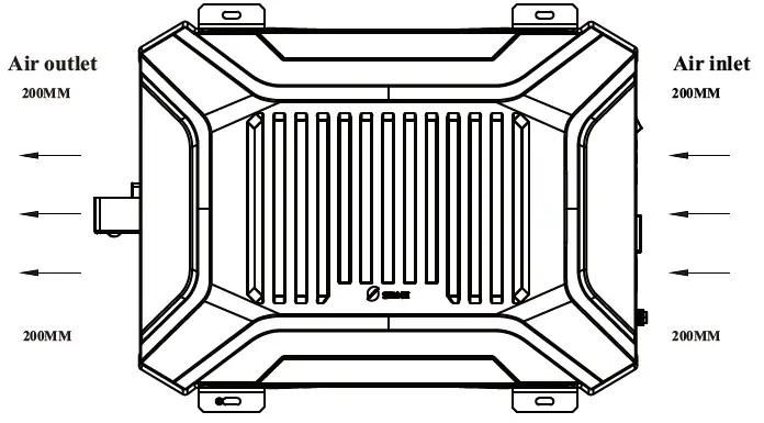
Step 2: Determine the installation position and the space for heat dissipation.
Determine the installation position (wall-mounted or horizontal installation method can be adopted): when installing the inverter, confirm that there is enough space of at least 200m reserved between the air outlet and air inlet of the inverter to facilitate air circulation.
If the device is installed n a closed box, ensure that heat dissipation is allowed through the container! Otherwise, dictate to use the device.
| The AC device shall be determined based on the inverter’s continuous output power. The impact power of the AC device cann!ot be higher than the inverter’s instantaneous impact power. Otherwise, the inverter may be damaged. | |
| Before wiring, switch the inverter to the OFF. Do not close the circuit breaker or fuse during wiring, and check if the electrode leads of each component are properly connected. The battery terminal shall be equipped with a fuse selected according to 2-2.5 times of the rated input current of the inverter, and the fuse must be at least 150 mm away from the battery terminal. There is no reverse connection protection for the input, check if the Positive and Negative are connected correctly before connecting. |
Wiring sequence:
Ground wire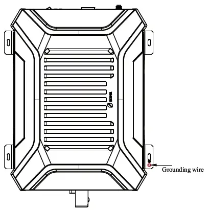
Positive/Negative wires of storage battery
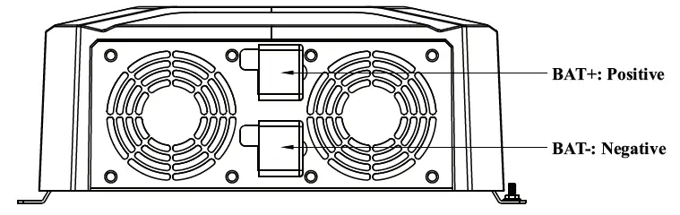
There is no reverse connection protection for the input, check if the Positive and Negative are connected correctly before connecting, or the inverter may be damaged!
AC device
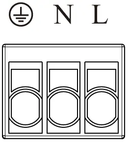
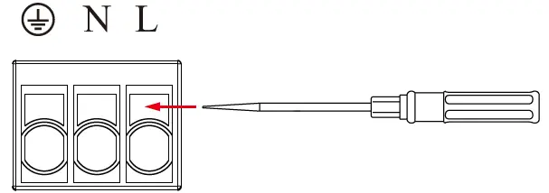
- The device has two AC output interfaces. Connect the load device to the following 3P terminals if the power of a single load device is higher than 70% of the rated power, defined as follows:

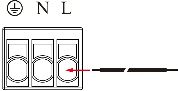
- Single strand copper wire with a wire diameter less than 4 mm² is recommended;
- Add soldering tin to the wiring place to make it integral and insert it into the corresponding hole if multiple strands of wire are used;
- Please connect the ground wire first, then the fire wire L and zero wire N.

- Stop the inverter to remove the wiring, then use a sharp tool to insert the small hole above the interface and pull out the connecting wire by force.

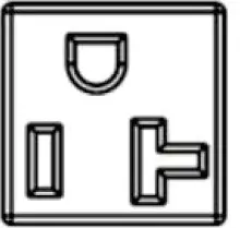
- The inverter is equipped with a standard American-Standard terminal, as shown in the drawing below, with a maximum current capacity of 20A.

Step 4: Start the inverter
- Close the circuit breaker at the inverter’s DC input terminal or the fuse at the battery;
- Short circuit the inverter’s external switch contact interface (short-circuited for factory);
- Set the inverter’s mode switch to ON to start the inverter output: The running indicator is always green, and AC power output is normal;
- Close the circuit breakers on the AC load line, turn on the AC load one by one, and check the operating status of the inverter and the load;
- If the fault indicator is red with a buzzer alarm after starting the inverter, please turn off the load and inverter and refer to Common Problems and Solutions for troubleshooting. Repeat the preceding steps after the fault is rectified.
Protection function
Input of over-voltage protection
When the battery voltage is higher than the input voltage of over-voltage protection, turn off the AC output, and the fault indicator lamp and buzzer will prompt; When the battery voltage is lower than the input voltage (1V) of over-voltage protection, the AC output is recovered.
| 12V system | 24V system | |
| Input voltage of over-voltage protection | 16.0V | 32.0V |
| Input recovery voltage of over-voltage protection | 15.0V | 31.0V |
| Although the inverter has an input of overvoltage protection, the input voltage of the 12 V system shall not be ! higher than 20 V; The 24 V system inpu!t voltage shall not be higher than 35 V, otherwise, the inverter may be damaged. | ||
Input of low-voltage protection
When the battery voltage is lower than the input voltage of low-voltage protection, turn off the AC output, and the fault indicator lamp and buzzer will prompt; When the battery voltage is higher than the input recovery voltage of low-voltage protection, the AC output is recovered.
| 12V system | 24V system | |
| oltage of over-voltage protection | 10.8V | 21.6V |
| Input recovery voltage of low-voltage protection | 12.0V | 24.0V |
Output of overload protection
Make corresponding protection according to different overload levels when the AC load is greater than the rated output power, as follows:
| Load power | Possible duration |
| 102%≤Po≤120% | 1min |
| 120%<Po≤150% | 30s |
| Po﹥150% | 10s |
The AC output has three automatic recoveries for inverter’s overload protection (the first time delay is 5S, the second time delay is 10s, and the third time delay is 15s). The AC output will not automatically recover at the fourth time until restarting the inverter after checking the device and removing the faults.
Output of short-circuit protection
When the AC output L/N is short-circuited, the inverter automatically turns off the AC output, and fault indicator and buzzer prompt. The AC output has three automatic recoveries for inverter’s short-circuit protection (the first time delay ! is 5S, the second time delay is 10s, and the third time delay is 15s). The AC output will not automatically recover at the fourth time until restarting the inverter after removing the faults.
Over-temperature protection of device
With multiple internal temperature detections, the device under any temperature higher than the device over-temperature protection will automatically turn off the AC output, and fault indicator and buzzer will prompt; The AC output will be recovered if the temperature is lower than the over-temperature protection. Please keep a good ventilation environment to ensure that the inverter can operate reliably and stably at full power for a long time.
Fault protection of fan
If the fan is blocked or not operate for other reasons, the AC output of the inverter can only work within 30% of the rated output power and will be turned off when the load power is higher than 30% of the rated power. To ensure that the inverter can run reliably and stably at full power for a long time, please keep a good installation environment to avoid fan blocking by oil and wire. And check the fan operation regularly.
Common problems and solutions
| S/N | Phenomenon | Cause | Possible cause | Solutions |
| 1 | Red light flashing slowly, green light off, buzzer buzzing, no AC output | Over-low battery input voltage | 1. Excessive voltage drop due to over-small battery wiring diameter 2. Low battery power. | 1. Choose the suitable wires; 2. Timely charge the battery until the low voltage recovery voltage can self-restore the output. |
| 2 | Red light flashing quickly, green light off, buzzer buzzing, no AC output | Over-high battery input voltage | 1. Mismatch between battery voltage and device system voltage | Measure the positive and negative terminal voltage of the device with a voltmeter to determine whether they are higher than the over- voltage protection voltage, and recover by adjusting the input voltage |
| 3 | Red light single flashing, green light always on, buzzer buzzing, with AC output | Overload | Power of load device higher than rated output power | Check whether the AC load is within the rated power range of the inverter; |
| 4 | Red light single flashing, green light off, buzzer buzzing, no AC output | Overload | Power of load device higher than rated output power | Check whether the AC load is within the rated power range of the inverter; Eliminate the load overload fault and restart the inverter to restore normal operation. |
| 5 | Red light always on, green light off, buzzer buzzing, no AC output | Load short-circuited | 1. AC output of the inverter short-circuited 2. AC device L/N short-circuited | Check whether the AC load wiring is short- circuited; Eliminate the load short-circuit fault and restart the inverter to restore normal operation. |
| 6 | Red light double flashing, green light off, buzzer buzzing, no AC output | Over-high device temperature | Internal temperature of device higher than the set over- temperature protection | Improve the quality of ventilation, clear the vent, reduce the temperature around the inverter, and restart the device after the temperature is reduced. Please derate the amount if troubleshooting fails. |
| 7 | Red light and green light single flashing, buzzer buzzing, with AC output or unable to reach the rated power output | Fan fault | Fan blocked by any object | Check whether the fan works properly. |
System maintenance
In order to maintain the best long-term performance, it is recommended to conduct following checks twice a year.
- Make sure that the airflow around the inverter is smooth and remove any dirt or debris from the heat sink. Check whether all exposed wires are damaged by exposure to sunlight, friction with other objects around them, dryness, bite by insects or rodents, etc. The wires shall be repaired or replaced if necessary.
- Verify for the consistency of indicator and display with the operation of the device. Please pay attention to any faults or errors, and take corrective actions if necessary.
- Check all wiring terminals for corrosion, insulation damage, signs of high temperature or burning/discoloration, and tighten the screws.
- Check for dirt, nesting insects and corrosion, and clean up as required.
- The arrester failed shall be replaced in time against lightning damage to the inverter or even other device of the user.
- Danger of electric shock! Make sure that the inverter power is disconnected and the power in the capacitor is discharged before carrying out the corresponding checks or operations!
The Company does not assume any liability for damage caused by:
- Improper use or use in improper site.
- Current, voltage and power of the load exceeding the limit of the inverter.
- Temperature in the operating environment exceeding the limited operating temperature range. Arcing, fire and explosion caused by failure to follow inverter markings or manual instructions. Disassemble and repair the inverter without permission.
- Force majeure.
- Damage that occurs in transportation or handling of the inverter.


