TRUPER ROEL-20N Plus Rotary Hammer
![]()
![]() Read this manual thoroughly before using the tool.
Read this manual thoroughly before using the tool.
![]() To gain the best performance of the tool, prolong the duty life, make the Warranty valid if necessary, and to avoid hazards of fatal injuries please read and understand this Manual before using the tool.
To gain the best performance of the tool, prolong the duty life, make the Warranty valid if necessary, and to avoid hazards of fatal injuries please read and understand this Manual before using the tool.
Keep this manual for future references.
The illustrations in this manual are for reference only. They might be different from the real tool.
Use and care recommendations

 DO NOT CHANGE THE SELECTOR WHILE THE MACHINE IS WORKING.
 CLEAN AFTER EACH USE TO REMOVE EXCESS OF DUST.
 FULFILL THE WORKING CYCLES.
50 min of work and 20 min of rest. Daily maximum 6 hours.
Perform periodic MAINTENANCE to your machine (page 10).
Technical data
ROEL-20N
| Code | 16762 | |
| Description | Rotary Hammer | |
| Chuck | SDS Plus | |
| Voltage | 127 V | |
| Frequency | 60 Hz | |
| Current | 5.4 A | |
| Power | 0.8 Hp | |
| Impact energy | 2 Joules | |
| Boring capacity | Concrete: 11/16” Steel: 1/2” Wood: 1-1/4” | |
| Speed | Drill: 0 – 2 200 RPM | |
| Impacts | 0 impact/min – 5 510 impact/mi | |
| Work Cycle | 50 minutes’ work per 20 minutes idle. Maximum 6 hours per day | |
| Conductors | 18 AWG x 2C with insulation temperature of 221 °F | |
| Insulation | Class II | IP Grade IP20 |
![]() Avoid the risk of electric shock or severe injury. When the power cable gets damaged it should only be replaced by the manufacturer or at a
Avoid the risk of electric shock or severe injury. When the power cable gets damaged it should only be replaced by the manufacturer or at a ![]() Authorized Service Center.
Authorized Service Center.
The build quality of the electric insulation is altered if spills or liquid gets into the tool while in use.
Do not expose to rain, liquids and/or dampness.![]() Before gaining access to the terminals all power sources should be disconnected.
Before gaining access to the terminals all power sources should be disconnected.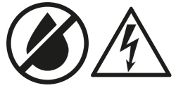
Power Requirements
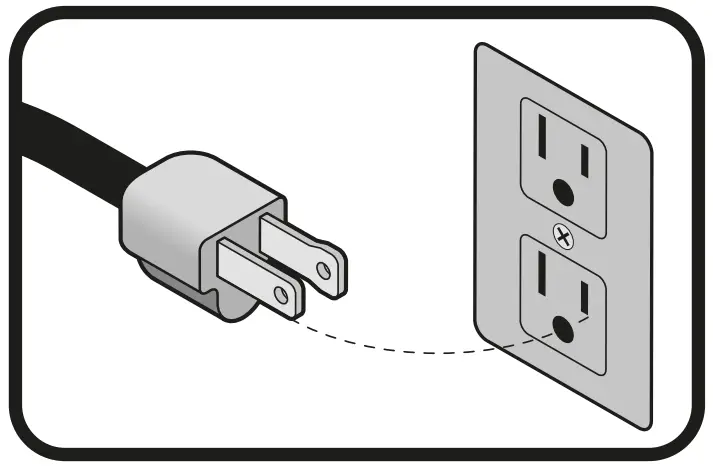
![]() Tools with double insulation and reinforced insulation are equipped with a polarized plug (one prong is wider than the other). This plug will only fit in the right way into a polarized outlet. If the plug cannot be introduced into the outlet, reverse the plug. If it still doesn’t fit, call a qualified electrician to install for you a polarized outlet. Do not alter the plug in any way. Both insulation types eliminate the need of both a grounded third power cord with three prongs or a grounded power connection
Tools with double insulation and reinforced insulation are equipped with a polarized plug (one prong is wider than the other). This plug will only fit in the right way into a polarized outlet. If the plug cannot be introduced into the outlet, reverse the plug. If it still doesn’t fit, call a qualified electrician to install for you a polarized outlet. Do not alter the plug in any way. Both insulation types eliminate the need of both a grounded third power cord with three prongs or a grounded power connection![]() .
.
![]() When using an extension cable, verify the gauge is enough for the power that your product needs. A lower gauge cable will cause voltage drop in the line, resulting in power loss and over heating. The following table shows the right size to use depending on cable’s length and the ampere capability shown in the tool’s nameplate. When in doubt use the next higher gauge.
When using an extension cable, verify the gauge is enough for the power that your product needs. A lower gauge cable will cause voltage drop in the line, resulting in power loss and over heating. The following table shows the right size to use depending on cable’s length and the ampere capability shown in the tool’s nameplate. When in doubt use the next higher gauge.
Ampere Capacity | Number of Conductors | Extension gauge | |
| from 6’ to 49’ | higher than 49’ | ||
| from 0 A and up to 10 A | 3 (one grounded) | 18 AWG(* | 16AWG |
| from 10 A and up to 13 A | 16 AWG | 14 AWG | |
| from 13 A and up to 15 A | 14 AWG | 12AWG | |
| from 15 A and up to 20 A | 8 AWG | 6 AWG | |
* It is safe to use only if the extensions have a built-in artifact for over current protection.
AWG = American Wire Gauge. Reference: NMX-J-195-ANCE
![]() When operating power tools outdoors, use a
When operating power tools outdoors, use a![]() grounded extension cable labeled “For Outdoors Use”. These extensions are especially designed for operating outdoors and reduce the risk of electric shock
grounded extension cable labeled “For Outdoors Use”. These extensions are especially designed for operating outdoors and reduce the risk of electric shock![]() .
.
 | General power tool safety warnings |  |
![]() WARNING! Read carefully all safety warnings and instructions listed below. Failure to comply with any of these warnings may result in electric shock, fire and / or severe damage. Save all warnings and instructions for future references.
WARNING! Read carefully all safety warnings and instructions listed below. Failure to comply with any of these warnings may result in electric shock, fire and / or severe damage. Save all warnings and instructions for future references.
Work area
 Keep your work area clean, and well lit.
Cluttered and dark areas may cause accidents. Never use the tool in explosive atmospheres, such as in the presence of flammable liquids, gases or dust.
Sparks generated by power tools may ignite the flammable material. Keep children and bystanders at a safe distance while operating the tool.
Distractions may cause loosing control.
Electrical Safety
![]() The tool plug must match the power outlet. Never modify the plug in any way. Do not use any adapter plugs with grounded power tools.
The tool plug must match the power outlet. Never modify the plug in any way. Do not use any adapter plugs with grounded power tools.
Modified plugs and different power outlets increase the risk of electric shock.
Avoid body contact with grounded surfaces, such as pipes, radiators, electric ranges and refrigerators.
The risk of electric shock increases if your body is grounded.
Do not expose the tool to rain or wet conditions.
Water entering into the tool increases the risk of electric shock.
Do not force the cord. Never use the cord to carry, lift or unplug the tool. Keep the cord away from heat, oil, sharp edges or moving parts.
Damaged or entangled cords increase the risk of electric shock.
When operating a tool outdoors, use an extension cord suitable for outdoor use.
Using an adequate outdoor extension cord reduces the risk of electric shock.
If operating the tool in a damp location cannot be avoided, use a ground fault circuit interrupter (GFCI) protected supply.
Using a GFCI reduces the risk of electric shock.
Personal safety
Stay alert, watch what you are doing and use common sense when operating a tool. Do not use a power tool while you are tired or under the influence of drugs, alcohol or medication.
A moment of distraction while operating the tool may result in personal injury.
Use personal protective equipment. Always wear eye protection.
Protective equipment such as safety glasses, anti-dust mask, non-skid shoes, hard hats and hearing protection used in the right conditions significantly reduce personal injury.![]()
Prevent unintentional starting up. Ensure the switch is in the “OFF” position before connecting into the power source and / or battery as well as when carrying the tool.
Transporting power tools with the finger on the switch or connecting power tools with the switch in the “ON” position may cause accidents.
Remove any wrench or vice before turning the power tool on.
Wrenches or vices left attached to rotating parts of the tool may result in personal injury.
Do not overreach. Keep proper footing and balance at all times.
This enables a better control on the tool during unexpected situations.![]() Dress properly. Do not wear loose clothing or jewelry. Keep hair, clothes and gloves away from the moving parts.
Dress properly. Do not wear loose clothing or jewelry. Keep hair, clothes and gloves away from the moving parts.
Loose clothes or long hair may get caught in moving parts.
If you have dust extraction and recollection devices connected onto the tool, inspect their connections and use them correctly.
Using these devices reduce dust-related risks.
Power Tools Use and Care
![]() Do not force the tool. Use the adequate tool for your application.
Do not force the tool. Use the adequate tool for your application.
The correct tool delivers a better and safer job at the rate for which it was designed.
Do not use the tool if the switch is not working properly.
Any power tool that cannot be turned ON or OFF is dangerous and should be repaired before operating.
Disconnect the tool from the power source and / or battery before making any adjustments, changing accessories or storing.
These measures reduce the risk of accidentally starting the tool.![]() Store tools out of the reach of children. Do not allow persons that are not familiar with the tool or its instructions to operate the tool.
Store tools out of the reach of children. Do not allow persons that are not familiar with the tool or its instructions to operate the tool.
Power tools are dangerous in the hands of untrained users.![]() Service the tool. Check the mobile parts are not misaligned or stuck. There should not be broken parts or other conditions that may affect its operation. Repair any damage before using the tool.
Service the tool. Check the mobile parts are not misaligned or stuck. There should not be broken parts or other conditions that may affect its operation. Repair any damage before using the tool.
Most accidents are caused due to poor maintenance to the tools.
Keep the cutting accessories sharp and clean.
Cutting accessories in good working conditions are less likely to bind and are easier to control.
Use the tool, components and accessories in accordance with these instructions and the projected way to use it for the type of tool when in adequate working conditions.
Using the tool for applications different from those it was designed for, could result in a hazardous situation.
Service
Repair the tool in a ![]() Authorized Service Center using only identical spare parts.
Authorized Service Center using only identical spare parts.
This will ensure that the safety of the power tool is maintained.
 This tool is in compliance with the Official Mexican Standard (NOM – Norma Official Mexicana).
Safety warnings for drills and hammer drills
Choose the right bit
 Choose the right bit for the work piece. It reduces the risk of severe injury and makes the job easier.
- To drill concrete or stone, use bits specifically designed for concrete.
- For metal, wood, or plastic use the 3-jaw chuck with SDS adapter (included); the measurements cover a minimum of 1.5 mm up to the maximum capacity of the broquero (13 mm)
- Do not try using bits exceeding the chuck capacity.
Before using the hammer drill
- Before starting work with the drill, take a few minutes to assess the job to be done and double-check all the safety caution rules.
 Fit the bit into the chuck. Remove the chuck key before drilling. Failure to follow this instruction makes the key to shoot out with great speed and cause severe injury.
 Before drilling walls, floors or ceiling, look for any built-in objects, like power cables and conductors or pipes.
- Verify the switch is in the OFF position before connecting the drill. Otherwise, it can unexpectedly start operating and could cause severe injuries.
- Turn off and disconnect the tool before reversing the chuck’s direction as well as fitting or replacing bits.
While operating the hammer drill
- Use the auxiliary handles, if supplied with the tool. Loss of control may result in personal injury.
- Hold the tool by the isolated parts. The cutting part of bit could come into contact with hidden wiring or with its own power cord. Making contact with a power cord causes the tool metal parts get electrified and may result in electric shock to the user. • Do not force the tool to excessive workloads.
- Turn off the hammer drill immediately if the bit gets stuck into de work piece. Then, remove the bit off the work piece. Do not try removing stuck bits turning on and off the tool.
- Do not apply too much force on the tool in order to accelerate the drilling procedure. The bit could get damaged and the tool would loose efficiency and useful life.
- A large diameter bit causes a higher reactive force leading to losing control over the tool. To avoid this possibility, firmly hold the tool with both hands and keep balanced footing. Drill at 90°
- Be prepared to relax the drilling force when the bit goes through the material. Sudden movements could break the bit or damage the hammer drill.
- Do not touch the bit or the orifices immediately after drilling. Wait until they cool down to handle them. Do not try to cool them down using water or oil.
- Immediately after using do not set the tool where there are particles and / or dust. They can be absorbed into the tool mechanism and cause damage.
 Use earplugs when using the hammer drill. Exposure to noise can cause hearing loss.
 Use dust mask and dust extractor if necessary. Remember that materials such as asbestos, paint with lead, additives, some types of wood, metals or minerals are highly toxic.
 Use safety glasses.
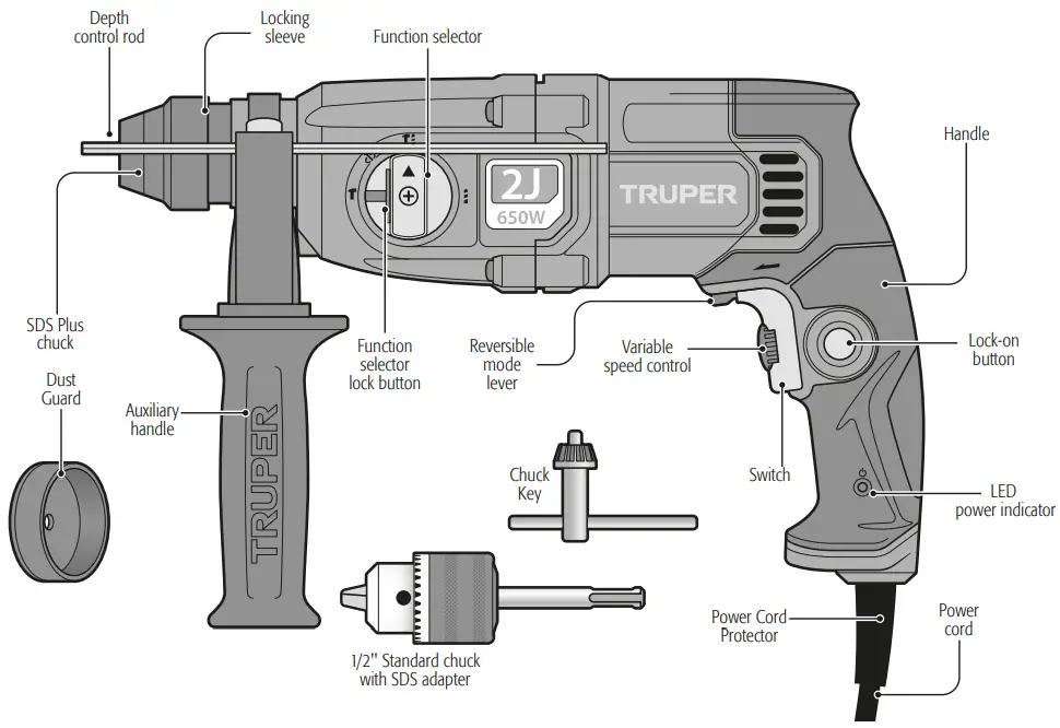
Parts
Preparation
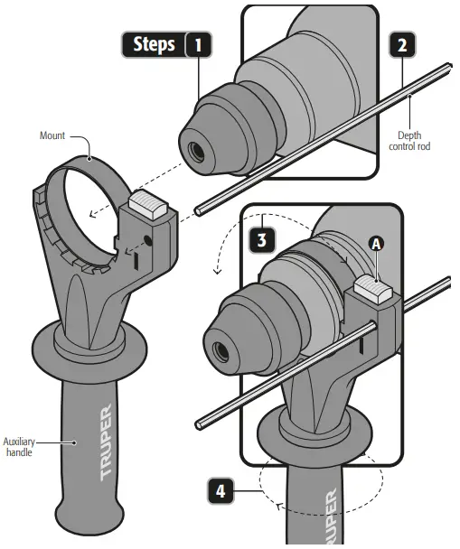
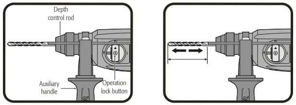
Auxiliary Handle and Depth Control Rod Assembly
- Turn the auxiliary handle in a clockwise direction while is released so that the mount opening can pass freely on top of the chuck.
- Insert the hammer drill through the auxiliary handle mount.
- Press the lock (A) to insert the depth control rod in the hexagonal mount orifice.
- Rotate the auxiliary handle together with the mount until set into the adequate position to operate the tool.
- Turn the auxiliary handle to fix the mount firmly to the hammer drill head.
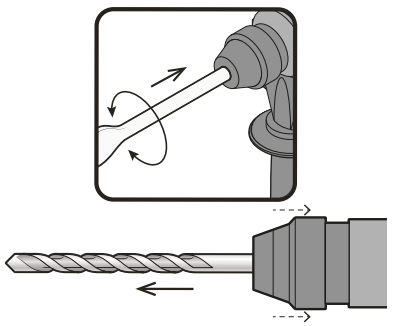
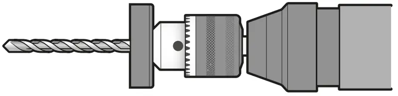
Bit and Accessory Installation or Removal
- Clean and lubricate lightly the bit and / or accessory before installing.
- Insert the shaft of the bit into the SDS socket.
- Twist and push the bit in until it engages.
- After installing it, always make sure that the bit is firmly in place by trying to pull it back out.
- To remove the bit, pull down on the bit sleeve and push the bit out. Do not try to install or remove bits and / or accessories unless the tool is disconnected.
Depth control rod adjustment
- Push and hold the depth bar release button on the auxiliary handle.
- Move the depth rod so that the distance between the end of the bar and the end of the drill bit is equal to the desired drill depth.
- Release the button to lock the position bar.
- When drilling with the depth bar, stop when the end of the bar reaches the surface of the material.
Start Up
Start up and operation control
- Intermittent Operation:
Connect the plug to the power supply.
Press the switch (A) to start the hammer drill start working.
To stop using, just release the switch. - Continuous Operation:
Connect the plug to the power supply.
Press the switch (A) and block it by pressing the lock-on button (B).
To interrupt the function press and then release the switch.
Speed Control
- The tool can be operated in different speeds. Select the speed adjusting the speed control (+ and -) (C) in the switch.
- Turn the speed control in a clockwise direction to increase the hammer drill speed and torsion.
- Turn in the opposite direction to diminish speed and torsion.
- Speed increases depending or the pressure exercised into the switch (A).
| Speed | Operation mode | Material or Use |
| High | Rotary Hammer / Chiseling | Concrete and Stone |
| Medium | Drill | Metal |
| Low | Rotary Hammer / Drill | Start holes |
Rotation Direction
To make the bit turn forward and start drilling move the selector to the rotation direction (D) up to the arrow pointing the chuck. To make it turn in reverse and use the drill as screwdriver move the rotation direction lever towards the arrow pointing the hammer drill handle.![]() Never use the tool in reverse with the operation mode selector in the IMPACT positions (
Never use the tool in reverse with the operation mode selector in the IMPACT positions (![]() ). Otherwise the impact system will get seriously damaged.
). Otherwise the impact system will get seriously damaged.![]() Never change the position in the rotation selector lever while the hammer drill motor is running.
Never change the position in the rotation selector lever while the hammer drill motor is running.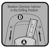
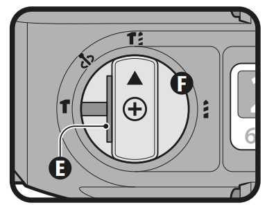
Changing the Operation Mode
- Press the blocking button (E) and turn the function selector (F) into one of the 4 positions depending on the work to carry out until hearing a click. Assure the selector is properly secured. Never change the function selector position when the hammer drill motor is running.
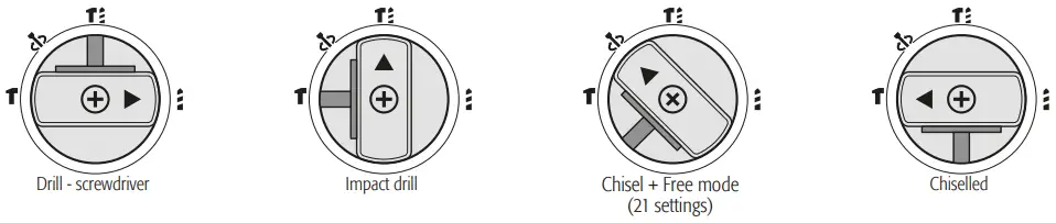
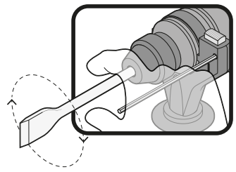
Modifying the position of the chisel angle
The chisel can be blocked in 21 angles. This allows to adopt an optimal working position in each case.
- Mount the chisel on the SDS chuck.
- Turn the operation mode selector to the fchisel + adjustable angle positio
 .
. - Turn the SDS chuck until you get the desired position.
- Turn the operation mode selector to the chiseling position. The chuck is blocked.
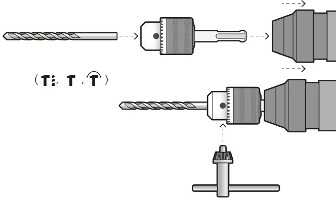
Wood, Metal or Plastic Drilling
Metal, wood or plastic can be drilled with the tool using drill / accessory bit) three jaws chuck with an SDS adapter.
- To install the three jaws chuck, go as with any other SDS accessory (page 7, Installing or removing the bit/accessory).
- Set the bit into the three jaws chuck until is stops and secure with the chuck key tightening each one of the orifices alternatively.
Never use the three jaws chuck with the selector in the operation mode in the IMPACT positions ( ).
).
Operation
Percussion drill.
- Set the knob that changes the drive mode to the symbol
 .
. - Position the bit at the desired location in the hole, then actuate the switch.
- Do not force the tool. With less pressure, you get better results. Keep the tool in the proper position and prevent it from slipping out of the hole.
- Do not apply more pressure when the hole is clogged with particles or chips. Instead, actuate the tool with no load, and then withdraw the bit partially from the hole. If you repeat this action several times, the hole will be cleaned and normal preforming will resume.
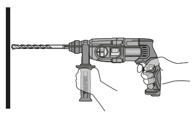
 When drilling a hole, when the hole becomes clogged with chips and particles, or when it hits the reinforcing rods of reinforced concrete, a sudden and tremendous torque is exerted on the tool/drill. Always use the side handle (auxiliary) and hold the tool firmly by the side handle and the switch handle during operations. Failure to do so may result in loss of control of the tool and possibly serious injury.
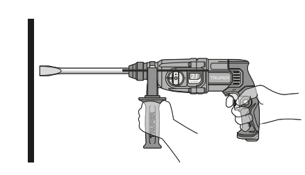
Chiselling / Carving / Demolition
- Set the knob that changes the drive mode to the symbol
 .
. - Hold the tool firmly with both hands.
- Turn the tool on and apply light pressure to the tool to prevent the tool from bouncing uncontrollably. Excessive pressure with the tool will not improve efficiency.
Installation and use of dust cover
- Slide the dust cover over the bit before drilling any holes vertically above your head.
- The dust cover will prevent dust from falling on the tool and on yourself when drilling.
- The size of the bits to which the dust cover can be fixed is from 8 mm to 10 mm.
Overload Brake
The tool is built with an overload breaker that stops the axis force (causing a rattling sound) if the accessory gets stuck. If this happens:
- Turn off the tool immediately.
- Remove the stuck accessory.
- Turn On the tool.
Additional Information
- SDS accessories need freedom of movement inside the chuck. This causes eccentricity when the tool is unloaded. However, the accessory gets centered automatically during the operation with no affectation the drilling precision.
- When the tool is new it requires 5 hours working to gain its maximum efficiency.
- When using the tool in the drill or hammer drill mode first, set the bit tip in the point where the orifice will be bored and then press the switch.
Cleaning and Care
- To guarantee adequate motor cooling, always keep slots clean and free of obstructions.
- Regularly inspect all the assembly screws. Double-check they are properly tighten. If any screw is loose screw it immediately.
Service
- Service should only be made in a Authorized Service Center. Service and maintenance performed by non-qualified people may be dangerous and can lead to personal injuries. It also makes the product Warranty void.
Lubrication
- We recommend lubricating the tool transmission every carbon brush change in a
 Authorized Service Center.
However; In two to six months, depending on usage, take or send your tool to an Authorized Service Center for complete cleaning, inspection and lubrication. Tools that are used constantly in production work will need to be re-lubricated more frequently, and tools that have been “out of service” for long periods of time should be re-lubricated before being used again.
Carbon Brush Replacement
- The carbon brush wear indicator LED will be lit when the carbon brushes are worn out in excess or show excessive sparking go to a Authorized Service Center .
- Carbon brushes shall be checked periodically and replaced always in a Authorized Service Center.
- When replaced, ask the technician to inspect if the new carbon brushes move freely in the carbon brush housing. Ask to turn on the tool during five minutes to make the contact in the carbon brushes and the commuter even.
- Use only original spare carbon brushes, designed specifically with the right strength and electric resistance for each type of motor. Carbon brushes with different specifications may damage the motor.
- When replacing carbon brushes, always change both.
In the event of any problem contacting a Truper Authorized Service Center, please see our webpage www.truper.com to get an updated list, or call our toll-free numbers 800 690-6990 or 800 018-7873 to get information about the nearest Service Center.
AGUASCALIENTES
DE TODO PARA LA CONSTRUCCIÓN
GRAL. BARRAGÁN #1201, COL. GREMIAL, C.P. 20030,
AGUASCALIENTES, AGS. TEL.: 449 994 0537
BAJA CALIFORNIA
SUCURSAL TIJUANA
AV. LA ENCANTADA, LOTE #5, PARQUE INDUSTRIAL EL
FLORIDO II, C.P 22244, TIJUANA, B.C.
TEL.: 664 969 5100
BAJA CALIFORNIA SUR
FIX FERRETERÍAS
FELIPE ÁNGELES ESQ. RUIZ CORTÍNEZ S/N, COL. PUEBLO
NUEVO, C.P. 23670, CD. CONSTITUCIÓN, B.C.S.
TEL.: 613 132 1115
Code | Model | Brand |
16762 | ROEL-20N |
Warranty
Duration: 5 year. Coverage: parts, components and workmanship against manufacturing or \operating defects, except if used under conditions other than normal; when it was not operated in accordance with the instructive; was altered or repaired by personnel not authorized by Truper®. To make the warranty valid, only present the product in the establishment where you bought it or in Corregidora 35, Centro, Cuauhtémoc, CDMX, 06060, where you can also purchase parts, components, consumables and accessories. The costs of transportation of the product that derive from its fulfillment of its service network are included. Truper will not require any proof of purchase to make the warranty effective. Phone number 800-018-7873. Made in China. Imported by Truper, S.A. de C.V. Parque Industrial 1, Parque Industrial Jilotepec, Jilotepec, Edo. de Méx. C.P. 54257, Phone number 761 782 9100.|
CUSTOMER SUPPORT