
STEVENS Digital Pressure and Temperature Sensor
Digital Pressure and Temperature Sensor
Product Information
The Digital Pressure and Temperature Sensor is a product of STEVENS WATER MONITORING SYSTEMS, INC. It is available in vented and non-vented models with order numbers ranging from 51168-201 to 51168-307. The sensor has a recommended yearly calibration order number of 32142. It can measure water depth up to 200 meters and has an overpressure limit of 400 meters. The sensor has surge protection components for lightning protection, but damage due to lightning is not covered under warranty. The Smart PT is warranted to withstand freezing conditions without damage if the black cap is removed, except for the 0.2 bar vented sensor. The Smart PT has a vent tube running the length of the cable to reference water pressure against barometric pressure. It comes with an engineered resin cap to protect the ceramic membrane from ice expansion damage.
Product Usage Instructions
- Choose the appropriate model based on the required measurement range and order number.
- Before installation, connect the desiccant capsule and remove the yellow cap from the vent tube of the vented version.
- If the sensor is expected to freeze, remove the engineered resin cap to avoid damage due to ice expansion.
- Connect the wires following the color code provided in the manual. Only one communication interface should be connected: SDI-12 or Modbus.
- The Smart PT should be calibrated every year to correct for long-term drift. Before returning the sensor for calibration or repair, navigate to the `Support’ page at http://www.stevenswater.com and fill out the RMA form. If the sensor was used in contaminated water, it must be cleaned before shipping.
- Use SDI-12 Transparent Mode to issue commands. The first character of any command or response on SDI-12 is the sensor address, with a lowercase `a’ used to represent the address. Each SDI-12 sensor must have its own unique address. The default address is 0.
- The basic SDI-12 commands and responses are provided in the manual for reference.
Introduction
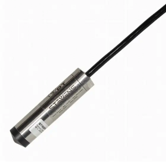
Stevens Smart PT is an advanced digital pressure and temperature sensor ideal for water level measurements as well as many other pressure and fluid level monitoring applications. The SDI-12 communications interface provides universal compatibility with industry-standard data loggers. In addition, Modbus RTU (over RS485) support expands communications to other types of data loggers and programmable logic controllers (PLCs). In addition to simple instantaneous pressure, level, and temperature measurements, Smart PT includes the ability to automatically record peak crest levels, and calculate average levels as well as a standard deviation all without complex datalogger configurations. Other advanced features include adjustable fluid density, automatic water temperature density compensation, and adjustable local gravity compensation. An M14-1 threaded sensor head allows for easy mounting to pipes. An included threaded cap offers a loophole that can be used to mount weights or pull the sensor through pipes or other small areas. The Smart PT is built to last for years in the field with fully sealed and potted components, a robust ceramic membrane, stainless-steel housing, and an industrial-quality cable.
| Order Number | Range (bar) | Water Depth (m) | Water Depth (ft) | Overpressure (m) |
| Vented | ||||
| 51168-201 | 0.2 | 2 | 6.6 | 50 |
| 51168-202 | 0.4 | 4 | 13 | 60 |
| 51168-203 | 1 | 10 | 33 | 100 |
| 51168-204 | 2 | 20 | 66 | 150 |
| 51168-205 | 4 | 40 | 130 | 250 |
| 51168-206 | 10 | 100 | 330 | 400 |
| 51168-207 | 20 | 200 | 660 | 400 |
| Non-Vented | ||||
| 51168-303 | 1.4 | 4 | 13 | 90 |
| 51168-304 | 2 | 10 | 33 | 140 |
| 51168-305 | 4 | 30 | 100 | 240 |
| 51168-306 | 10 | 90 | 300 | 390 |
| 51168-307 | 20 | 190 | 630 | 390 |
| Recommended Yearly Calibration | ||||
| 32142 | ||||
| Parameter | Accuracy | Unit |
| Pressure accuracy | 0.1% | Full scale |
| Long term stability | Max 0.15% per year | Full scale |
| Temperature accuracy | ±0.25 | °C |
| SDI-12 average current consumption | 1.5 | mA |
| Modbus average current consumption | 1.5 | mA |
| Parameter | Min | Max | Unit |
| Supply voltage during operation | 6 | 18 | V |
| Temperature during operation | -20 | 80 | °C |
Warranty
The Smart PT has internal surge protection components for lightning protection. However, damage due to lightning is not covered under the warranty. Except for the 0.2 bar vented sensor, the Smart PT is warranted to withstand freezing conditions without damage if the black cap is removed. The 0.2 bar vented sensor is more sensitive to overpressure and isn’t warranted for freezing conditions.
Wiring
Note: Only one communication interface should be connected: SDI-12 or Modbus.
| Wire Color | Signal |
| Black | Ground |
| Red | +12Vdc |
| Blue | SDI-12 Data |
| White | Modbus A |
| Green | Modbus B |
Vent Tube
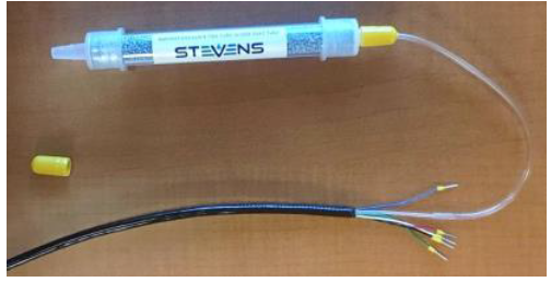
The vented version of the Smart PT has a tube running the length of the cable. This allows the water pressure on the front of the transducer to reference against barometric pressure. The Smart PT ships with a black cap over the end of the vent tube to prevent moisture ingress, and with a separate desiccant capsule. Before installation the desiccant capsule needs to be connected and the yellow cap removed.
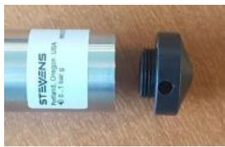
Ice
The Smart PT ships with an engineered resin cap designed to protect the ceramic membrane. It’s important to remove the cap if the Smart PT is expected to freeze. If the cap isn’t removed, expanding ice trapped under the cap will damage the ceramic membrane.
Packaging for calibration and repair
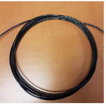
To correct for long-term drift, the Smart PT should be calibrated every year. Before returning the sensor for calibration or repair, navigate to the ‘Support’ page at http://www.stevenswater.com and fill out the RMA form. If the sensor was used in contaminated water, the sensor must be cleaned before shipping. Coil and zip-tie the sensor cable before shipping.
SDI-12 Commands and Responses
Command quick reference
- M: pressure, temperature
- M1: minimum, maximum
- M2: average, standard deviation
Addressing
The first character of any command or response on SDI-12 is the sensor address. A lowercase ‘a’ is used to represent the address. Each SDI-12 sensor must have its own unique address. The default address is “0”. Use SDI-12 “Transparent Mode” to issue commands.
Basic SDI-12 Commands
| Command | Response | Description |
| a! | a | Acknowledge active
a – sensor address |
| aI! | a14ccccccccmmmmmmvvvxxx…xx
Example: Vented: 014STEVENSW_SVP01_VT_1234567890 Non-vented: 014STEVENSW_SVP01_NV_1234567890 | Send identification
a – sensor address 14 – SDI-12 protocol version ccc… – manufacturer identification mmm… – sensor identification vvv – sensor version xxx… – serial number |
| aAb! | b | Change address
b – new address |
| ?! | a | Address query
a – sensor address |
| aM! | atttn
Example: a0002 | Request a single pressure and temperature reading |
| Command | Response | Description |
| t – seconds until the measurement is ready (always zero) n – number of data fields in the measurement (always two for this command) | ||
| aD0! | a<value1><value2>
Example: a+1.0+25.6 | Send a single pressure and temperature reading
a – sensor address value1 – depth or pressure value2 – temperature |
| aM1! | atttn
Example: a0004 | Request min and max (crest and trough) since the last M1 command
Smart PT takes a sample every second and stores min and max in nonvolatile memory. Min and max are reset when the M1 command is received. |
| aD0! | a<min><max><tmin><tmax> Example: a+1.0+1.4+48+67 | Send min and max since the last M1 command
a – sensor address min – lowest pressure encountered since last M1 reading max – highest pressure encountered since last M1 reading tmin – seconds elapsed since the minimum reported in <min> tmax – seconds elapsed since the maximum reported in <max>
See the section, “Using Excel to extract timestamped crest values from a data set” for more information on using tmin and tmax |
| aM2! | atttn
Example: a0003 | Request average and standard deviation of pressure since the last M2 command
Smart PT takes a sample every second and maintains a cumulative average and standard deviation. Average and standard |
| Command | Response | Description |
| deviation are reset when the M2 command is received. | ||
| aD0! | a<avg><stddev><nsamples> Example: a+1.2+0.01+129 | Send average and standard deviation since the last M2 command
a – sensor address avg – average of all pressure samples taken since the last M2 reading stddev – standard deviation of all pressure samples taken since the last M2 reading nsamples – number of samples taken since the last M2 reading |
Variation in the last digits of pressure readings
Smart PT reports pressure results to a precision of 0.0001 bars or better. This ensures that each pressure range of the Smart PT will return results with the same number of significant figures. Because this level of precision is higher than either the accuracy or the inter-reading stability of the Smart PT, it’s normal to see the variation in the last few digits of the pressure reading.
Advanced SDI-12 Commands
Configuring pressure, depth, and temperature units
The Smart PT can be configured to report various units of pressure and temperature. Vented sensors can be set to either pressure or depth units. Non-vented or absolute Smart PTs can only report in units of pressure as depth measurements require atmospheric pressure compensation. To compensate for the density-temperature curve in water, the Smart PT Sensor uses Kell’s formulation, as described in the publication ITS-90 Density of Water Formulation for Volumetric Standards Calibration (Jones 1992). This, and the gravity parameter, are applied to all measurements returned in units of depth.
| Command | Response | Description | |
| aXR_PUNITS! | aPUNITS=’UUU’
Example: aPUNITS=’M’ | Query pressure units
UUU… – pressure units | |
| aXW_PUNITS_UUU! | aPUNITS=’UUU’ | Configure pressure units | |
| Example: aXW_PUNITS_M! aPUNITS=‘M’ | UUU… – pressure units
* meters |
M | |
| * centimeters | CM | ||
| * millimeters | MM | ||
| * feet | FT | ||
| * inches | IN | ||
| bars | BAR | ||
| millibars | MBAR | ||
| kilopascals | KPA | ||
| pounds per square inch | PSI | ||
| * Only allowed for vented | |||
| aXR_TUNITS! | aTUNITS=’UU’
Example: aXR_TUNITS! aTUNITS=‘DC’ | Query temperature units
UU… – temperature units | |
| Command | Response | Description |
| aXW_TUNITS_UU! | aTUNITS=’UU’
Example aXW_TUNITS_DC! aTUNITS=‘DC’ | Configure temperature units
degrees Celsius DC degrees Fahrenheit DF Kelvin DK |
Configuring gravity compensation
Gravity on the surface of the earth can vary by 0.7%, from a minimum of 9.7639 m/s2 in Peru to a peak of 9.8337 m/s2 on the surface of the arctic ocean. The Smart PT can be configured to compensate for local gravitational acceleration. Wolfram Alpha provides a convenient tool to find your local gravitational acceleration: https://www.wolframalpha.com/input/?i=gravity+portland+oregon When the Smart PT is configured to report in units of pressure, rather than depth, no gravity compensation will be applied.
| Command | Response | Description |
| aXR_GRAVITY! | aGRAVITY=’vvv’
Example: aXR_GRAVITY! aGRAVITY=’9.80665’ | Query gravity
a – sensor address vvv… – gravitational acceleration |
| aXW_GRAVITY_vvv! | aGRAVITY=’vvv’
Example: aXW_GRAVITY_9.80665! aGRAVITY=’9.80665’ | Configure gravity
a – sensor address vvv… – gravitational acceleration Default: 9.80665 m/s2 |
| Command | Response | Description |
| aXR_DENSITY! | aDENSITY=’vvv’
Example: aXR_DENSITY! aDENSITY=’1’ | Query density
a – sensor address vvv… – density |
| aXW_DENSITY_vvv! | aDENSITY=’vvv’
Example: aXW_DENSITY_1.1! aDENSITY=’1.1’ | Configure density
a – sensor address vvv… – density Default: 1 g/mL |
Configuring density compensation
The density of water can vary due to salinity, aeration, or suspended sediment. The Smart PT can be configured to compensate for working fluid density. Because the built-in temperature density curve is only valid for fresh water, temperature compensation will be disabled when the density parameter is modified.
Configuring the Smart PT for top-of-casing or reference-relative measurements
The Smart PT can be configured to report depth measurements from the actual or surveyed top of the casing. There is an example following this command table.
| Command | Response | Description |
| aXR_TOC_vvv! | aTOC=’vvv’ | Query top of casing
a – sensor address vvv… – top of casing |
| aXW_TOC_vvv! | aTOC=’vvv’
Example: aXW_TOC_1! aTOC=’1’ | Configure top of casing
If non-zero, the reported depth will be the TOC value minus the sensed depth Default: 0 |
| aXR_OFFSET_vvv! | aOFFSET=’vvv’ | Query offset
a – sensor address vvv… – offset |
| aXW_OFFSET_vvv! | aOFFSET=’vvv’
Example: aXW_OFFSET_1! aOFFSET=’1’ | Configure offset
This value will be added to the depth after all other corrections have been applied. Default: 0 |
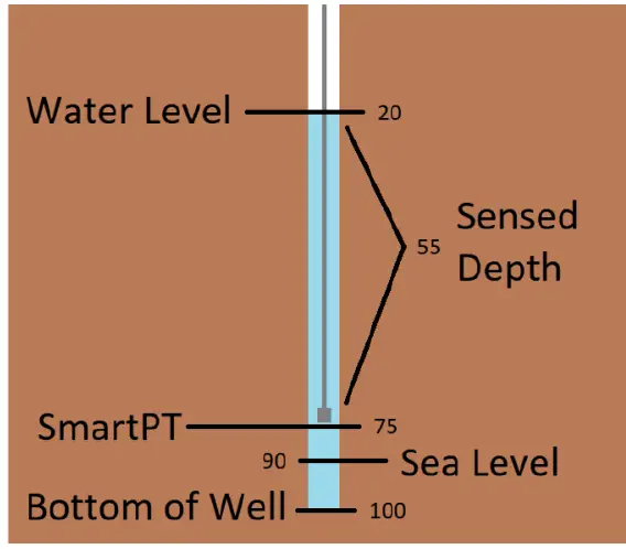
In this example, a Smart PT is installed in a 100-foot borewell, 75 feet from the top of the casing. The bottom of the well is 10 feet below sea level. Without any special configuration, the Smart PT will report the sensed depth, of 55 feet. To report feet above sea level, set the “offset” parameter to 15. The Smart PT will report the sensed depth plus the offset, for a reported value of 70. aXW_OFFSET_15! To report the distance from water to the top of the casing, set “toc” to 75. The Smart PT will return the “TOC” value minus sensed depth, for a reported value of 20. aXW_TOC_75! To report distance from the water surface to the bottom of the well, set “offset” to 25. The Smart PT will return the sensed depth plus the offset, for a reported value of 80.
Restoring the Smart PT to the default configuration
It may be useful to restore the Smart PT to the factory default configuration.
Using the Smart Sampling features and digital crest gage mode
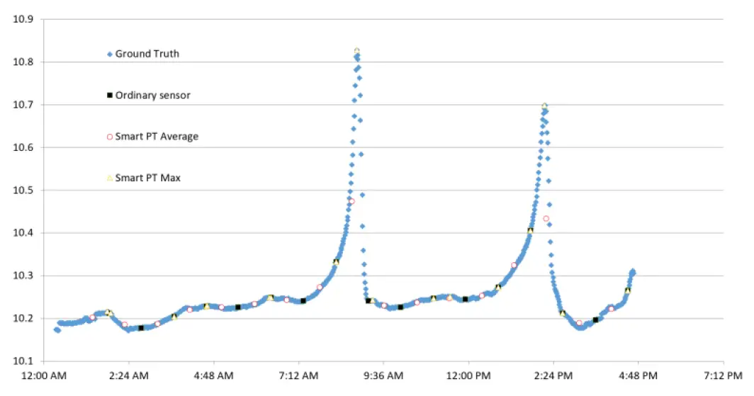
A conventional pressure sensor only samples data when requested by the logger. As seen in the chart below, if the sampling interval is set too long, there’s a risk of missing critical events. The Smart PT takes a sample once per second and can report relevant statistics on demand, including crest events. As you can see in the chart above, the Smart PT was able to accurately capture crest events that a conventional sensor would have missed. The Smart PT is also able to report average and standard deviation over the logging interval. This may be useful for integrating data from rough water and quantifying surface roughness. Instead of a sliding window, the Smart PT uses a numerically stable online variance algorithm (Welford 1962) to maintain the mean and standard deviation since the last time those values were queried.
Example configurations for the average and daily maximum
To record the ten-minute average, configure the data logger to sample the M2 command once every ten minutes. To record the daily maximum, configure the data logger to sample the M1 command once every 24 hours. Minimum and maximum values are backed-up to flash and will persist if the sensor loses power.
Using Excel to extract timestamped crest values from a data set
The Smart PT reports the time at which a min or max event occurred in the 3rd and 4th fields of the M1 response. These values, tMin and tMax, show how many seconds ago the event occurred. In the example below, a crest event occurred at 8:24:20 AM. The sensor was polled by a datalogger at 8:30.00 AM, at which time the sensor reported the crest event as happening 340 seconds in the past.
Modbus RTU
Addressing
Each Modbus sensor must have its own unique address. The default address is “1”
Power Saving
After one second without Modbus activity, the Smart PT enters a power-saving standby state. To wake the Smart PT, send any Modbus command. The Smart PT will not respond to the wake command, but it will be awake and ready to receive further commands. After one second without any activity, the Smart PT will return to the standby state.
Baud rate and com settings
Communications settings are fixed at 19200 baud, 8 data bits, no stop bit, and no parity.
Request readings
To read data from the Smart PT use function code 03, “read holding registers”. Data is stored as 32 bit floating point, starting at register 40001. It’s possible and recommended to read contiguous registers in a single operation.
Variation in the last digits of pressure readings
Smart PT reports pressure results to a precision of 0.0001 bars or better. This ensures that each pressure range of the Smart PT will return results with the same number of significant figures. Because this level of precision is higher than either the accuracy or the inter-reading stability of the Smart PT, it’s normal to see a variation in the last few digits of the pressure reading.
Set and Get the configuration
The Smart PT has many configuration objects. Objects are stored either as 32-bit floating point values or as null-terminated strings. Each configuration object is allocated 16 Modbus registers, allowing for strings of up to 31 characters. To get a configuration object from the Smart PT use function code 03, “read holding registers” To write a configuration object to the Smart PT use function code 16, “write multiple holding registers” It’s not possible to read or write multiple configuration objects with a single Modbus command.
| Command | Response | Description |
| aXD_*! | arestore factory configuration… | Restore the sensor to a factory default state
Stored data will be lost. Sensor retains factory calibration. |
A few of the string-type objects – TUNITS and PUNITS – are writable. There is no standard for transmitting strings in Modbus. This translation table allows writing a float to those objects.
Metadata Commands
Revision 1.4 of the SDI-12 specification, released in May of 2017, adds a set of commands to access metadata – descriptions of the returned data including SHEF codes and units. The Smart PT sensor implements the 1.4 specifications.
Calculation of depth
Depth is computed as follows
Reported Depth (m) = Sensed Depth (m) * (9.80665 / Gravity) * (1000 / Density) Density automatically has temperature correction applied. If the density value is set by the user, the user-defined value will override the temperature-corrected value. Smart PT temperature corrected density equation:Density = (999.83952 + 16.945176 * t – .0079870401 * t2 – 0.000046170461 * t3 + 0.00000010556302 * t4 – 0.00000000008054253 * t5) / ( 1 + .016897850 * t )
| Modbus Register Address | Description | Equivalent SDI-12 “M” Command | Equivalent SDI-12 Data Field |
| 40001 | Most recent pressure or depth reading, updated once/second | 0 | 0 |
| 40003 | Most recent temperature reading, updated once/second | 0 | 1 |
| 40017 | Minimum pressure or depth since last request for this value | 1 | 0 |
| 40019 | Seconds elapsed since last minimum pressure or depth | 1 | 1 |
| 40021 | Seconds elapsed since last maximum pressure or depth | 1 | 2 |
| 40023 | Maximum temperature since last request for this value | 1 | 3 |
| 40033 | Average pressure or depth since last request for this value | 2 | 0 |
| 40035 | Standard deviation of pressure or depth since last request for this value | 2 | 1 |
| 40037 | Number of samples used to calculate Average and Standard Deviation | 2 | 2 |
If the top of the casing is zero (the default value),
| Configuration Object | Description | Modbus Register Address | Type | Writable |
| BUILD | Date of firmware build | 41001 | NULL-Terminated String | N |
| SERIAL | Serial number | 41009 | NULL-Terminated String | N |
| ADDRESS | SDI-12 address | 41017 | NULL-Terminated String | N |
| MODADDR | Modbus address | 41025 | Floating Point | Y |
| CYCLES | # of power cycles | 41033 | Floating Point | N |
| RATE | Auto sampling interval in seconds | 41041 | Floating Point | Y |
| 485STAY | RS-485 stay awake | 41049 | Floating Point | Y |
| GRAVITY | Gravitational acceleration, used in depth calculation | 41057 | Floating Point | Y |
| DENSITY | Fluid density, used in depth calculation | 41065 | Floating Point | Y |
| PUNITS | Pressure or depth units | 41073 | NULL-Terminated String | Y |
| TUNITS | Temperature units | 41081 | NULL-Terminated String | Y |
| Configuration Object | Description | Modbus Register Address | Type | Writable |
| GRANUL | Pressure granularity, used to calculate # of significant digits for pressure and depth readings | 41089 | Floating Point | N |
| OFFSET | Offset, used in depth calculation | 41097 | Floating Point | Y |
| TOC | Top of casing, used in depth calculation | 41105 | Floating Point | Y |
| CALSLP | Calibration data | 41121 | Floating Point | N |
| CALYCPT | Calibration data | 41129 | Floating Point | N |
| MIN | Backup for crest function | 41177 | Floating Point | Y |
| MAX | Backup for crest function | 41185 | Floating Point | Y |
| MINTIME | Backup for crest function | 41193 | Floating Point | Y |
| MAXTIME | Backup for crest function | 41201 | Floating Point | Y |
| LIFEMIN | Lifetime minimum temperature, used for warranty purposes | 41209 | Floating Point | N |
| LIFEMAX | Lifetime minimum temperature, used for warranty purposes | 41217 | Floating Point | N |
| VENT | VT’ or ‘NV’, used to disable depth readings for non-vented sensors | 41225 | NULL-Terminated String | N |
| CALDATE | Date of last calibration | 41249 | NULL-Terminated String | N |
Reported Depth = Sensed Depth + Offset
| Value to Send | String Translation |
| 10 | BAR |
| 11 | MBAR |
| 12 | KPA |
| 13 | HPA |
| 14 | PA |
| 15 | PSI |
| Value to Send | String Translation |
| 16 | TORR |
| 20 | M |
| 21 | CM |
| 22 | MM |
| 23 | FT |
| 24 | IN |
| 30 | DC |
| 31 | DF |
| 32 | DK |
| aIM0! | a00002 |
| aIM0_001! | 0, PW, BAR, pressure; |
| aIM0_002! | 0, TW, DC, temperature; |
If the top of the casing is greater than zero, the sensed depth is subtracted from the top of the casing: Reported Depth = Top of Casing – Sensed Depth + Offset


