![]()
CHANGING YOUR LANDSCAPE SINCE 1945
swisherinc.com
OWNER’S MANUAL 19920
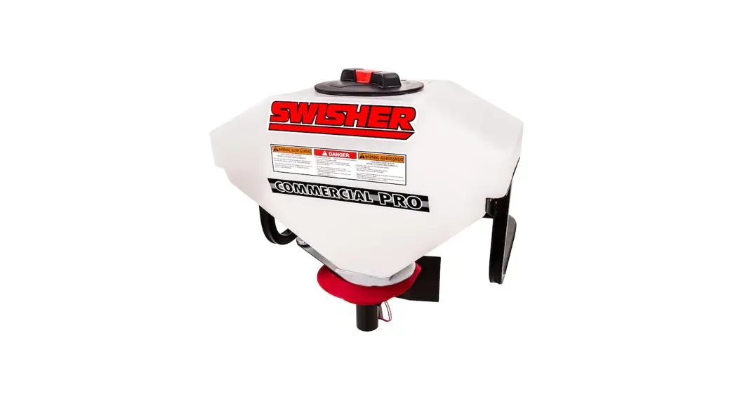
Commercial Pro ATV Spreader
Starting Serial #: L215-001001
19920 Capacity Broadcast Tow-Behind Spreader
IMPORTANT![]() Read and follow all Safety Precautions and Instructions
Read and follow all Safety Precautions and Instructions
Before Operating this Equipment.
6/21/2021
SWISHER
1602 CORPORATE DRIVE, WARRENSBURG, MISSOURI 64093
PHONE 660-747-8183 FAX 660-747-8650
Made InThe USA of US and Global Parts
19919 REV 21-165
LIMITED WARRANTY
The manufacturer’s warranty to the original consumer purchaser is: This product is free from defects in materials and workmanship for a period of one (1) year from the date of purchase by the original consumer purchaser. We will repair or replace, at our discretion, parts found to be defective due to materials or workmanship. This warranty is subject to the following limitations and exclusions:
- Limitation
This warranty applies only to products which have been properly assembled, adjusted, and operated in accordance with the instructions contained within this manual. This warranty does not apply to any product of Swisher that has been subject to alteration, misuse, abuse, improper assembly or installation, shipping damage, or to normal wear of product. - Exclusions
Excluded from this warranty are normal wear, normal adjustments, and normal maintenance.
In the event you have a claim under this warranty, you must return the product to an authorized service dealer. All transportation charges, damage, or loss incurred during transportation of parts submitted for replacement or repair under this warranty shall be borne by the purchaser. Should you have any questions concerning this warranty, please contact us toll-free at 1-800-222-8183. The model number, serial number, date of purchase, and the name of the authorized Swisher dealer from
whom you purchased the product will be needed before any warranty claim can be processed.
THIS WARRANTY DOES NOT APPLY TO ANY INCIDENTAL OR CONSEQUENTIAL DAMAGES AND ANY IMPLIED WARRANTIES ARE LIMITED TO THE SAME TIME PERIODS STATED HEREIN FOR ALL EXPRESSED WARRANTIES. Some states do not allow the limitation of consequential damages or limitations on how long an implied warranty may last, so the above limitations or exclusions may not apply to you. This warranty gives you specific legal rights and you may have other rights, which vary from state-to-state. This is a limited warranty as defined by the Magnuson-Moss Act of 1975.
SAFETY PRECAUTIONS
![]() This Safety Alert Symbol indicates important messages in this manual. When you see this symbol, carefully read the message that follows and be alert to the possibility of personal injury.
This Safety Alert Symbol indicates important messages in this manual. When you see this symbol, carefully read the message that follows and be alert to the possibility of personal injury.
Read this manual completely. Failure to observe the following safety instructions could result in serious injury or death.
- Read the manual. Learn to operate the attachment safely.
- Keep the operating speed low!
- Allow only responsible adults who are familiar with these instructions to operate this attachment. Never allow children to operate this attachment.
- Be sure the area is clear of other people before operating. Children are often attracted to the attachment and the operating activity. Never assume that children will remain where you last saw them. Keep children under the watchful care of another responsible adult.
- Watch for traffic when operating near or while crossing roadways.
- Do not operate the attachment if it has been dropped or damaged in any manner.
Repair as necessary. - Stop and inspect the attachment if you strike an object. Repair as necessary before restarting.
- Dress properly. Do not operate when barefoot or wearing open sandals.
- Do not operate the attachment while under the influence of alcohol or drugs.
- Never tamper with safety devices. Check their proper operation regularly.
- Operate attachments up and down slopes. There is a significant risk of overturns when operating across slopes.
- Never make adjustments or repairs with the vehicle engine running.
- Follow the vehicle manufacturers safe operating procedures.
Recommended Tools For Assembly:
- Socket Wrench
- 9/16” Socket
- ½” Socket
- 9/16” Box End Wrench
- ½” Box End Wrench
- Small Flat Head Screwdriver
- Pliers
| Item # | Part # | Description |
| 1 | 10192 | Washer – Nylon Retainer 5/16 |
| 2 | 19903Z | Bracket – Upper Motor Suppo |
| 3 | 19902Z | Gate – Hopper |
| 4 | 22605 | Washer – USS Flat, 1/2 |
| 5 | 7825Z | Bushing |
| 6 | 22610 | Spring – Gate |
| 7 | 22606 | Washer – 5/16 X 1 1/4 OD |
| 8 | 10113 | Deflector |
| 9 | 22607 | Washer – USS Flat, 5/16 |
| 10 | 22608 | Bolt – 5/16-18 X 1 1/2 |
| 11 | 22609 | Nut – Nyloc 5/16-18 |
| 12 | 10110 | Hopper |
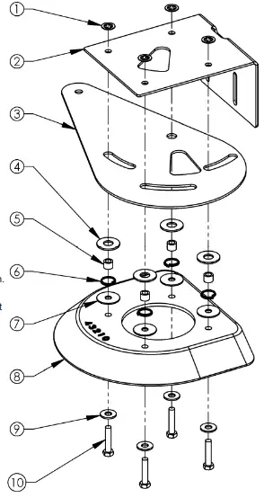
Step 1: Hopper Gate Assembly
- Assemble the Deflector (8), Hopper Gate (3) and Upper
Motor Support Bracket (2) together using four 5/16-18 X 1 ½” Bolts (10), four 5/16” Washers (9), four 5/16” X 1 ¼” Washers (7), four Springs (6), four Bushings (5), four ½” Washers (4) and four 5/16” Nylon Retainer Washers (1) in the order shown - Tip: Use the 5/16” Nylon Retainer Washers (1) to hold the assembly together for the next step. The three slots and pivothole of the Hopper Gate (3) need to be aligned with the Bushings (5) so it can freely rotate.
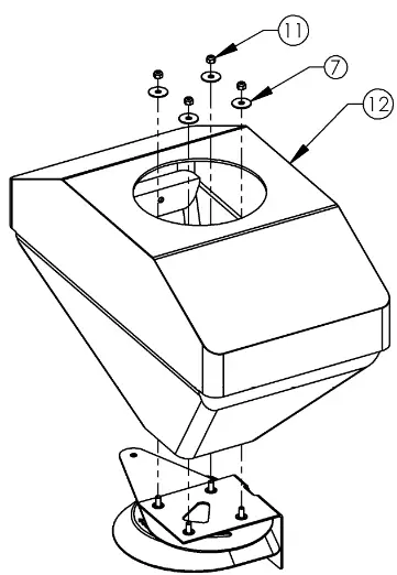
Step 2: Attaching the Hopper Gate Assembly
- Using a ½” socket wrench and a ½” box end wrench, attach the assembly made in Step 1 to the Hopper (12) by sliding the four 5/16-18 X 1 ½” Bolts (10) through the holes in the bottom of the Hopper (12). Place a 5/16” X 1 ¼” Washer (7) over each 5/16-18 X 1 ½” Bolt (10) and securely fasten the assembly with the 5/16-18 Nuts (11).
- Tip: Make sure the Hopper Gate (3) is able to pivot smoothly.
If it doesn’t pivot smoothly, the Bushings (5) installed in Step 1 may not be correctly aligned. Check to make sure the
Bushings (5) are correctly aligned with the three slots and pivot hole of the Hopper Gate (3) by pressing down on the sides of the Hopper Gate (3). You should feel resistance from the Springs (6), indicating proper alignment.
Step 3: Motor Assembly
- Tip: Items 3, 4 and 5 are preassembled.
- Remove the Snap Ring (1) from the Motor (5) using a small flat head screwdriver. Slide the Spinner Disc (2) onto the Motor Shaft and secure with the Snap Ring. If the snap ring is difficult to install by hand, use a pair of pliers to install it.
- Insert the 5/16-18 X 1” Carriage Bolts (6) through the square holes of the Lower Motor Bracket (4), through the slots of the Upper Motor Bracket (2 on pg 4) and through the Spreader Shield (8). The guide on the Lower Motor Bracket (4) will slide up through the slot in the Upper Motor Bracket (2 on pg 4) . Fasten the 5/16-18 X 1” Carriage Bolts (6) using the T-Knobs (9) and tighten securely.
- Route the wires of the Motor (5) through the Black Zip Tie (7).
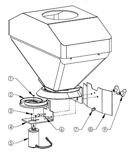
When ordering replacement parts
*USE PAINT CODE: TK=BLACK
Note: To control the spread width, loosen the T-Knobs (9) and slide the Motor Assembly up or down. In the uppermost adjustment the material will be deflected down by the Deflector (8 on pg 4) resulting in a narrower spread width. To increase the spread width, slide the Motor Assembly down and away from the Deflector. For more information, see the Material Spreading Chart on pg 11.
| Item # | Part # | Description |
| 1 | N/A | Snap Ring (Included w/ Motor) |
| 2 | 10118 | Disc – Spinner |
| 3 | 12564 | Nut – Nyloc, 10-32 |
| 4 | 10114* | Bracket – Motor Support, Lower |
| 5 | 19913 | Motor – Spreader, 12V |
| 6 | 10197 | Bolt – Carriage 5/16-18 X 1 |
| 7 | AS021 | Tie, Black 5 1/2″ |
| 8 | 10117* | Shield – Spreader |
| 9 | 3844 | Knob – T, 5/16-18 |
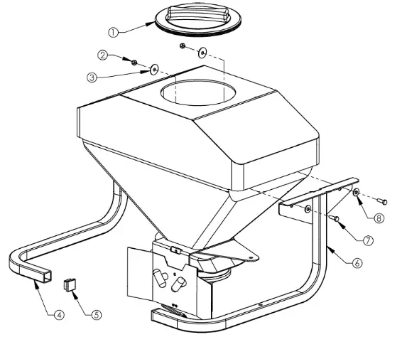
| Item # | Part # | Description |
| 1 | 10176 | Lid – Hopper |
| 2 | 22609 | Nut – Nyloc 5/16-18 |
| 3 | 22606 | Washer – 5/16 X 1 1/4 OD |
| 4 | 19910* | Weldment – Hopper Support, Left |
| 5 | 10105 | Plug – 1 1/4 Cap, Square |
| 6 | 19909* | Weldment – Hopper Support, Right |
| 7 | NB501 | Bolt – 5/16-18 X 1 |
| 8 | 22607 | Washer – USS Flat, 5/16 |
Step 4: Attaching the Hopper Support Tubes
- Attach the Support Tube Weldments (4 & 6) to the Hopper (12 on pg 4) by inserting the 5/16-18 X 1” Bolts (7) through the smaller 5/16” Washers (8) and weldment, and into the holes on the side of the Hopper (12 on pg 4) as shown.
- Place a 5/16 X 1 1/4” Washer (3) over each 5/16-18 X 1” Bolt (7) on the inside of the Hopper and thread the 5/16-18 Nuts (2) onto the 5/16-18 X 1” Bolts (7), tightening securely using a ½” socket wrench and ½” box end wrench.
- Tip: Item 5 is preassembled into the tube weldments.
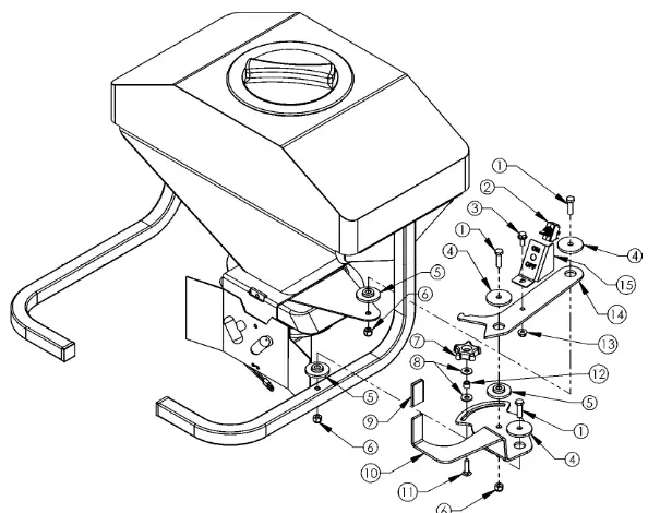
Step 5: Handle & Linkage Assembly
- Using a ½” socket wrench and a ½” box end wrench, connect the On/Off Switch Bracket (15) to the Indicator Linkage (14) using one 5/16-18 X ¾” Bolt (3) and one 5/16-18 Nut (13) and tighten securely.
- Using a 9/16” socket wrench and a 9/16” box end wrench, connect the Indicator Linkage (14) to the Hopper Gate (3 on pg 4) with one Large Bushing (5), one Large Washer (4), one 3/8-16 X 1 ¼” Bolt (1) and one 3/8-16 Nut (6).
- Using a 9/16” socket wrench and a 9/16” box end wrench, connect the Pivot Handle (10) to the Right Hopper Support Weldment (6 on pg 6) with one Large Bushing (5), one Large Washer (4), one 3/8-16 X 1 ¼” Bolt (1) and one 3/8-16 Nut (6).
- Tip: The socket fits through the large hole on the bottom of the Right Hopper Support Weldment (6 on pg 6).
- Connect the Indicator Linkage (14) to the Pivot Handle (10) with one Large Bushing (5), one Large Washer (4), one 3/8-16 X 1” Bolt (1) and one 3/8-16 Nut (6) using a 9/16” socket wrench and a 9/16” box end wrench.
- Insert the 5/16-18 X 1 ¼” Carriage Bolt (11) through the bottom of the slot in the Pivot Handle (10). Add one 5/16” Washer (8), one Bushing (12), another 5/16” Washer (8) and the Black Knob (7) to secure the 5/16-18 X 1 ¼” Carriage Bolt (11).
- Tip: The Handle Grip (9) is preassembled on the Pivot Handle (10).
- Tip: The Toggle Switch (2) is preassembled on the Motor Wiring Harness (3 on pg 10) and will be installed on the On/Off Switch Bracket (15) in Step 8.
| Item # | Part # | Description |
| 1 | NB618 | Bolt – 3/8-16 X 1 1/4 |
| 2 | 19912 | Switch – Toggle On/Off |
| 3 | NB596 | Bolt – Serr Flange, 5/16-18 X 3/4 |
| 4 | 6040Z | Washer – Large |
| 5 | 6037 | Bushing – Large |
| 6 | NB182 | Nut – Nyloc 3/8-16 |
| 7 | 2030 | Knob – Black |
| 8 | 22607 | Washer – USS Flat, 5/16 |
| 9 | 19911 | Pivot – Handle Grip |
| 10 | 19907Z | Handle – Pivot |
| 11 | 10217 | Bolt – Carriage 5/16-18 X 1.25 |
| 12 | 7825Z | Bushing |
| 13 | NB170 | Nut – Serr Flange 5/16-18 |
| 14 | 19906Z | Linkage – Indicator |
| 15 | 19201* | Bracket – ON/OFF Switch |
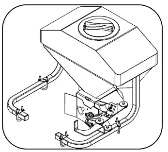
![]() Step 6: Attaching the Spreader to Your ATV Rack
Step 6: Attaching the Spreader to Your ATV Rack
- Tip: Find an assistant to help when attaching or removing the ATV Spreader. Care must be taken while lifting to avoid personal injury or equipment damage.
- Position the ATV Spreader so that the tubes line up with the existing ATV rack. Slide the U-Bolts (2) up through the bottom of the ATV rack and place the U-Bolt Plate (3) over the U-Bolt (2) and on top of the ATV Spreader tubes as shown. Using a ½” socket wrench, fasten the 5/16-18 Nuts (4), tightening them securely.
- Tip: For customers with composite racks, we have provided Mount Plates (1) that can be used underneath the rack and positioned so that the force exerted by the U-Bolts (2) is spread out over the surface area of the rack.
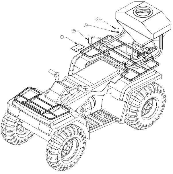
| Item # | Part # | Description |
| 1 | 10179* | Plate – Mount |
| 2 | 10109 | U Bolt – 5/16-18 X 1 3/8 X 3 5/8 |
| 3 | N/A | Plate – U-Bolt (Included w/ U-Bolt) |
| 4 | NB181 | Nut – Nyloc 5/16-18 |
| Item # | Part # | Description |
| 1 | 2030 | Knob – Black |
| 2 | 19928 | Decal – Indicator, 0-4 |
| 3 | 19907Z | Handle – Pivot |
| 4 | 19906Z | Linkage – Indicator |
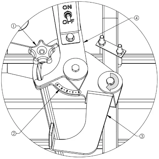
Step 7: Calibrating the Indicator Decal
- Rotate the Pivot Handle (3) clockwise as you’re looking down at it, until the Hopper Gate (3 on pg 4) is fully closed.
- Place the Indicator Decal (2) on the Pivot Handle (3) by lining up the 0 with the end of the Indicator Linkage (4).
- Tip: To change the amount of material being spread, adjust the opening of the Hopper Gate (3 on pg 4) by rotating the Pivot Handle (3) until the desired flow is attained. As you’re looking down at the assembly, rotate clockwise to reduce the flow and counter clockwise to increase the flow. The Indicator Decal (1) shows a scale of 0 to 4, with 4 indicating fully open and 0 indicating fully closed.
- Tip: The Black Knob (1) can be used to lock the Bushing (12 on pg 7) at infinite points along the slot of the Pivot Handle (3). This will allow you to open the Hopper Gate to the same point every time, giving you more consistent flow rates.
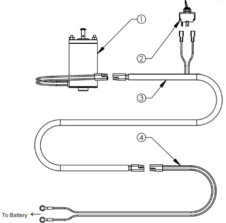
Step 8: Wiring Harness Assembly
- Tip: Items 2 and 3 are preassembled. The red wires can be hooked up to the terminals of the Toggle Switch (2) interchangeably.
- Remove the two nuts from the Toggle Switch (2). The black plastic nut will be able to be removed by hand. The metal nut may require the use of a 9/16” box end wrench.
- Install the Toggle Switch (2) to the On/Off Switch Bracket (15 on pg 7). There is a keyway on the Toggle Switch (2) that mates to the key in the corresponding hole on the front of the On/Off Switch Bracket (15 on pg 7). Thread the metal nut and tighten using a 9/16” box end wrench. Thread the black plastic nut and finger-tighten it against the first nut.
- Connect the Motor (1) to the Motor Wiring Harness (3) by interlocking the molded connectors. Make sure to connect the end of the Motor Wiring Harness (3) closest to the Toggle Switch (2) as shown in the diagram below.
- Tip: Use the Black Zip Tie (7 on pg 5) to secure the wires of the Motor (1) to the Spreader Shield (8 on pg 5).
- Connect the ring terminals of the Battery Wiring Harness (4) to the battery posts. Be sure to connect the red wire to the positive post and the other wire to the negative post.
- Connect the Motor Wiring Harness (3) to the Battery Wiring Harness (4) by interlocking the molded connectors.
- Tip: Use the two white zip ties found in the hardware bag to secure the Motor Wiring Harness (3) to the Spreader.
| Item # | Part # | Description |
| 1 | 19913 | Motor – Spreader, 12V |
| 2 | 19912 | Switch – Toggle On/Off |
| 3 | 19915 | Harness – Wiring, Motor |
| 4 | 19917 | Harness – Wiring, Battery |
Material Spreading Chart
(Calibrated at 4 mph Ground Speed)
| P roduc t | S e tting 1 | S e tting 1.5 | S e tting 2 | S e tting 2 .5 | S e tting 3 | S e tting 3 . 5 | S e tting 4 |
| lbs/Acre | lbs/Acre | lbs/Acre | lbs/Acre | lbs/Acre | lbs/Acre | lbs/Acre |
| Fertilizer | N/A | 124 ©4 mph | 246 ©4 mph | 458 ©4 mph | N/A | N/A | N/A |
| N/A | 62 ©8 mph | 123 ©8 mph | 229 ©8 mph | N/A | N/A | N/A |
| Rock Salt | N/A | 110 ©4 mph | 260 ©4 mph | 500 ©4 mph | 762 ©4 mph | 1056 ©4 mph | 1312 ©4 mph |
| N/A | 55 ©8 mph | 130 ©8 mph | 250 ©8 mph | 381© 8 mph | 528 ©8 mph | 656 ©8 mph |
| Dry Sand | 144 ©4 mph | 488 ©4 mph | 880 ©4 mph | N/A | N/A | N/A | N/A |
| 72 ©8 mph | 244 ©8 mph | 440 ©8 mph | N/A | N/A | N/A | N/A |
| Red Fescue | N/A | 40 ©4 mph | 102 ©4 mph | 154 ©4 mph | N/A | N/A | N/A |
| N/A | 20 ©8 mph | 51© 8 mph | 77 ©8 mph | N/A | N/A | N/A |
– The above Spreader Chart settings are based off of a 10’ spread width. Always trial test the application rate.
– Depending on the material you are spreading, the spread width could be higher or lower than what is shown.
– All measurements are taken with the Motor Assembly at the furthest setting from the Deflector (see pg 5).
– Formula for calibration of other products not listed above:

Flow Rate (lbs/min): Material (lbs/min) that flows through selected hopper gate setting per minute (Motor Assembly removed, see pg 5).
Coverage (sq-ft/min): Material spread width (trial test required) multiplied by the distance traveled per minute (4 mph = 352 ft/min; 3 mph = 264 ft/min; 2 mph = 176 ft/min; 1 mph = 88 ft/min).
Helpful Tips
- Read Owner’s Manual before use and be sure to follow all safety label precautions provided on the Spreader Hopper.
- Always use ONLY CLEAN DRY MATERIAL and be sure the remove all unused material from the Hopper after each use. Damp materials will cause material flow problems and material freezing problems in cold temperatures.
- Be sure material is free of foreign matter such as packaging etc.
- Some materials may jam the Hopper Gate at lower settings so it may be necessary to use a larger setting and increase your mph to compensate for the increased material flow rate. Increasing your ground speed from 4 mph to 8 mph will decrease your application rate per acre by half if the same setting is used at both speeds.
- Light seed such as Kentucky Blue Grass can be mixed with a seed such as clover to aid in material flow at a 50/50 mix.
- Increased material density per acre can be achieved by adjusting the Motor Assembly closer to the Deflector and Hopper Gate. This accomplishes a narrower spread width, providing more lbs/sq-ft of material.
- Do not spread light seed in windy conditions as poor coverage will result.
- Proper material coverage is achieved with the greatest satisfaction by covering the desired area twice at half the recommended application rate indicated by the manufacturer of the material. Once by traveling length ways then by traveling cross ways to account for any underlap issues. The adjustment of the application rate can be made either by adjusting the Hopper Gate to a lesser setting or by increasing the ground speed of the application vehicle.
- When using the Spreader for salt/ice melts, fertilizer or other corrosive materials it is imperative that the Spreader is thoroughly cleaned to prevent corrosion causing premature failure of the product.
WHEN ORDERING PARTS, PLEASE HAVE THE FOLLOWING INFORMATION AVAILABLE:
* PRODUCT – ________________
* SERIAL NUMBER – _______________
* MODEL NUMBER – _______________
TYPE – _______________
* PART NUMBER WITH PAINT CODE
* PART DESCRIPTION
TELEPHONE – 1-800-222-8183
FAX – 1-660-747-8650
SWISHER
1602 CORPORATE DRIVE
WARRENSBURG, MO 64093
swisherinc.com
SWISHER
1602 CORPORATE DRIVE, WARRENSBURG, MISSOURI 64093
PHONE 660-747-8183
FAX 660-747-8650


