![]()
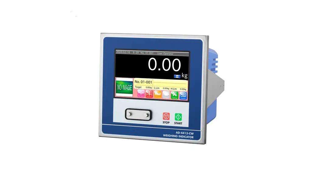
AD-4412-CW
Weighing Indicator
CONNECTION SETTING EXAMPLE
1WMPD4004155
© 2020 A&D Company, Limited. All rights reserved. No part of this publication may be reproduced, transmitted, transcribed, or translated into any language in any form by any means without the written permission of A&D Company, Limited.
The contents of this manual and the specifications of the instrument covered by this manual are subject to change for improvement without notice.
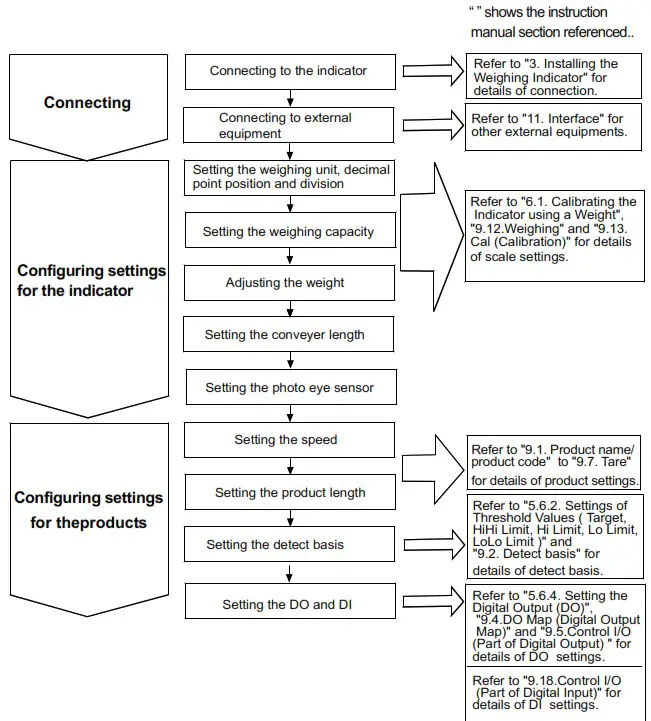
This section shows descriptions from connection to basic settings for using the AD-4412-CW as a weight checker.
Setting flow Instruction manual
Connecting
Connecting to the indicator
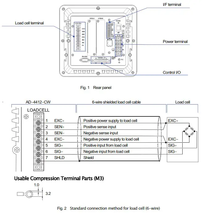
The following describes how to connect the indicator to the load cell.
Follow the procedure below for the indicator connection.
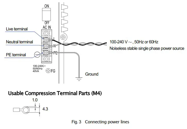
- Connect the load cell cable to the “LOAD CELL” terminal (Fig. 2), the indicator’s power cable to the “AC IN” terminal (Fig. 3), both located on the rear panel of the indicator. (Refer to “3.4. Connecting Load Cell Cables” and “3.5. Connecting Power Lines” in the instruction manual.)
- When using the photo eye sensor, connect it to the “I/F” terminal on the rear panel of the indicator. (Refer to “Connection of Photo eye Sensor” of “11. Interface” in the instruction manual.)

 Warning
Ground the indicator to avoid an electric shock or operation error. If the indicator is not grounded, it may cause an electric shock or malfunction due to discharge of static electricity.
Connecting the external equipment
This section describes the specifications and connection examples for control I/O.
Control I/O specifications
Control I/O has DO11 points, DI11 points, and the following specifications.
Table 1 Control I/O Interface specifications
| Input circuit (DI) method | Non-voltage input/open collector drive |
| Input terminal open valtage | 7 to 11 V |
| Input circuit drive current | 5 mA (max.) |
| Max. residual voltage | 2V (max.) |
| Output circuit (DO) method | Open collector |
| Output circuit withstand voltage | DC 40 V |
| Max. drive current | 50 mA |
| Output terminal residual voltage | 1.5 V (at drive current 50 mA) |
Connecting the control I/O
Refer to the following figure for connecting the control I/O.
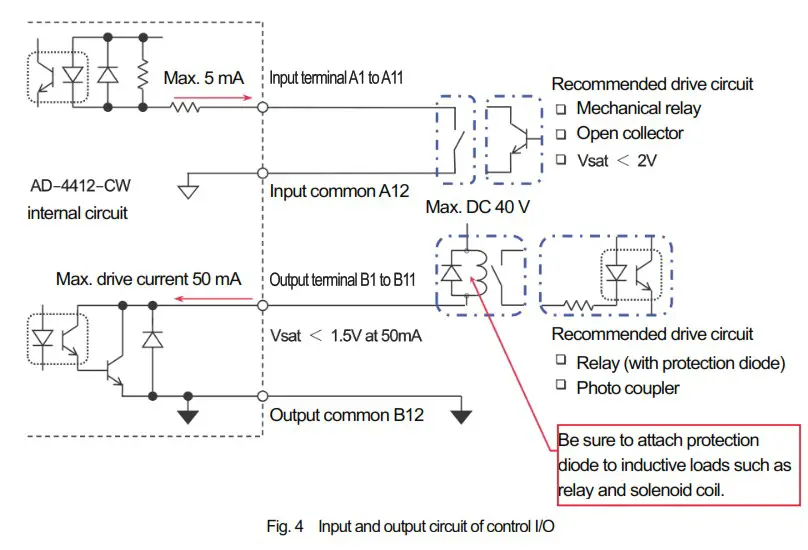
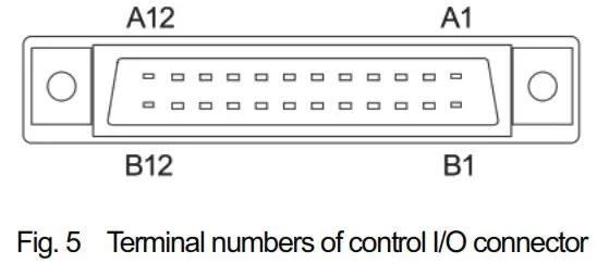
Table 2 Correspondence table of control I/O and DI/DO
| Input terminal | DI number | Output terminal | DO number |
| Al | DI 1 | B1 | DO 1 |
| A2 | DI 2 | B2 | DO 2 |
| A3 | DI 3 | B3 | DO 3 |
| A4 | DI 4 | B4 | DO 4 |
| AS | DI 5 | B5 | DO 5 |
| A6 | DI 6 | B6 | DO 6 |
| A7 | DI 7 | B7 | DO 7 |
| AS | DI 8 | B8 | DO 8 |
| A9 | DI 9 | B9 | DO 9 |
| A10 | DI 10 | B10 | DO 10 |
| All | D111 | B11 | D011 |
| Al2 | (nputccelmon) | B12 | (output =inn) |
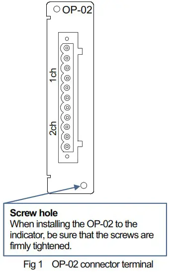
* Optional OP-02 Relay output and OP-05 parallel I/O can be installed in the indicator for a total of up to two units.
However, corresponding numbers for the DI/DO vary depending on the slot installed to.
Installing the OP-02 Relay output into optional slot 1 allows use of DO12 to DO20. Installing the OP-02 Relay output into optional slot 2 allows use of DO28 to DO36. (Refer to “11.5. OP – 02 Relay output” in the instruction manual for details.)
| Output terminal | DO nunter ( optional slot 1) | DO nirnber ( optional slot 2) | |
| lch | 1 | DO 12 | DO 28 |
| 2 | DO 13 | DO 29 | |
| 3 | DO 14 | DO 30 | |
| 4 | DO 15 | DO 31 | |
| 5 | DO 16 | DO 32 | |
| 6 | (otrout Gomm) | (outout common) | |
| 2ch | 7 | DO 17 | DO 33 |
| 8 | DO 18 | DO 34 | |
| 9 | DO 19 | DO 35 | |
| 10 | DO 20 | DO 36 | |
| 11 | (cutout commcn) | (output common) | |
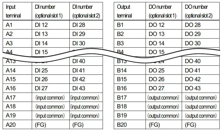
Installing the OP-05 Parallel I/O to optional slot 1 allows use of DI12 to DI27 and DO12 to DO27. Installing the OP-05 Parallel I/O to optional slot 2 allows use of DI28 to DI43 and DO28 to DO43. (Refer to “11.6. OP – 05 Parallel Input/Output” in the instruction manual for details.)
Table 4 Correspondence table of OP-05 and DI/DO
Connection example
The following shows a general connection example for the indicator. The following settings are described based on this example.
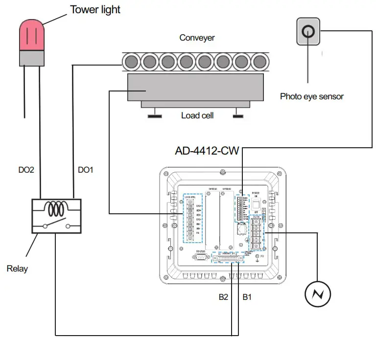
Fig. 8 Connection example
Othrer specifications
- Scale weighing capacity: 1000 g
- Conveyer length : 300 mm
- Conveyer speed : 80 m/min
Setting the indicator
By changing the factory settings for the indicator, it can be changed to have the appropriate settings for your scale. The parameters set are maintained in the memory even after shutting down the power of the indicator until the indicator is initialized or those settings are changed. The following settings require quality manager or higher permissions. (Refer to “5.5 Managing User Level for Logging In” of the instruction manual for setting the management level.)
Weighing unit, decimal point position and division
- Touch the Setting key on the weighing screen to display the setting screen.
 Fig. 9 Setting screen
 - Touch the Weighing button on “Balance” tab and set the weighing unit, decimal point position and division for weighing products into the each field on “Weighing Setting 1” tab.

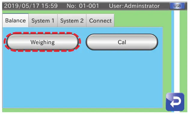 Fig. 9 Setting screen
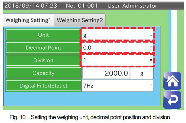
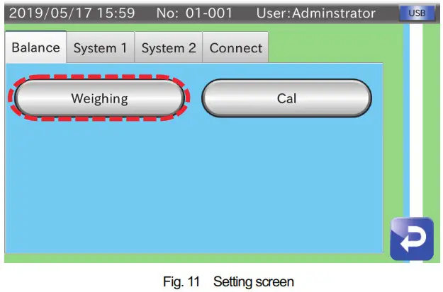
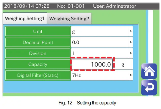
Weighing capacity
- Touch the Setting key on the weighing screen to display the setting screen.

- Touch the Weighing button on the “Balance” tab and enter an appropriate capacity (rated capacity) for your load cell into the field “Capacity” on the “Weighing Setting 1” tab. (Example below is when the 1000 g is entered as capacity.)

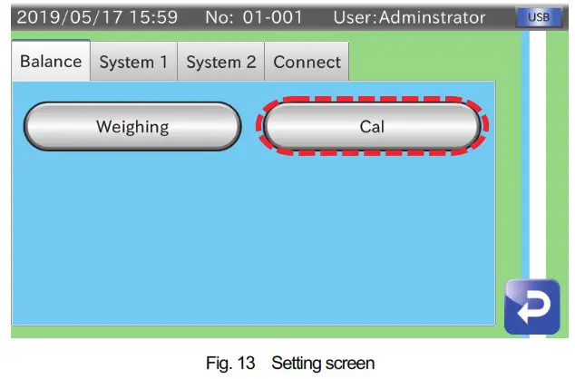
Adjusting the weight
- Touch the Setting key on the weighing screen to display the setting screen.

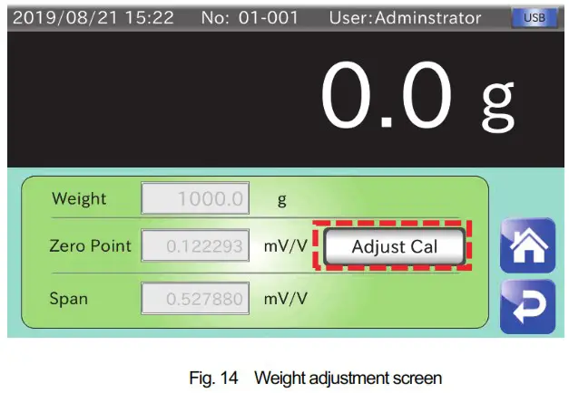
- Touch the Cal button on the “Balance” tab to display the weight adjustment screen.

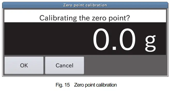
- Touch the Adjust Cal button to calibrate the zero point. Touch the OK button after confirming that nothing is placed on the load cell. To proceed to span calibration in the next step without calibrating the zero point, touch the Cancel button

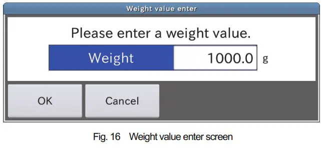
- The “Weight value enter” screen is displayed after finishing zero point calibration. Enter a mass for the weight to be used for calibration. (The weight value can be set between 0 g and capacity (g) of the load cell.)

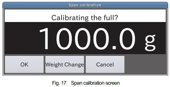
- The “Span calibration” screen is displayed after you have finished entering the weight value. Place a weight of the mass entered on the load cell. Wait until the numerical value is stabilized, and then perform the span calibration.

Conveyer length
By changing the factory settings for the indicator connected to the weight checker, settings can be changed to those appropriate for your weight checker. The parameters set are maintained in the memory even after shutting down the power of the indicator until the indicator is initialized or those settings are changed. The following settings require quality manager or higher permissions.
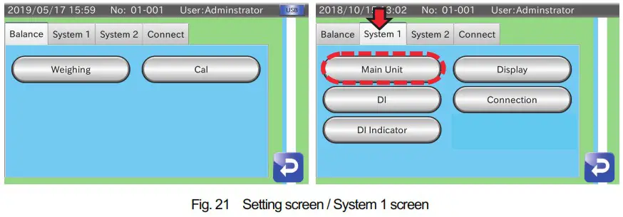
- Touch the Setting key on the weighing screen to display the setting screen.

- Touch the Main Unit button on the “System 1” tab to display the main unit setting screen.

- Set the length for your conveyer in the field “Conveyer Length” on the”Main Unit 1″ tab. (The indicator must be restarted to enable those settings.)

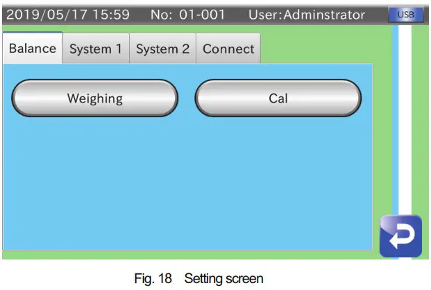
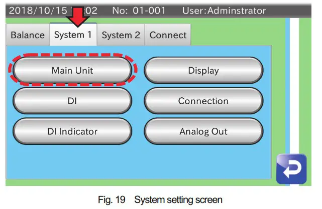
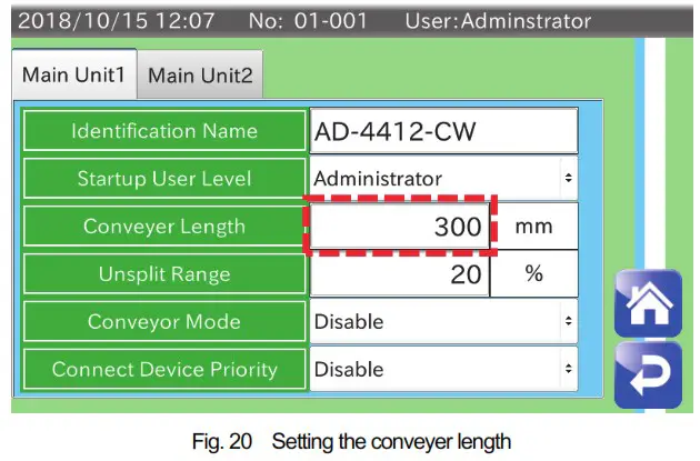
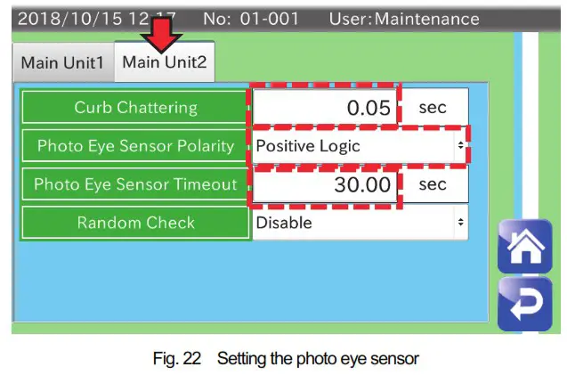
Photo eye sensor
Setting the photo eye sensor
- After connecting the photo eye sensor to the I/F terminal, touch the Setting key on weighing screen to display the setting screen. Touch the Main Unit button on “System 1” tab to display main unit setting screen.

- Set the “Curb Chattering”, “Photo Eye Sensor Polarity” and “Photo Eye Sensor Timeout” on the “Main Unit 2” tab.

Settings for products
When using the indicator as weight checker, it requires settings according to the type of products to be conveyed in order to detect and reject properly. The parameters set are maintained in the memory even after shutting down the power of the indicator until the indicator is initialized or those settings are changed. The following settings require quality manager or higher permissions.
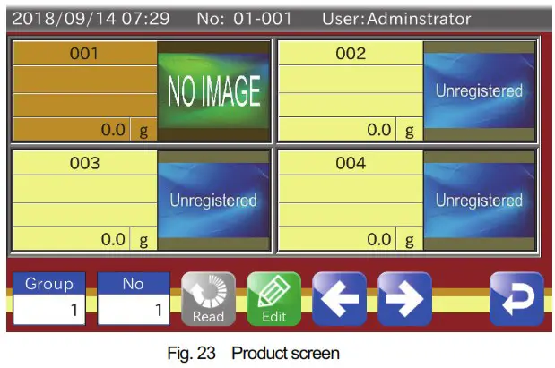
Speed
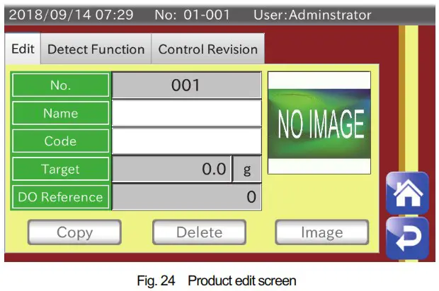
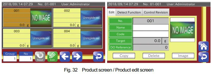
- Touch the Product key on weighing screen to display the product screen.

- Touch the Edit key on the product screen to display the product edit screen.

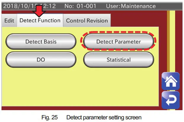
- Touch the Detect Parameter button on the “Detect Function” tab to display the weighing parameter setting screen.

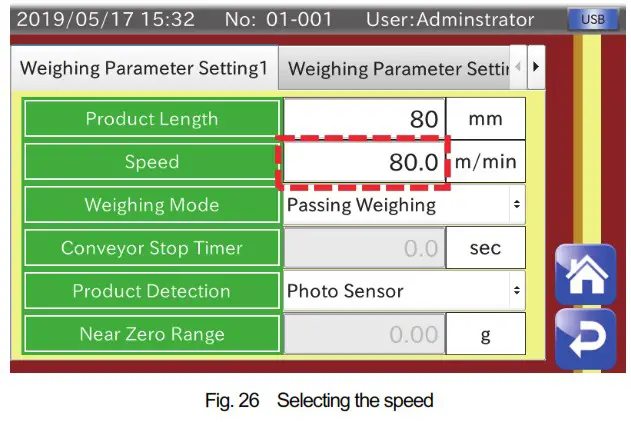
- Enter an appropriate speed for your belt conveyor in the field “Speed” on the “Weighing Parameter Setting 1” tab. (The speed for the belt conveyor must be calibrated beforehand.)

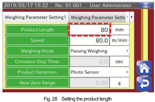
Product length
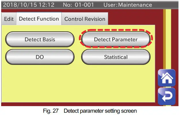
- Display the product edit screen in the same way as “3.1. Speed” described previously, and then touch the Detect Parameter button on the “Detect Function” tab to display the weighing parameter setting screen.

- Set an appropriate length for products to be conveyed in the field “Product Length” on the “Weighing Parameter Setting 1” tab. The product length is used for continuous unsplit detection. (Setting it to a value longer or shorter than the products to be conveyed may cause a detecton error.)

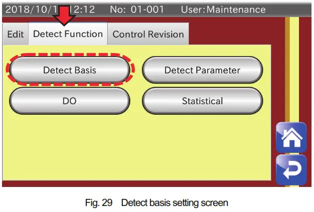
Detect basis
- Display the product edit screen in the same way as “3.1. Speed” described previously, and then touch the Detect Basis button on “Detect Function” tab to display the detect basis setting screen.

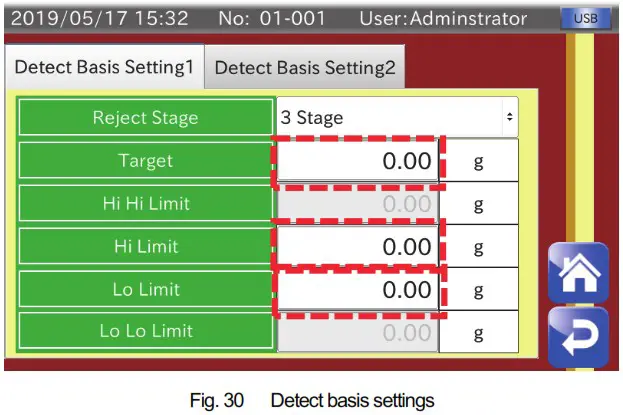
- By setting “Target”, “Hi Limit” and “Lo Limit” on the “Detect Basis Setting 1” tab, the indicator detects weighing values that exceed the upper limit (Hi Limit) as being overweight and weighing values below the lower limit as being underweight. (When setting the reject stage to stage 5, the upper-upper limit (Hi Hi Limit) value detects very overweight and lowerlower limit (Lo Lo Limit) detects very underweight by adding upper-upper limit and lower-lower limit to those settings.) Those detections can also be used as output conditions of the DO/DI. Refer to “3.4 Setting the DI/DO” for details of the setting method.
 Refer to “5.7. Summary of Weighing Result” in the instruction manual for details of summary of weighing results using the detect basis described above.
 Refer to “5.7. Summary of Weighing Result” in the instruction manual for details of summary of weighing results using the detect basis described above.
Setting the DO/DI
Setting the DO is described using the connection example shown in “1.2. Connecting the external equipment”. The example below is when an output to the conveyer is set to DO1 and an output to the tower light is set to DO2. (DO number is a number set by yourself at connection.)
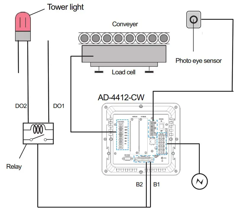
Fig. 31 Connection example
Setting the DO
- Touch the Product key on the weighing screen to display the product screen. Then, touch the Edit key on the product screen to display the product edit screen.

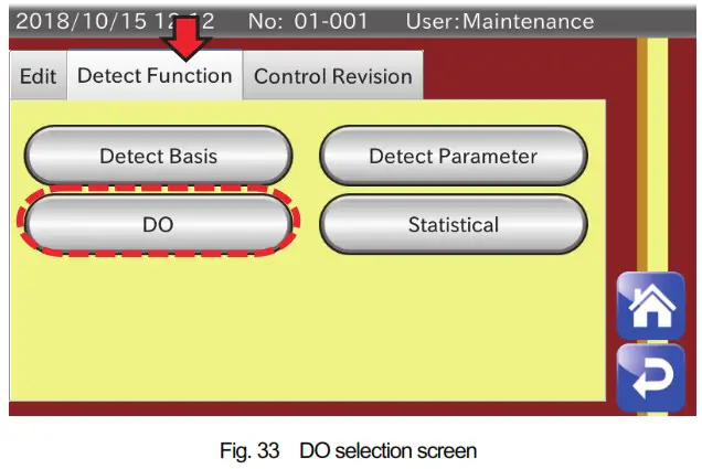
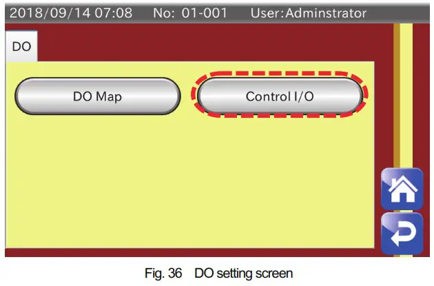
- Touch the DO button on the “Detect Function” tab to display the DO setting screen.

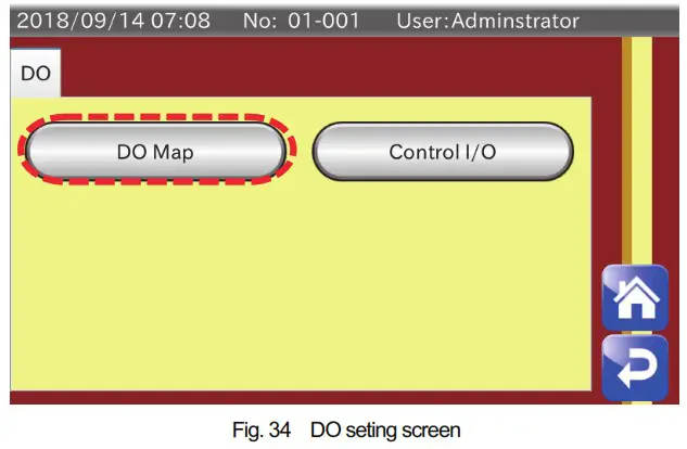
- Touch the DO Map button to display the DO map screen.

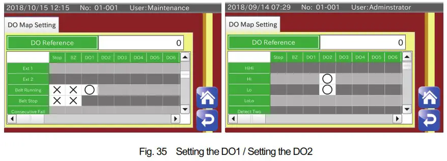
- The example is when “” is placed in the field “Belt Running” for “DO1” to operate the belt conveyer while weighing. “”is placed in the field “HiHi” and “LoLo” for “DO2” to reject products using the rejecter at upper-upper (HiHi) detection or lower-lower (LoLo) detection.

- Return to the DO setting screen and touch the AD-4412-CW button to display the DO operation setting screen.
- In this example, DO does not need to be set for the belt conveyor and tower light. However, when using a flipper, etc, set the delay time as “the time until the weighing product reaches the rejecter after detecting it at the end of the conveyer” plus “the swing time for the flipper of the rejecter”. (However, the swing time for the flipper of the rejecter varies depending on settings for the cushion needle of the air cylinder. So, fine adjustment is required for it.)

- Hold time is the time to output the signal. There is a possibility that a jitter of about 50msec is generated at the hold time. So, it must be set with sufficient leeway. If DI connection is made for other external equipment, see “9.13. DI (Digital Input)” in the instruction manual.

For additional usage
This application note shows descriptions from connecting the indicator to basic setting. Since those descriptions are only for basic connection methods and functions, the indicator can also be practially used by adding functions or options not described in this document, such as providing feedback to the packing machine or charging machine (“9.10. Feedback Control (FC)” in the instruction manual). Refer to the instruction manual for details of descriptions.


