A D Instruments AD-4411 Weighing Indicator
Simplified Instruction Manual
- All rights reserved. No part of this manual may be reprinted or copied without the prior written permission of A&D.
- The specifications and other information contained in this manual are subject to change without notice in order to make improvements.
- Every precaution has been taken in the preparation of this manual. Nevertheless, A&D assumes no responsibility for errors or omissions. If you discover any problems with this manual, please notify A&D.
- A&D Company, Limited shall not be liable for special, indirect, incidental, or consequential damages, loss of profits or production or commercial loss in any way connected with the products, whether such claim is based in contract, warranty, negligence, or strict liability.
3-23-14 Higashi-Ikebukuro, Toshima-ku, Tokyo 170-0013, JAPAN Telephone: [81] (3) 5391-6132 Fax: [81] (3) 5391-1566
Detailed instruction manual
This manual provides simplified precautions and operating instructions for AD-4411. For further information about the AD-4411, please refer to the “AD-4411 Instruction Manual” which is available for download from the A&D website (http://www.aandd.jp).
Introduction
The AD-4411 is a weighing indicator that can convert signals from strain gauge load cells and connect them to an Ethernet-based field network. It contributes to an efficient system by connecting weighing instruments to industrial control systems in plants and factories.
- Daisy-chain connection is possible without a switching hub, thanks to two communication ports.
- 7-segment green LED display with a character height of 10mm and display resolution of ±999999.
- High-speed AD conversion of 1200 times/second and digital filter enable high speed and accuracy weighing.
- DIN96x48 panel mount type with IP65 protection on the front panel.
- PC can update the settings via USB port.
Safety precaution
Read the following precautions carefully before using the indicator for safe and correct usage.
- Provide an external safety circuit to the indicator so that the safety of the whole system can be secured even if errors occur in the external power supply or the indicator.
- Do not use the indicator in the following environment:
- where the temperature and the humidity exceed the specifications
- where corrosive gases or flammable gases exist
- where the indicator gets wet with oil, chemicals, or water
- where the indicator is exposed to direct sunlight
- Turn off all the external power supplies used in the system before installing or removing the indicator.
- Turn off all the external power supplies used in the system before wiring.
- Be sure to ground the indicator.
Part names
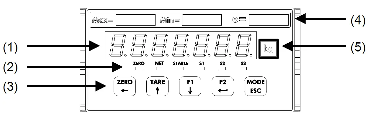
Front panel
| No. | Name | Description |
| (1) | Main display | Displays measured value or various settings. |
|
(2) | ZERO status | The LED is ON when the measured value is within 1/4 the minimum division. |
| NET status | The LED is ON when the net value is displayed. | |
| STABLE status | The LED is ON when the measured value is stable. | |
| S1 / S2 / S3 status | The LED is ON when the S1 / S2 / S3 status ON condition (FncF07 / 08 / 09) is met. | |
|
(3) | [ZERO/←] key | Zeros the gross value. Moves the flashing digit to the left when not in measurement mode. |
| [TARE/↑] key | Performs tare. Increases the flashing digit by one when not in measurement mode. | |
| [F1/↓] key | Performs the function set for the F1 key function (FncF05). Decreases the flashing digit by one when not in measurement mode. | |
|
[F2/ | Performs the function set for the F2 key function (FncF06). Updates the setting value entered when not in measurement mode. | |
| [MODE/ESC] key | Changes the operation mode. Cancels the setting value entered when not in measurement mode. | |
| (4) | Capacity label | Attach the included capacity label, if necessary. |
| (5) | Unit label | Attach the included unit label, if necessary. |
Rear panel
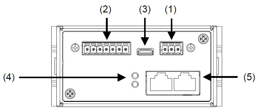
| No. | Name | Description |
| (1) | DC power input terminals | Terminals for connection of a DC24V power supply. |
| (2) | Load cell input terminals | Terminals for connection of load cells. |
| (3) | USB connector | Connector for connection with setting PC. (Type-C) |
| (4) | Field network status LEDs | Notifies field network status. |
| (5) | Field network connector | Connector for connection of PLC via field network. Dual ports can be used for daisy chain wiring (RJ-45). |
Accessories
Waterproof packing, Panel mount bracket x2, Capacity label, Unit label, Power connector, Load cell connector.
Mounting to control panel
Insert the waterproof packing around the Unit, and insert the Unit through the front of the panel. Insert the left and right mounting brackets into the case grooves and push until they reach the panel.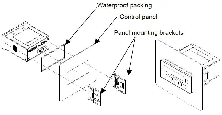
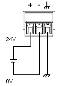
Connection to power supply and connection to load cell
Attach the accessory power connector and wire as shown in the figure below.
Applicable wire
| Item | Specifications |
| Wire size | 0.14 to 1.5 mm² (AWG 26 to 16) |
| Wire strip length | 7 mm |
| Tightening torque | 0.22 to 0.25 Nm |
In the case of the 4-wire connection type, attach the accessory load cell connector and wire as shown below. Change the load cell connection type (CALF17) in the calibration function to 0: 4-wire type (default value = 1: 6-wire type).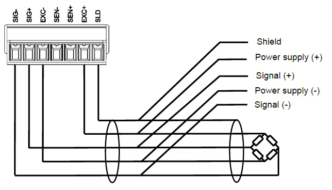
6-wire connection Set load cell connection type (CALF17) to 1: 6 wire type (Default). When you connect the load cells in parallel, use a summing box. Attach the accessory load cell connector and wire as shown below.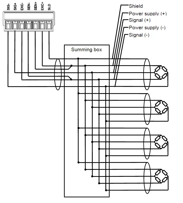
Calibration
Calibrate the AD-4411 to properly convert the signal from the load cell to a load value. Please prepare a calibration weight.
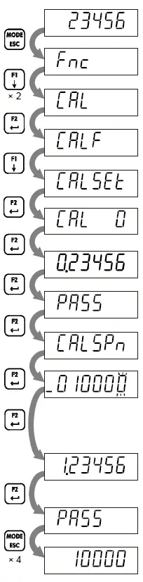
- After Power-On, press the [MODE/ESC] key more than 3s.
- Press the [F1/↓] key twice.
- Press the [F2/
 ] key.
 - Press the[F1/↓] key.
- Actual load calibration
- Press the [F2/ ] key.
- Press the [F2/ ] key.
- The current load cell input signal (mV/V) will be displayed. Press the [F2/ ] key to execute Zero calibration.
- If Zero calibration is successful, “PASS” will be displayed, and zero calibration will be completed.
- Press the [F2/ ] key.
- Press the [F2/ ] key.
- Set a calibration weight value by the following key operations.
- [ZERO/←] key: Moves the flashing digit to the left.
- [TARE/↑] key: Increases the flashing digit by one.
- [F1/↓] key: Decreases the flashing digit by one.
- [F2/ ] key: Confirm the setting value.
- The current load cell input signal (mV/V) will be displayed. Place the calibration weight or apply a load on the load cell. Press the [F2/ ] to execute Span calibration.
- If span calibration is successful, “PASS” will be displayed, and span calibration will be completed.
- Press the [MODE/ESC] key four times to return to the measurement mode.

Operation mode
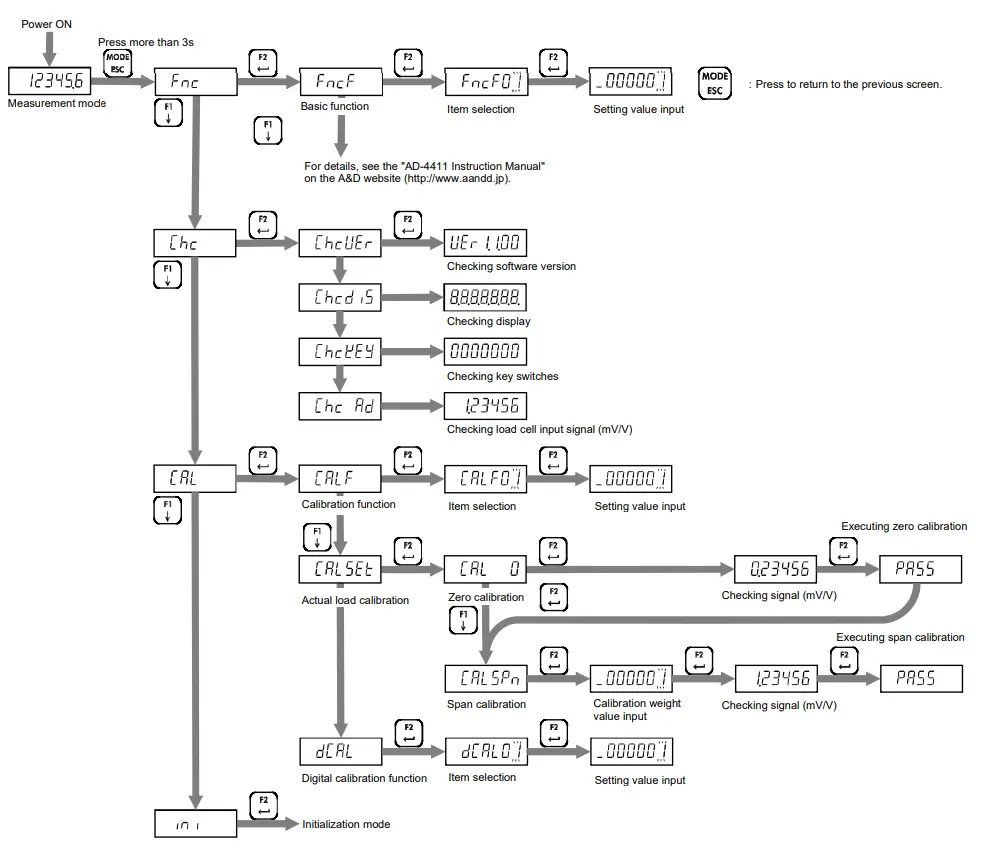
Function list
Calibration function list
| CALF | Setting item | Setting value | Default |
| 01 | Unit | 0: None / 1: g / 2: kg / 3: t | 2 |
| 02 | Decimal point position | 0: 0 (No decimal point) / 1: 0.0 / 2: 0.00 / 3: 0.000 / 4: 0.0000 / 5: 0.00000 | 0 |
| 03 | Minimum division d | 1: 1 d / 2: 2 d / 3: 5 d / 4: 10 d / 5: 20 d / 6: 50 d | 1 |
| 04 | Maximum capacity | 1 to 999999 | 999999 |
| 05 | Zero setting range | 0 to 100 % | 100 |
| 06 | Zero tracking time | 0.0 to 5.0 s | 0.0 |
| 07 | Zero tracking width | 0: Disable / 1: 0.5 d / 2: 1.0 d / 3: 1.5 d / 4: 2.0 d / 5: 2.5 d / 6: 3.0 d / 7: 3.5 d / 8: 4.0 d / 9: 4.5 d | 0 |
| 08 | Stability detection time | 0.0 to 9.9 s | 1.0 |
| 09 | Stability detection width | 0 to 100 d | 2 |
| 10 | Zero-setting when unstable | 0: Disable / 1: Enable | 1 |
| 11 | Taring when unstable | 0: Disable / 1: Enable | 1 |
| 12 | Taring when the gross is negative | 0: Disable / 1: Enable | 1 |
| 13 | Zero clear | 0: Disable / 1: Enable | 1 |
| 14 | Power-on zero | 0: Disable / 1: Enable | 0 |
| 15 | Condition of negative overload | 0: Gross < -(Maximum capacity + 8d) / 1: Gross < -19d | 0 |
| 16 | NTEP | 0: Disable / 1: Enable | 0 |
| 17 | Load cell connection type | 0: 4-wire type / 1: 6-wire type | 1 |
Digital calibration function list
| DCAL | Setting item | Setting value | Default |
| 01 | Load cell input signal at Zero Calibration | -7.00000 to 7.00000 mV/V | 0.00000 |
| 02 | Load cell input signal (at Span Calibration – at Zero Calibration) | 0.00001 to 7.00000 mV/V | 2.00000 |
| 03 | Weight value at Span Calibration | 1 to 999999 | 20000 |
Basic function list
| FncF | Setting item | Setting value | Default | |||
| 01 | Locking [ZERO/←] key | 0: Disable / 1: Enable | 0 | |||
| 02 | Locking [TARE/↑] key | 0: Disable / 1: Enable | 0 | |||
| 03 | Locking [F1/↓] key | 0: Disable / 1: Enable | 0 | |||
| 04 | Locking [F2/ ] key | 0: Disable / 1: Enable | 0 | |||
| 05 | Function of [F1/↓] key | 0: None / 1: Tare clear / 2: Zero clear / 3: Gross / net display selection 4: High-resolution display selection | 0 | |||
| 06 | Function of [F2/ ] key ] key | 0 | ||||
| 07 | Condition to turn S1 status ON | 0: None / 1: Hi / 2: OK / 3: Lo / 4: Zero setting error / 5: Taring error / 6: High resolution display | 0 | |||
| 08 | Condition to turn S2 status ON | 0 | ||||
| 09 | Condition to turn S3 status ON | 0 | ||||
| 10 | Digital filter cut-off frequency [Hz] | 0: 273.0 1: 120.0 2: 100.0 3: 84.0 4: 70.0 5: 68.0 6: 56.0 7: 48.0 8: 40.0 9: 34.0 10: 28.0 11: 24.0 | 12: 20.0 13: 17.0 14: 14.0 15: 12.0 16:10.0 17: 8.4 18: 7.0 19: 6.8 20: 5.6 21: 4.8 22: 4.0 23: 3.4 | 24: 2.8 25: 2.4 26: 2.0 27: 1.7 28: 1.4 29: 1.2 30: 1.0 31: 0.84 32: 0.70 33: 0.68 34: 0.56 35: 0.48 | 36: 0.40 37: 0.34 38: 0.28 39: 0.24 40: 0.20 41: 0.17 42: 0.14 43: 0.12 44: 0.10 45: 0.08 46: 0.07 | 30 |
| 11 | Upper limit value | -999999 to 999999 | 10 | |||
| 12 | Lower limit value | -999999 to 999999 | -10 | |||
| 13 | Comparison target for Upper limit value / Lower limit value | 1: Gross / 2: Net | 1 | |||
For functions other than those listed above, see the “AD-4411 Instruction Manual” on the A&D website (http://www.aandd.jp).
Specifications
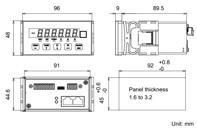
| Dimension | 96(W) x 48(H) x 98.5(D) mm | |
| Installation method | Panel mount | |
| Operating temperature and humidity range | -10°C to +40°C Less than 85%RH, non-condensing | |
| IP rating | (When the indicator is installed to the control panel) Front panel: IP65. Inside the panel: IP2X | |
| Power supply | DC24V -15% to +10%, 4.5W max. | |
| Load cell input | ||
| Excitation voltage | DC5V ±5% 90 mA Up to six 350 Ω load cells can be connected in parallel. 6-wire type with remote sensing | |
| Signal input range | -7.0 mV/V to +7.0 mV/V | |
| minimum input sensitivity | 0.15 μV/d or more (d=minimum division) | |
| Nonlinearity | 0.005% of F.S. max. | |
| Temperature coefficient | Zero drift: ±0.02 μV/°C typ. ±0.1 μV/°C max. Span drift: ±3 ppm/°C typ. ±15 ppm/°C max. | |
| Sampling rate | 1200 times / second | |
| Display | ||
| Main display | 7-digit LED (green) with a character height of 10 mm | |
| Status display | LED (red) x 6 | |
| Unit | Attach a label of g / kg / t | |
| Key switches | x 5 | |
| External interface | ||
| AD-4411-EIP | EtherNet/IP | |
| AD-4411-PRT | PROFINET | |
| AD-4411-ECT | EtherCAT | |
| USB | Type-C connector, USB 2.0 (Full-speed) | |
External dimension