SALUS Wired Thermostat
Introduction
The VS35 thermostat controls temperatures of individual heating zone in underfloor heating systems. Thermostat allows for significant savings thanks to the possibility of maximum reduction the set temperature. The full version of the manual in PDF format is available on the website www.salus-controls.eu
This product complies with the following EU Directives: Electromagnetic Compatibility 2014/30/EU, Low Voltage Directive 2014/35/EU and RoHS 2011/65/EU. Full information is available on the website www.saluslegal.com
Safety Information
Use in accordance with national and EU regulations. Use the device only as intended, keeping it in a dry condition. The product is for indoor use only. Installation must be carried out by a qualified person in accordance with national and EU regulations.
Terminals Description
Terminal | Description |
L, N | Power Supply 230 V AC |
NSB | Night SetBack (input 230 V AC) |
SL | Switched output (230 V AC) |
S1, S2 | External temperature sensor |
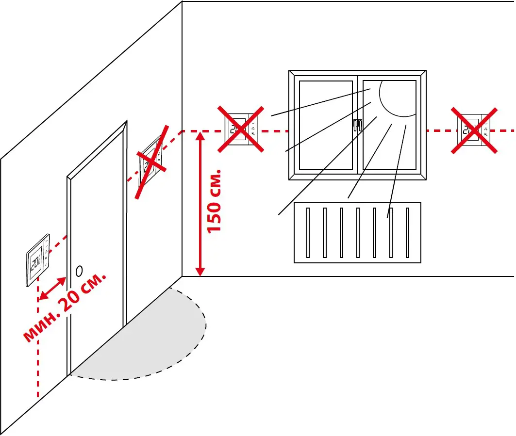
Proper Thermostat Placement
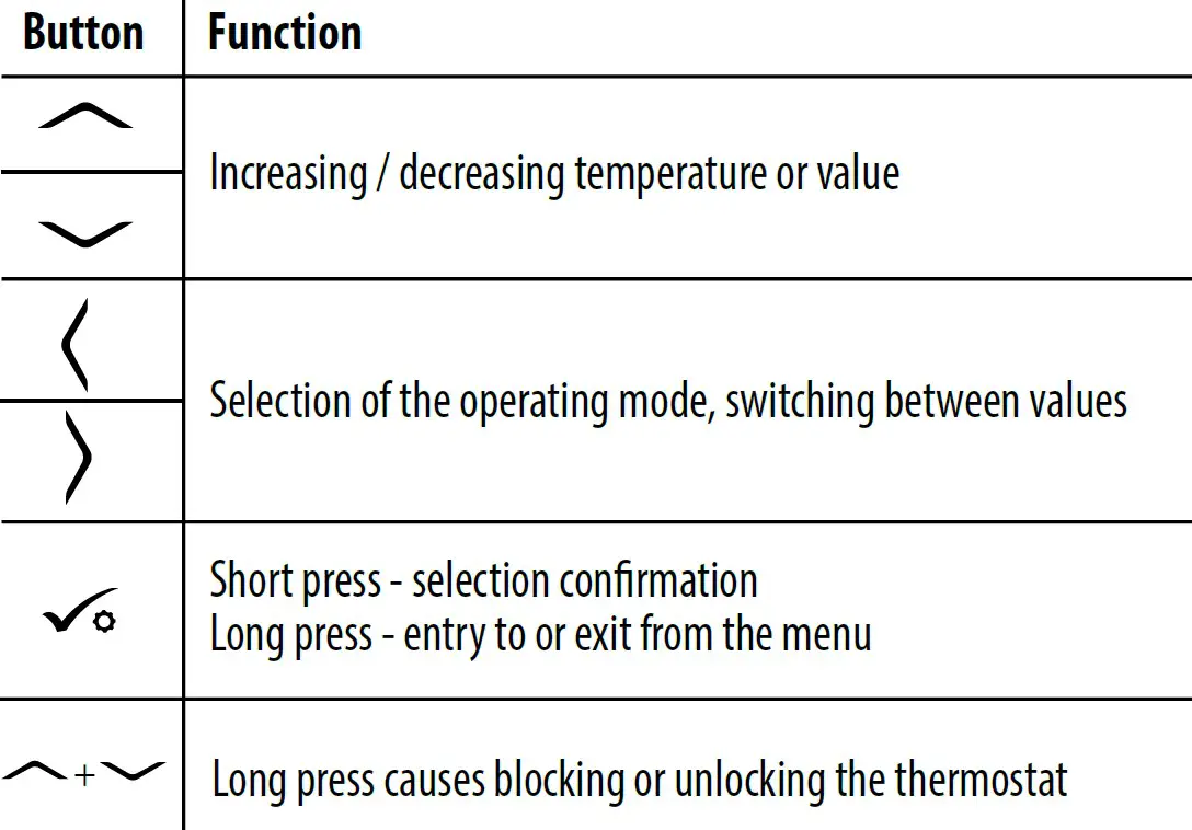
LCD Icon Description
![]()
- Current active mode
- Comfort mode
- Standard mode
- Economic mode
- Automatic mode
- Frost protection mode
- Temperature unit
- Manual mode / temp. override
- Current / set temperature
- Key lock
- Settings
- Additional temperature sensor
- Cooling
- Heating
Installation
The VS35 thermostat has been designed for flush mounting in a standard electrical box with a diameter of 60 mm.
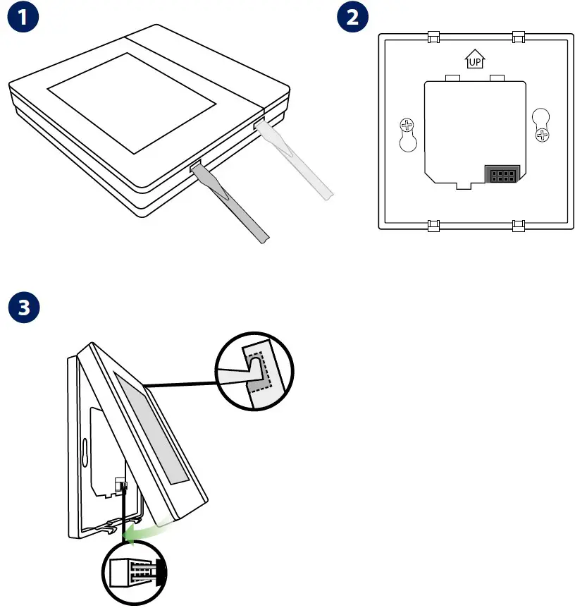
Note: Use the rear plate of the VS35 thermostat only with this model.
Wiring Diagrams
An additional temperatur Te sensor is optional. VS35 thermostat in connection with wiring centre.
In this diagram, the VS30 thermostat manages the NSB function, more details about NSB function can be found on the next page.
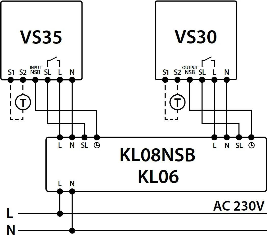
Note: In the KL06 wiring centre, the SL terminal is marked with an arrow icon.
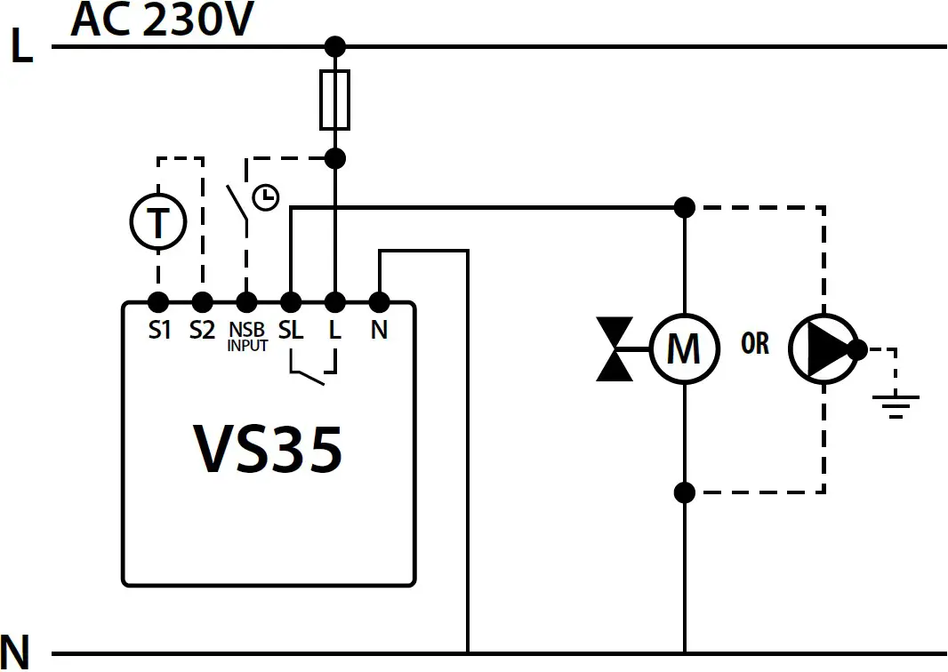
NSB function and an additional temperature sensor T is optional.
VS35 thermostat in connection with actuator or pump
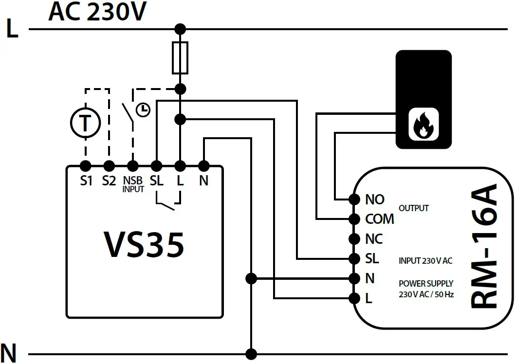
VS30 thermostat in connection with a boiler with a “NO” voltage free terminal through the RM-16A relay
Temperature Setting
Press any button to highlight the screen, then follow the steps below:
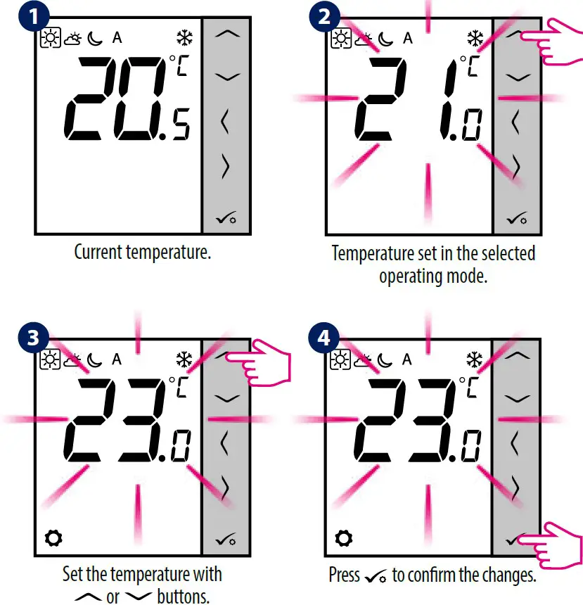
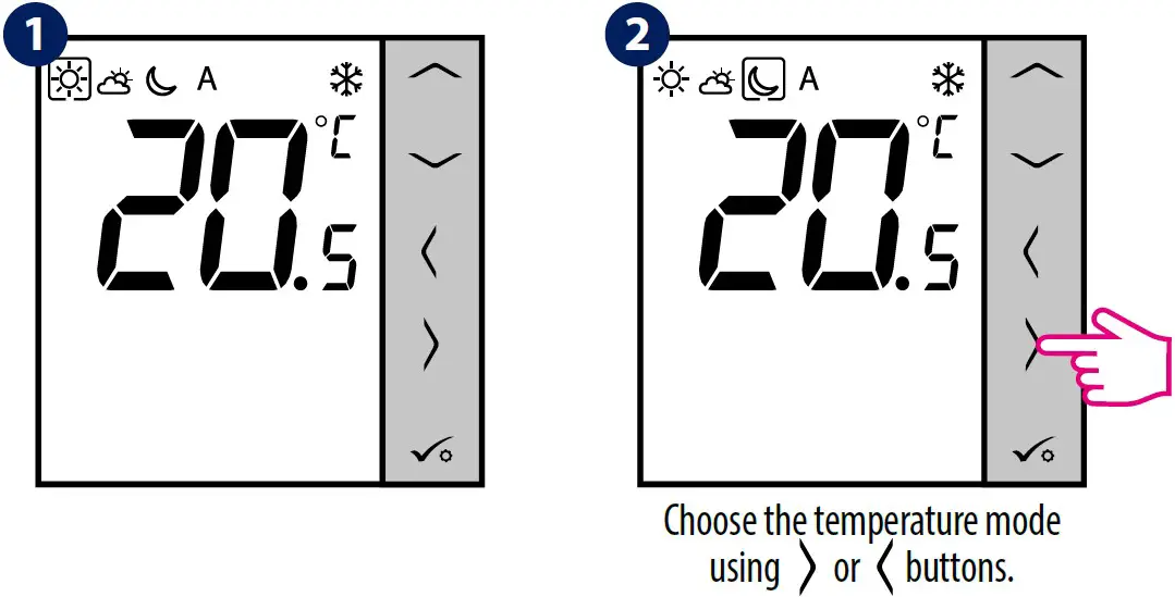
Manual Mode – Temperature Settings
There are 4 temperature levels available. In manual mode only one temperature level is active (icon in the frame indicates which mode is currently choosen). For each temperature levels you can set a different temperature.
- Comfort mode
- Standard mode
- Economic mode
- Frost protection mode. Usually used in a longer period of absence or during the holidays (available only in heating mode).
Press any button to highlight the screen, then follow the steps below:
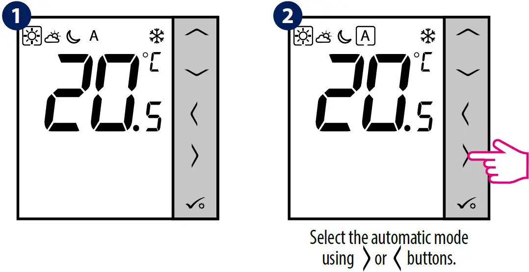
NSB Function – Automatic Mode
The NSB (Night SetBack) function can automatically change temperatures on VS35 daily thermostats via VS30 programmable thermostat connected to a wiring centre (or another external clock). NSB function switches between comfortable temperature and economic temperature.
To activate the automatic mode, select the A icon. On display together with the icon, the A controller indicates active temperature mode:
Press any button to highlight the screen, then follow the steps below:
Note: For the NSB function to work, it is necessary to connect the wirings properly. Connection diagrams can be found on the previous page.
Changing the HEATING / COOLING Mode
Press any button to highlight the screen, then follow the steps below:
Note: Heating / cooling mode can also be set using the service parameter d18.
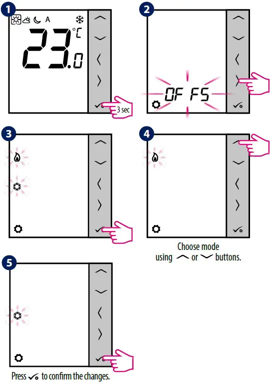
Offset Function (Temperature Calibration)
The VS35 thermostat allows you to adjust the displayed temperature ± 3.0°C. You can do it according to the following steps:
Press any button to highlight the screen, then follow the steps below:
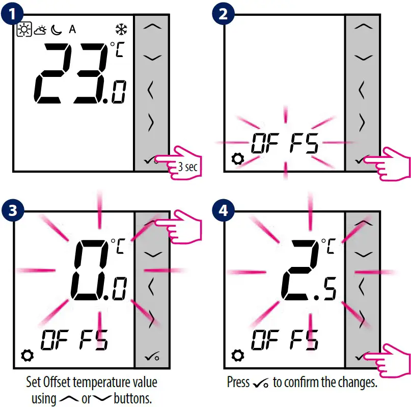
Note: You can also set the Offset temperature value using the service parameter d02.
Installer Settings
Press any button to highlight the screen, then follow the steps below:
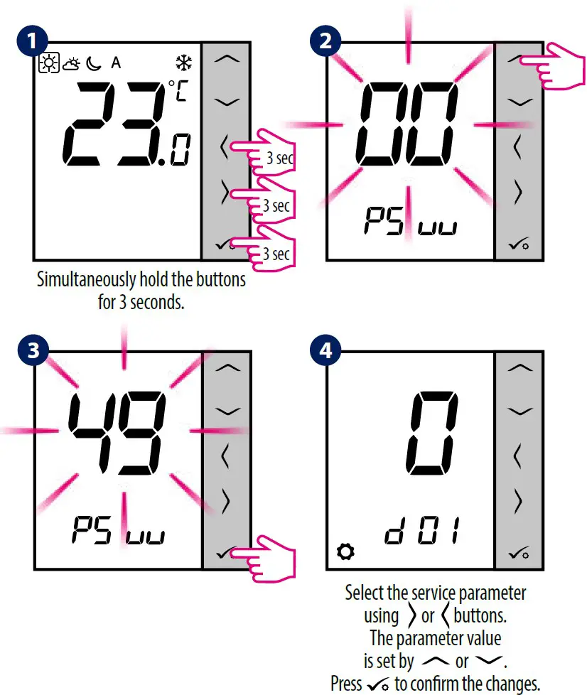
Note: To restore the thermostat’s factory settings, in step 2 set the PSuu to 47 code, and confirm the selection with the tick button.
dxx | Function | Value | Description | Default value |
d01 | Control method temperature | 0 | PWM algorithm | 0 |
1 | Span ±0.25°C | |||
2 | Span ±0.5°C | |||
d02 | Offset temperature | from -3.0°C to +3.0°C | If the thermostat indica- tes wrong temperature, you can correct it by ± 3.0°C | 0°C |
d03 | Using a floor temperature sensor (S1, S2) | 0 | No sensor | 0 |
| 1 | Sensor is connected | |||
| d04 | External sensor used for air or floor temperature measurement (Function is active, when d03=1) | 0 | Thermostat measures the temperature only on the external sensor | 0 |
1 | The sensor is used as a protection against overheating the floor | |||
d05 | Cooling mode control method | 1 | Span ±0.5°C | 2 |
2 | Span ±1.0°C | |||
d06 | Type of thermoelectric actuator | 0 | NO – normally open | 1 |
1 | NC – normally closed | |||
d07 | Valve protection | 0 | OFF | 1 |
| 1 | ON | |||
d08 | Frost protection temperature | 5-17°C | Frost protection / Holiday mode temperature | 5°C |
d12 | Heating temperature limit | 5-35°C | The maximum heating temperature that can be set by the user | 35°C |
d13 | Cooling temperature limit | 5-40°C | The minimum cooling temperature that can be set by the user | 5°C |
d14 | Maximum floor temperature (this function is active in heating mode when d04 = 1) | 6-45°C | In order to protect the floor from overheating, heating will be turned OFF, when the maximum temperature of the floor sensor will be reached | 27°C |
d15 | Minimum floor temperature (this function is active in heating mode when d04 = 1) | 6-45°C | In order to protect the floor, heating will be turned ON, when the minimum temperature of the floor sensor will be reached | 10°C |
| d16 | Lower floor temperature limit for cooling (this function is active when d04 = 1) | 6-45°C | In order to protect the floor, cooling will be turned OFF, when the minimum temperature will be reached | 6°C |
d18 | Operating mode HEATING / COOLING | 0 | Heating system | 0 |
| 1 | Cooling system |
Error Codes
Error code | Description |
Err02 | The maximum / minimum floor temperature has been exceeded |
Err03 | Temperature sensor is faulty |
Err04 | Temperature sensor is shorted |


