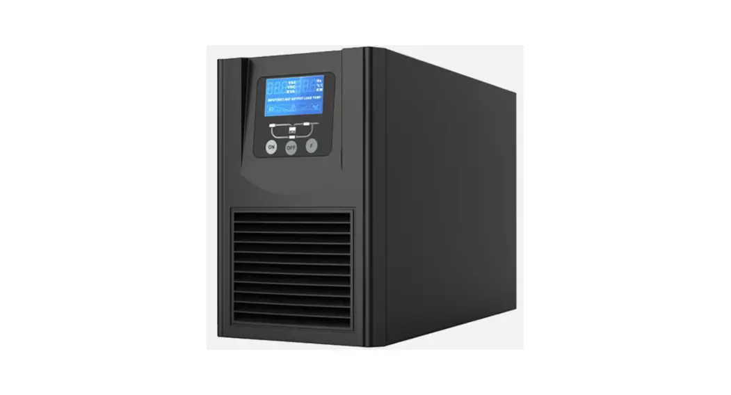
![]() 1-3kVA Pure Sinewave On-Line UPS
1-3kVA Pure Sinewave On-Line UPS
User Manual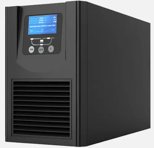 1-3KVA, 1:1 Phase
Pure Sinewave On-Line UPS
USER MANUAL
1-3kVA Pure Sinewave On-Line UPS
All rights reserved. The information in this document is subject to change without notice.
Publish statement
Thank you for purchasing the Enduro UPS series. This series UPS is an intelligent, single phase in single phase out, high frequency online UPS designed by our R&D team who is with years of designing experienceson UPS. With excellent electrical performance, perfect intelligent monitoring and network functions, smart appearance, complying with EMC and safety standards, The UPS meets the world’s advanced level.
Read this manual carefully before installation
This manual provides technical support to the operator of the equipment. The ENDURO range of UPS systems are intended for installation in a contaminant free environment with a temperature range between 0°C and 40°C.
Important Safety Warning
SAVE THESE INSTRUCTIONS. This manual contains important instruction that should be followed during installation and operation of the UPS and batteries.
Do not operate this unit before reading through all safety information and operating instructions carefully
The UPS contains its own power source (the battery). The power outlets may be energized even if the system is disconnected from the AC power source.
Dangerous voltage levels and high temperature components are present within the system. The UPS and its External Battery Modules should be opened exclusively by suitably trained and qualified personnel.
The batteries supplied within the system are valve regulated lead acid (VRLA) and contains small amounts of toxic materials. The batteries are certified as complying with UN2800 Special Provision A67 of the International Air Transport Association (IATA) Dangerous Goods Regulations.
Safety instructions in this manual act as a supplementary for the local safety instructions. PSS Distributors will not assume the liability that caused by disobeying safety instructions.
1-1 Transportation
Please transport the UPS system only in the original package to protect against shock and impact.
1-2 Preparation
Condensation may occur if the UPS system is moved directly from cold to warm environment. The UPS system must be absolutely dry before being installed. Please allow at least two hours for the UPS system to acclimate the environment. Do not install the UPS system near water or in moist environments. Do not install the UPS system where it would be exposed to direct sunlight or other heat sources. Do not block ventilation holes in the UPS housing.
1-3 Installation
- Do not connect appliances or devices with high inrush currents to the UPS system (e.g. laser printers, compressors, fridges and motors).
- Place cables in such a way that no one can step on or trip over them.
- Do not connect domestic appliances such as hair dryers to UPS output sockets.
- The UPS can be operated by any individuals with no previous experience.
- Connect the UPS system only to an earthed shockproof outlet which must be easily accessible and close to the UPS system.
- Use only Australian approved AC cables to connect the UPS system to the building supply and to connect the loads to the UPS system.
- When installing the equipment, it should ensure that the sum of the leakage current of the UPS and the connected devices does not exceed 3.5mA.
1-4 Operation
Do not disconnect the mains cable on the UPS system or the building wiring outlet (shockproof socket outlet) during operations since this would remove the protective earthing of the UPS system and of all connected loads. The UPS system features its own, internal current source (batteries). The UPS output sockets may be energized even if the UPS system is not connected to the building wiring outlet. To fully disconnect the UPS system, first press the OFF/Enter button to disconnect the mains. Isolate the UPS and check for hazardous voltage upstream and downstream during lockout-tagout operation. Prevent fluids or other foreign objects from entering the UPS system.
1-5 Maintenance
- The UPS system operates with hazardous voltages. Repairs and maintenance must be carried out by qualified UPS maintenance personnel.
- Caution – risk of electric shock. Even after the unit is disconnected from the mains (building wiring outlet), components inside the UPS system are still connected to the battery and electrically live and dangerous.
- Before carrying out any kind of service and/or maintenance, disconnect the batteries and verify that no current is present, and no hazardous voltage exists at within the system.
- Caution – risk of electric shock. The battery circuit is not isolated from the input voltage. Hazardous voltages may occur between the battery terminals and the ground. Before touching, please verify that no voltage is present!
- Batteries
- Only persons are adequately familiar with batteries and with the required precautionary measures may replace batteries and supervise operations. Unauthorized persons must be kept well away from the batteries.
- The battery supplied with the system contains small amounts of toxic materials.
- Use appropriate PPE when handling the batteries.
- If a battery case is damaged there is potential exposure to sulfuric acid and lead.
- When replacing batteries, replace with the same type, capacity and number of batteries or battery packs.
- Do not mix old and new batteries and ensure that the batteries have the same state of charge and internal resistance.
- Read the battery manufacturer’s Safety Data Sheet prior to replacement.
- Dispose in accordance with federal, state, or local regulations.
- Recycle wherever possible
- Maintenance
- The UPS should be regularly maintained (12 Months, 6 Months etc)
- Maintenance intervals are dependent on the operating environment and the application.
- PSS offers a wide range of cost-effective preventative maintenance solutions.
 | |||||
| Non Contract – ONE-OFF Service | X | X | X | X | |
| BASIC CONTRACT | X | X | X | ||
| COMPREHENSIVE CONTRACT | X | ||||
| COMPREHENSIVE PLUS | |||||
Installation and setup
NOTE: Before installation, please inspect the unit. Be sure that nothing inside the package has been damaged. Please keep the shipping cartons and packing materials in a safe place for future use.
2-1 Unpack checking
- When removing the UPS or EBM from the packaging:
- Do not lift the UPS from the front panel.
- Do not lean the UPS when moving it out from the packaging.
- The UPS is heavy. Removing it from the carton requires a minimum of two people.
- Check to see if the UPS is visibly damaged during the transportation, do not switch on the UPS if any damage found. Please contact the supplier right away.
- Verify that the following additional items are included with the UPS:
- User manual
- Software Suite CD
- USB cable
- Input AC Power cord
- base brackets kit (tower installation)
- Rack brackets (rack installation)
2-2 Real panel view
EN1000 – 1KVA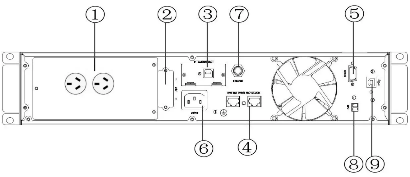
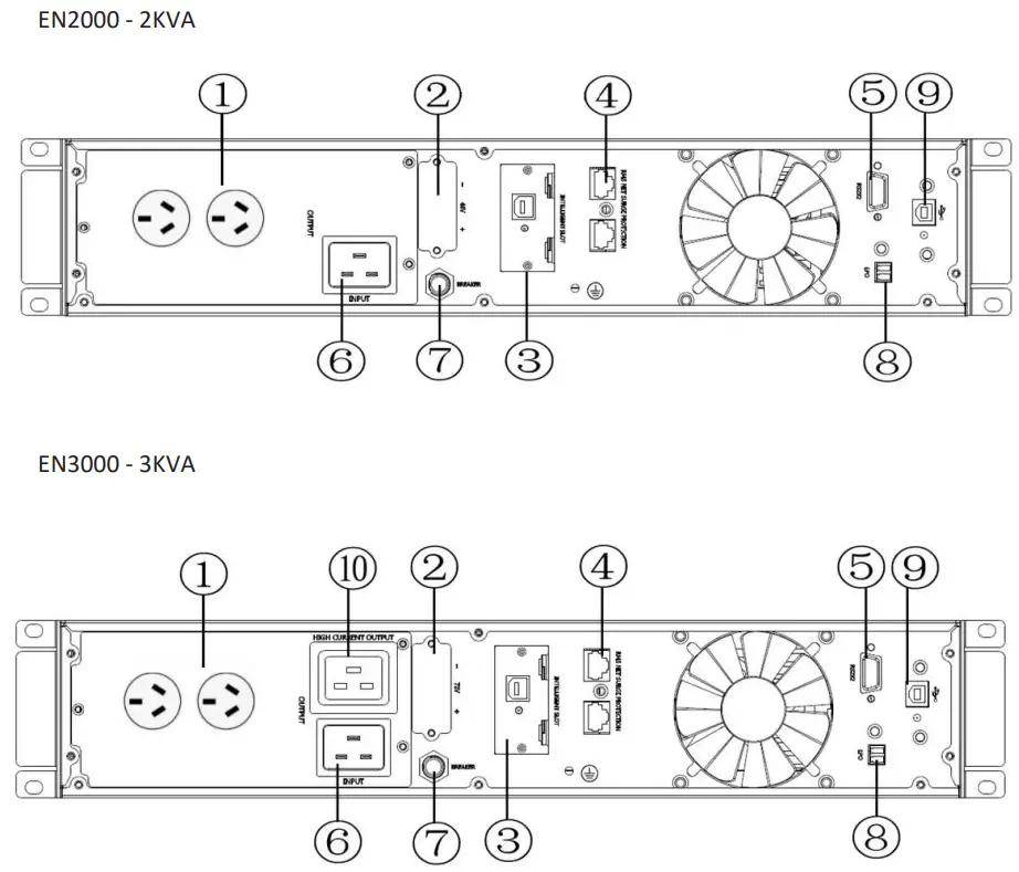
- Output receptacles (10A)
- External Battery Connector
- SNMP intelligent slot (optional SW006 SNMP card)
- Network /Fax/Modem Surge Protection
- RS-232 communication port
- AC input receptacle
- Input resettable fuse
- Connector for EPO (Emergency Power Off)
- USB communication port
- Output receptacle (16A)
2-3 Installing the UPS
Rackmount installation If installing optional external battery module(s) EBM(S), make sure to install the EBM(S) directly below the UPS module and the connector(s) are securely plugged in as detailed below.
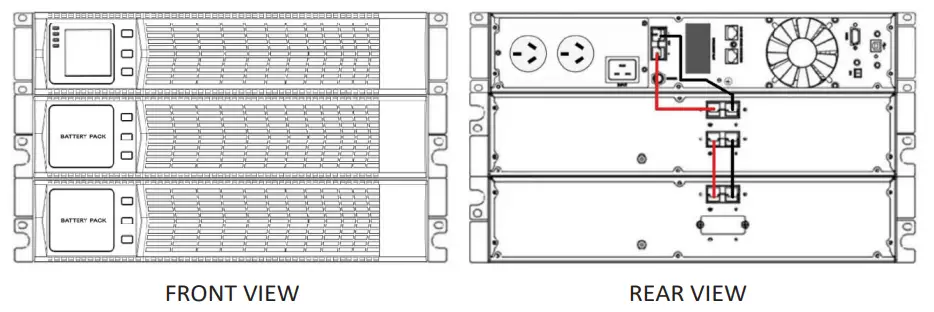 FRONT VIEW Optional adjustable rack mounting kits, part number RK1000 are available from your Enduro supplier.
 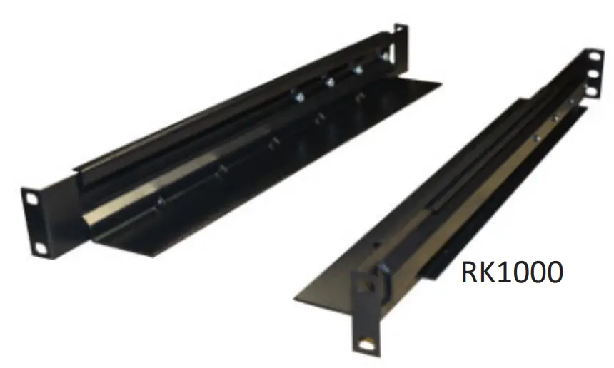 Tower Installation
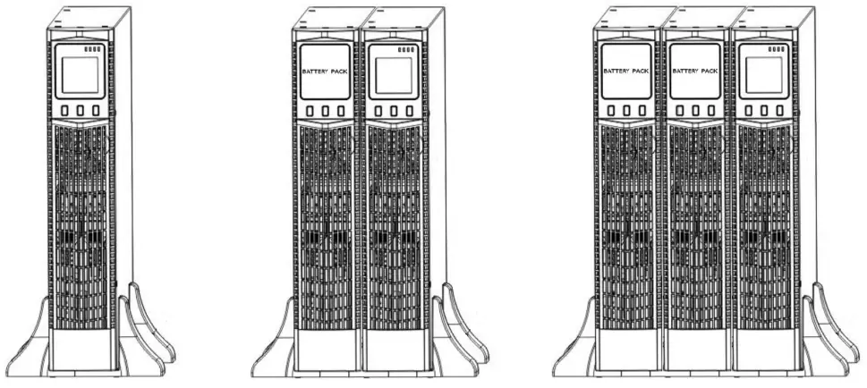 Connect the base brackets together for a single unit installation. Utilize the 1U base extender(s) to add
2-4 UPS startup and turn off
Startup operation
- Turn on the UPS ONLINE mode
NOTE Verify that the total equipment ratings do not exceed the UPS capacity to prevent an overload alarm.
a) Once mains power is plugged in, the UPS will startup in bypass mode (Bypass LED lit)
b) Press and hold the ON key for more than half a second to start the UPS.
c) The inverter will start, and the UPS will perform a self-test.
d) On completion of the self-test, the green LED will be lit, indicating the UPS is working ONLINE mode. - Turn on the UPS by DC without mains power
a) Ensure that the earth is connected via the AC supply cord.
b) Press and hold the ON key for more than half a second to start the UPS.
c) The inverter will start, and the UPS will perform a self-test.
d) On completion of the self-test, the amber battery LED will be lit, indicating the UPS is working ONLINE mode but drawing power from the batteries. An audible alarm will be heard. the self-test, the corresponding LED lights andthe UPS is working in battery mode.
Turn off operation
- Bypass the UPS
a) Press and hold the OFF key for more than half a second to turn off the inverter.
b) The Green ONLINE LED will extinguish, and the Bypass LED will be lit. - Turning off the UPS
c) Switch off the AC power supplying the UPS.
d) The UPS will shut down.
2-5 Configuring Battery Settings
- Set the UPS for the number of EBMs installed.
- To ensure maximum battery runtime, configure the UPS for the correct number of EBMs, refer to the table below for the appropriate setting.
- Refer to UPS Settings, section 3.3 screen number 4.
| All UPS and EBM Cabinets | Battery Capacity |
| UPS only (internal batteries) | 9Ah(default) |
| UPS+1EBM | 27Ah |
| UPS+2EBMs | 45Ah |
| UPS+3EBMs | 63Ah |
| UPS+4EBMs | 81Ah |
NOTE The UPS contains 1 battery string; each EBM contains 2 battery strings.
2-6 LCD control panel 2-7 Setup the UPS
Step 1: UPS input connection
- Using the AC power cord supplied, plug the UPS into the AC supply socket.
- Avoid the use of multiplugs and extension leads.
Step 2: UPS output connection
- Plug the load devices into the UPS.
Step 3: Communication connection
To allow for unattended UPS shutdown/start-up and status monitoring, connect the communication cable one end to the USB port and the other to the communication port of your PC. With the monitoring software installed, you can schedule UPS shutdown/start-up and monitor UPS status through PC.
The UPS is equipped with intelligent slot perfect for either SNMP or Relay card. When installing either SNMP (part number SW006) or Relay card (part number SW011), it will provide advanced communication and monitoring options.
Communication ports: Step 4: Turn on the UPS
Refer to section 2.4 Note: The battery charges fully during the first five hours of normal operation.
Step 5: Install software
For optimal computer system protection, install UPS monitoring software to fully configure UPS shutdown. You may insert provided CD into CD-ROM to install the monitoring software. The software can be download at http://www.megatec.com.tw/Download.htm
Operations
3-1 Button Operation
| Button | Function |
 | Turn on the UPS: Press and hold ON button for at least 2 seconds to turn on the UPS. Switch the UPS from bypass mode to ONLINE mode. UPS Setting Mode Choosing different value: When the UPS enters the setting mode, press this button to select the required value. |
 | Turn off the UPS: Press and hold button at least 2 seconds to turn off the UPS in battery mode. Switch the UPS from ONLINE mode to bypass mode. UPS Setting Mode Down key: Press button to display the next selection. |
 | Switch LCD message: Press button to change the LCD message for input voltage, input frequency, battery voltage, output voltage and output frequency etc. Rotate Key: Hold for 10 seconds to rotate the LCD screen. Mute the mains failure alarm: Hold button for at least 5 seconds to disable or enable the alarm system. UPS Setting Mode Up key: Press button to display previous selection. Switch to UPS self‐test mode: Press button for 2 seconds. |
 | Access UPS Setting Mode Press buttons simultaneously for 5 seconds. |
3-2 LCD display
Part one: Rack display
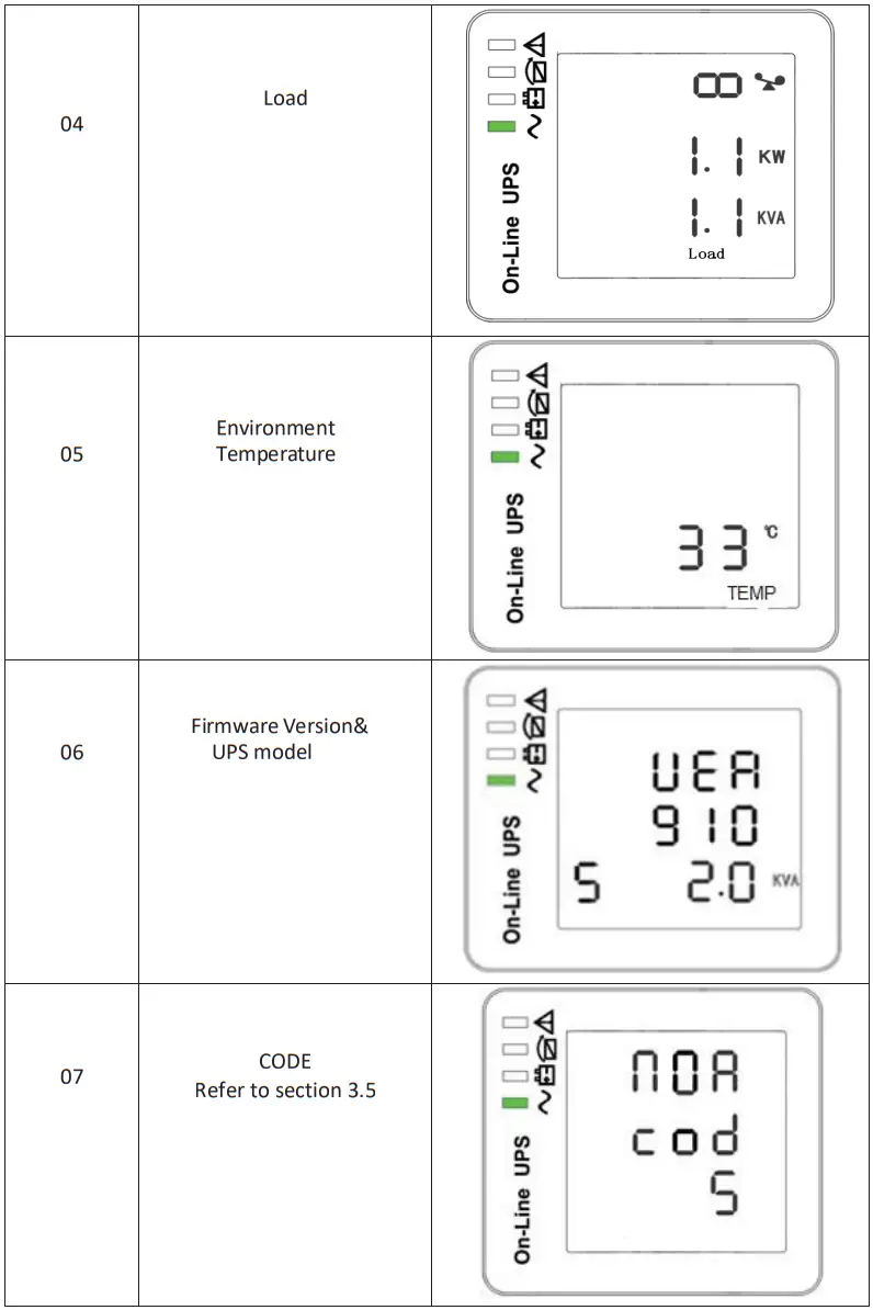
There are 8 interfaces available in the LCD display.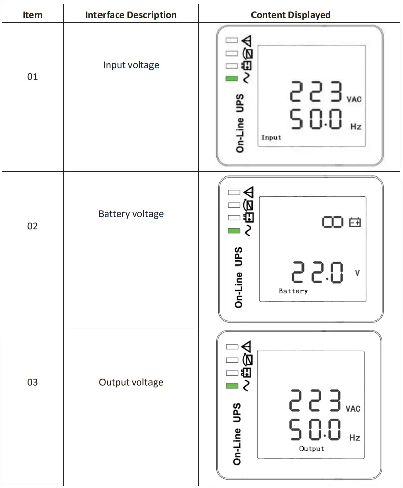
 3-3 UPS settings
The UPS should come preset and not require any adjustments. The setting function is controlled by the three buttons as detailed below. To access the setup, press the After the UPS turn ON, press buttons![]() +
+![]() for 5 seconds.
for 5 seconds.
| Item | Settings | Content display |
| 01 | MODE Press Enter button Press UP button ▲ to select the previous setting. Press DOWN ▼ button to select the next setting. | 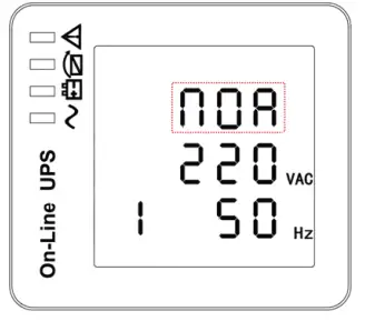 |
| 02 | OUTPUT VOLTAGE Press Enter button to change the setting (200V – 240V). Press UP button ▲ to select the previous setting. Press DOWN ▼ button to select the next setting. | 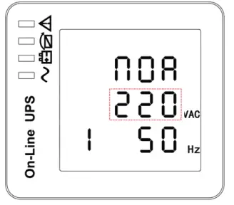 |
| 03 | FREQUENCY Press Enter button Press UP button ▲ to select the previous setting. Press DOWN ▼ button to select the next setting. | 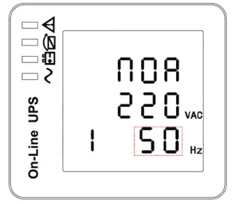 |
| 04 | BATTERY CAPACITY Press Enter button Default is 9Ah refer to section 2.5. Press UP button ▲ to select the previous setting. Press DOWN ▼ button to select the next setting. | 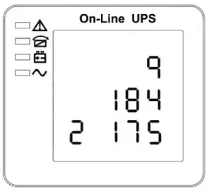 |
| 05 | LOW VOLTAGE ALARM Press Enter button Default setting: 185V / Cell Press UP button ▲ to select the previous setting. Press DOWN ▼ button to select the next setting. | |
| 06 | EOD Press Enter button Default setting: 185V / Cell Press UP button ▲ to select the previous setting. Press DOWN button ▼ to select theprevious setting. | |
| 07 | Bypass Voltage Upper limit Press Enter button Press UP button ▲ to selectthe previous setting. Press DOWN button ▼ to select the previous setting. |  |
| 08 | Bypass Voltage Lower limit Press Enter button Press UP button▲to select the previous setting. Press DOWN button▼to select the previous setting. | 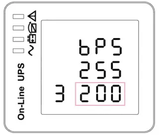 |
3-4 Operating Mode Description
| Mode | Description | Indicator |
| Line Mode | • The green LED is on. o Input AC mains is within limits, the UPS will function in ONLINE mode. | 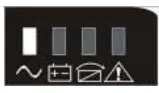 |
| Battery Mode | • The battery amber LED is on. o The alarm beeps once every 4 seconds. o Input AC mains is out of limits. • The battery amber LED flashes. o The battery voltage has reached the limit setin section 3.3 (05) • UPS power off o The battery voltage has reached the limit set in section 3.3 (06) • UPS will auto‐restart when the mains recover. |  |
| Bypass Mode | • The bypass amber LED is on. • The UPS is in bypass. | 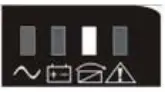 |
| ECO Mode | • The bypass amber LED is on. • When ECO enabled and the AC mains is in range, the UPS will work on ECO Mode. • If the AC mains is out of range the UPS will transfer to ONLINE mode. | |
| Fault Mode | • The warning red LED is on and the alarm beeps.The UPS is in fault mode. • NOTE: please refer to alarm or fault reference code. |  |
3-5 Operational Status and Mode(s)
| item | Content Displayed |
| 2 | Standby Mode |
| 3 | No Output |
| 4 | Bypass Mode |
| 5 | Utility Mode |
| 6 | Battery Mode |
| 7 | Battery Self‐diagnostics |
| 8 | Inverter is starting up |
| 9 | ECO Mode |
| 10 | EPO Mode |
| 11 | Maintenance Bypass Mode |
| 12 | Fault Mode |
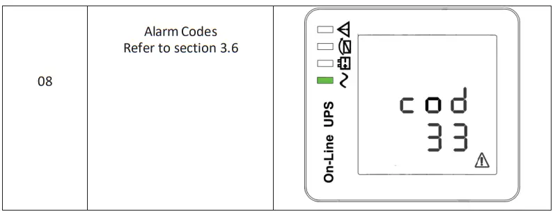
3-6 Alarm or Fault reference codes
| Event log | UPS Alarm Warning | Buzzer | LED |
| 2 | Inverter fault (Including Inverter bridg is shorted) | Beep continuously | Fault LED lit |
| 9 | Fan fault | Beep continuously | Fault LED lit |
| 12 | Self‐test fault | Beep continuously | Fault LED lit |
| 13 | Battery Charger fault | Beep continuously | Fault LED lit |
| 15 | DC Bus over voltage | Beep continuously | Fault LED lit |
| 16 | DC Bus below voltage | Beep continuously | Fault LED lit |
| 17 | DC bus unbalance | Beep continuously | Fault LED lit |
| 18 | Soft start failed | Beep continuously | Fault LED lit |
| 19 | UPS Inside Over Temperature | Twice per second | Fault LED lit |
| 20 | Heat sink Over Temperature | Twice per second | Fault LED lit |
| 26 | Battery over voltage | Once per second | Fault LED blinking |
| 29 | Output Short‐circuit | Once per second | Fault LED blinking |
| 30 | Input current limit | Once per second | Fault LED blinking |
| 31 | Bypass over current | Once per second | BPS LED blinking |
| 32 | Overload | Once per second | INV or BPS LED blinking |
| 33 | No battery | Once per second | Battery LED blinking |
| 34 | Battery under voltage | Once per second | Battery LED blinking |
| 35 | Battery low pre‐warning | Once per second | Battery LED blinking |
| 36 | Overload time out | Once per 2 seconds | Fault LED blinking |
| 37 | DC component over limit. | Once per 2 seconds | INV LED blinking |
| 39 | Main’s volt. Abnormal | Once per 2 seconds | Battery LED lit |
| 40 | Mains freq. abnormal | Once per 2 seconds | Battery LED lit |
| 41 | Bypass Not Available | BPS LED blinking |
Troubleshooting
If the UPS system does not operate correctly, please solve the problem by using the table below.
| Symptom | Possible cause | Remedy |
| No indication and alarm even though the mains is normal. | The AC input power isnot connected well. | Check if input power cord firmly connected to the mains. |
| The AC input is connected to the UPS output. | Plug AC input power cordto AC input correctly. | |
| Alarm code is shown as”33″and battery led blinking. | The external or internal batten/ is incorrectly connected. | Check if all batteries are connected well. |
| Alarm code is shown as “26”and battery led blinking. | voltage Is too Battery high or the charger is fault. | Contact your dealer. |
| Alarm code is shown as “34”and battery led blinking | Battery voltage is toolow or the charger is fault. | Contact your dealer. |
| Alarm code is shown as “3 2″and INV or BYPASS led blinking. | UPS is overload | Remove excess loads fromUPS output. |
| Alarm code is shown as ” 29″and FAULT led light. | The UPS shut down automatically because short circuit occurs on the UPS output. | Check output wiring and if connected devices are in short circuit status. |
| Alarm code is shown as “9”and FAULT led light. | Fan fault. | Contact your dealer. |
| Alarm code is shown as 01,02, 15,16,17,18″ | A UPS internal faulthas occurred. | Contact your dealer. |
| Battery backup time is shorterthan nominal value | Batteries are not fully charged | Charge the batteries for atleast 5 hours and then check capacity. If the problem still persists, consult with your dealer. |
| Batteries defect | Contact your dealer to replace the battery. |
Storage and Maintenance
Operation
The UPS system contains no user‐serviceable parts. If the battery service life (3~5 years at 25°C mbient temperature) has been exceeded, the batteries must be replaced. In this case, please contact your dealer.
Storage
Before storing, charge the UPS 5 hours. Store the UPS covered and upright in a cool, dry location. During storage, recharge the battery in accordance with the following table:
| Storage Temperature | Recharge Frequency | Charging Duration |
| ‐25°C ‐ 40°C | Every 3 months | 1‐2 hours |
| 40°C ‐ 45°C | Every 2 months | 1‐2 hours |

- Loosen the 2 torque screws (on each side of the card).
- Carefully insert the SNMP / Relay card into the slot and lock the screws
SW006 SNMP
- Net Agent is a software tool to remotely monitor and manage the UPS.
- The software can be download at http://www.megatec.com.tw/Download.htm
SW011 Relay Card
| 1 | Common | ||
| 2 | UPS Active | Open when UPS Active | 2 & 1 open |
| 3 | Mains Fail | Open when Mains Fails | 3 & 1 open |
| 4 | Close when Mains Fails | 4 & 1 close | |
| 5 | Battery Low | Open when Battery Low | 7 & 1 open |
| 6 | Close when Battery Low | 8 & 1 close | |
| 7 | General Alarm | Open when UPS Alarm | 7 & 1 open |
| 8 | Close when UPS Alarm | 8 & 1 close | |
| 9 | Bypass Active | Open when Bypass Active | 9 & 1 open |
| 10 | Close when Bypass Active | 10 & 1 close | |
| 11 | UPS Fault | Open when UPS Fault | 11 & 1 open |
| 12 | Close when UPS Fault | 12 & 1 close | |
Contacts & Links
7-1 Warranty Registration
Please register your warranty with the serial number provided on the below link.
http://www.pssdistributors.com.au/ups‐warranty‐registration/
7-2 PSS Repair/RMA Form
https://pssdistributors.com.au/repair‐rma/
7-3 Service Enquiries
Email: [email protected]
Contact: 1300 882 447
Specification
| Model | EN 1000 | EN 2000 | EN 3000 |
| Capacity | 1kVA/900W | 2kVA/1800W | 3kVAl2700W |
| Input | |||
| Voltage range | 230V +/- 20% | ||
| Frequency range | 45Hz – 65Hz | ||
| Phase | Single phase | ||
| Power factor | .?- 0.98 | ||
| Breaker | 6A | 10A | 15A |
| Input socket | IEC C14 10A | IEC C14 10A | IEC C20 16A |
| Output | |||
| Voltage range | 230VAC+/-2% | ||
| Frequency ( battery mode) | 50Hz +/- 0.1Hz | ||
| Power factor | 0.9 | ||
| Current crest ratio | 3:01 | ||
| THD | c3%(linear Load); -05% (non-linear oad) | ||
| Waveform | Pure Sinewave | ||
| Output sockets | 2x AU 3 Pin sockets ( 1 critical I 1 non-critical) | 3x AU 3 Pin sockets ( 2 critical / 1 non-critical) | 3x AU 3 Pin sockets ( 2 critical! 1 non-critical) |
| Efficiency | ?.. 89% normal mode, up to 97% ECO mode | ||
| Overload capacity | 30s at 100-150%: 300ms at >150% | ||
| Battery | |||
| Type | Seated lead acid, maintenance free | ||
| Configuration (standard run) | 3x 12V / 9Ah | 6x 12V /9Ah | 6x 12V / 9Ah |
| Rated battery voltage | 36V | 72V | 72V |
| Charge current (Max) | 12A | ||
| Recharge time to 90% | 5 Hrs | ||
| Charge mode | Intelligent 3-stage charging | ||
| Comma & Management | |||
| Software | Windows 95198/NT/2000/XPNistaf7, Windows Server 2003/2008 Linux Deblan, Redhat, Fedora, Suss, Ubuntu, Cent0S. Novell. Mac, FreeBSD | ||
| Ports | USB and RS-232 standard | ||
| Optional | SNMP & relay (trigger voltage free contacts) | ||
| LED/LCO display | Load, battery, input, output, operating | ||
| Audible alarm | Battery mode, low battery, overload, fault | ||
| Protection | |||
| Surge protection | 2200 Joules/ 60,000 Amps | ||
| Input protection | Compliance with IEEE 587 | ||
| Short circuit | Resettable circuit breaker | ||
| EPO | Shuts down UPS immediately | ||
| EMC | EN50091-2, C Tick/RCM | ||
| Network | RJ45, fulltime network protection | ||
| Characteristics | |||
| Temperature | 0-40 °C | ||
| Humidity | 0 – 95% (non-condensing) | ||
| Noise level | <50dB at 1m | ||
| Dimensions (WxDxH) /weight | 440x430x86.5 (2RUy15.1kg | 440x600x86.5mm (2RU)126.3kg | 440x600x86.5mm (2RU)/26.8kg |
| Shipping dimensions (WxDxli)/weight | 560x560x210mm/17.9kg | 560x730x210mrs129.6kg | 560x730x210mm129.9kg |
| EBM dimensions (WxOxH) 1 weight | 440x430x86.5mm(2RU)120kg | 440x710x86.5mm(2RU)/33kg | 440x710x86.5mm(2RU)133kg |
| EOM shipping dimensions(VhdixH)fweigN | 560x560x210mm124.1kg | 560440x210mm./42.6kg | 560x810x210mm142.6kg |
![]() www.pssdistributors.com.au
www.pssdistributors.com.au
Email: [email protected]
Phone: 1300 882 447


