
AKO D14212 Thermostat Electronic Controller Instruction

Configurable electronic thermostats with 2 relays and up to 2 probes
The two probe inputs can be interrelated with the two relay outputs for the thermometer, thermostat and the timing functions in cold and heat applications.
CONFIGURATION allows that some parameters are ADJUSTABLE or not by the USER so that he or she has the exclusive information and adjustment that the device’s use requires. The functions of the front part keys as well as the display of temperatures can be modified, while the configuration with a password can be blocked.
Warnings
The use of the unit different to the manufacturer’s instructions voids the safety qualification. To ensure correct operation of the apparatus, only NTC type probes supplied by AKO should be used. Between -40 ºC and +20 ºC, when the probe is extended up to 1.000m with
minimum 0,5mm cable, deviation will be less than 0.25 ºC (probe extension cable ref. AKO-15586)
Versions and references
| MODEL | AKO-14722 | AKO-14723 | AKO-15223 |
| FASTENING UNIT | Panel mounting | Panel mounting | DIN raíl |
| POWER SUPPLY 50/60 Hz | 12 V ~_ ± 20% | 230 V~ ±10% | 230 V~ ±10% |
Installation
The controller must be installed in a place protected from vibrations, water and corrosive gases, and where the ambient temperature does not surpass the values specified in the technical data.
In order for the panel mounting units to be suitable having IP65 protection, the gasket should be installed properly between the apparatus and the perimeter of the panel cut-out where it is to be fitted. In order to give a correct reading, the probe has to be installed in a max. place without heat influences other than the temperature that is 18 mm to be measured or controlled.
Fastening units for panel mounting
To fix the unit, place the fasteners 1 over the sliders 2 as shown in the figure. Move the fasteners in the direction of the arrow. By pressing tab 3 the fasteners may be moved in the opposite direction of the arrow.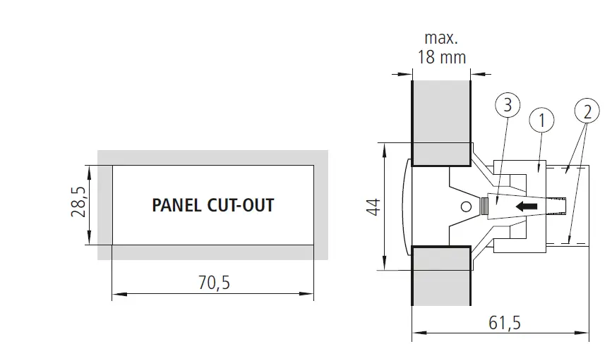
Fastening units for DIN rail mounting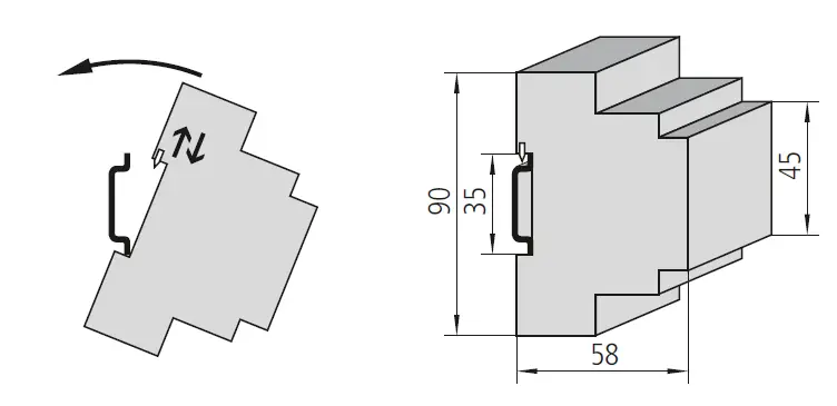
Connection
See diagram in the unit rating plate. The probe and its lead shoud NEVER be installed in ducting along with power, control or power supply wiring. The power supply circuit should be connected with a minimum 2A, 230V, switch located close to the unit. 2 2 The cables should be of the type H05VV-F 2×0,5mm or H05V-K 1×0,5mm . Section of connecting wires for relays contacts must be between 1mm2 and 2,5mm
Front panel functions
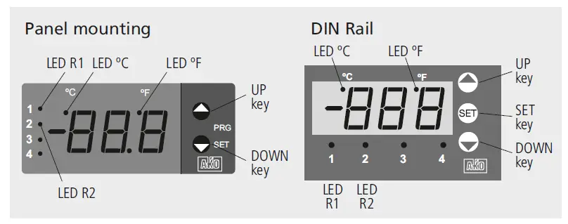
![]() N UP key: By pressing this key, the temperature in probe 2 is displayed. By pressing it during 5 seconds, the R2 SET POINT is displayed. In programming, it increases the value being displayed. By default, the configuration of this key is factory-set for the preceding actions. However, it can be configured according to the options of parameters 42,
N UP key: By pressing this key, the temperature in probe 2 is displayed. By pressing it during 5 seconds, the R2 SET POINT is displayed. In programming, it increases the value being displayed. By default, the configuration of this key is factory-set for the preceding actions. However, it can be configured according to the options of parameters 42,
- DOWN key:
 By pressing this key during 5 seconds, the R1 SET POINT is displayed.
 - In programming, it decreases the value being displayed.
- By default, the configuration of this key is factory-set for the preceding functions. However, it can be configured according to the options of parameters 44, 45.
UP + DOWN keys (panel mounting) or SET key (DIN rail) - Pressing these keys during 10 seconds accesses to the configuration of the controller parameters.
- Pressing these keys once accesses to the adjustment of the user’s parameters.
- By default, the configuration of these keys is factory-set for the preceding function, however, they can be configured according to the options of parameter 46.
LEDs - ºC: Permanent: Temperature display in ºC. Flashing, parameters programming phase.
- ºF: Temperature display in ºF.
- R1/R2: Relay R1/R2 activated.
Configuration and adjustment - It should only be programmed or modified by personnel who are fully conversant with the operation and possibilities of the equipment.
Level 1, Parameters - Press the CONFIGURE OR ADJUST keys for 10 seconds. The LED “ºC” will be flashing to indicate programming phase and the first parameter “01” will appear on the
- display. Pressing the
 key accesses the next parameter and the Q key will produce a return to the previous one.
 - Pressing DISPLAY VALUE key in the last display EP the controller will return to the current temperature display status and the LED “ºC” will stop flashing.
Level 2 Values - In order to display the current value of any parameter, select the desired parameter and press the DISPLAY VALUE keys. Once it is displayed, it can be modified by
- pressing the
 keys.
keys. - Pressing the ACCEPT THE NEW keys sets the new value. When this operation is performed, the programming returns to Level 1 (parameters).
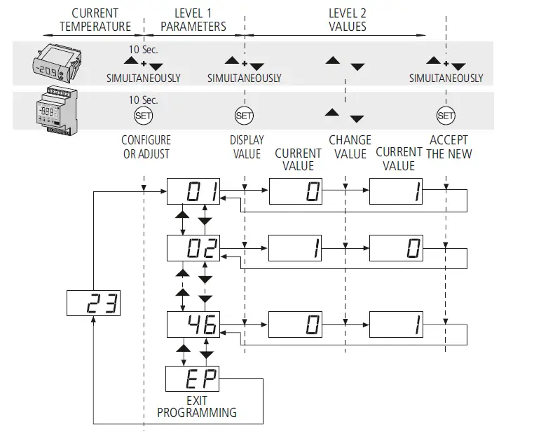
ADJUSTMENT: Pressing once the CONFIGURE OR ADJUST keys accesses the user’s parameters adjustment. The proceeding is the same as for the configuration and access is only possible to the parameters defined as adjustable by the user in the configuration. In order to access the parameters the parameter 39 parameter should be configured. REMARK: If no key is pressed for 25 seconds in any of the previous steps, the controller will automatically return to the current temperature display status without modifying any of the parameters values.
REMARK: When the time parameters are modified, the new values are applied once the current cycle is completed. In order for it to have an immediate effect, switch the controller off and then on again.
Description of parameters and messages
| Level 1 | |||||
| PARAMETERS | |||||
| Description | Values | Min. | Def. | Max. | |
| 01 | Temperature display mode: 0 =Whole in ºC 1 = One decimal in ºC 2 =Whole in ºF 3 = One decimal in ºF | 0 | 1 | 3 | |
| 02 | Probe 1, Enable? (S1) 0=No, 1=Yes | 0 | 1 | 1 | |
| 03 | Probe 1 calibration (S1) | (ºC / ºF) | -20.0 | 0.0 | 20.0 |
| 04 | Parameter 03 adjustable by the user? 0=No, 1=Yes | 0 | 0 | 1 | |
| 05 | Probe 2, Enable? (S2) 0=No, 1=Yes | 0 | 1 | 1 | |
| 06 | Probe 2 calibration (S2) | (ºC / ºF) | -20.0 | 0.0 | 20.0 |
| 07 | Parameter 06 adjustable by the user? 0=No, 1=Yes | 0 | 0 | 1 | |
| 08 | Thermostat relay R1, Enable? 0=No, 1=Yes | 0 | 1 | 1 | |
| 09 | Thermostat relay R1, Probe selection 0=S1-S2, 1=S1, 2=S2 | 0 | 1 | 2 | |
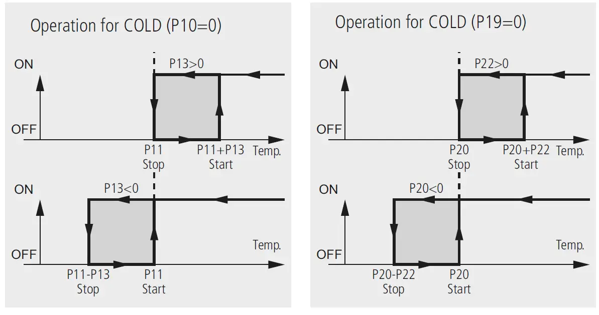
| 10 | Thermostat relay R1, Operation type 0=Cold, 1=Heat | 0 | 1 | 1 | |
| 11 | Thermostat relay R1, Set Point | (ºC / ºF) | -50.0 | 0.0 | 99.0 |
| 12 | Parameter 11 adjustable by the user? 0=No, 1=Yes | 0 | 1 | 1 | |
| 13 | Thermostat relay R1, Differential (Hysteresis) | (ºC / ºF) | -90.0 | 1.0 | 90.0 |
| 14 | Parameter 13 adjustable by the user? 0=No, 1=Yes | 0 | 1 | 1 | |
| 15 | Thermostat relay R1, connection delay or protection | (min) | 0 | 0 | 120 |
| 16 | Parameter 15 adjustable by the user? 0=No, 1=Yes | 0 | 1 | 1 | |
| 17 | Thermostat relay R2, Enable? 0=No, 1=Yes | 0 | 1 | 1 | |
| 18 | Thermostat relay R2, Probe selection 0=S1-S2, 1=S1, 2=S2 | 0 | 1 | 2 | |
| 19 | Thermostat relay R2, Operation type 0=Cold, 1=Heat | 0 | 1 | 1 | |
| 20 | Thermostat relay R2, Set Point | (ºC / ºF) | -50.0 | 0.0 | 99.0 |
| 21 | Parameter 20 adjustable by the user? 0=No, 1=Yes | 0 | 1 | 1 | |
| 22 | Thermostat relay R1, Differential (Hysteresis) | (ºC / ºF) | -90.0 | 1.0 | 90.0 |
| 23 | Parameter 22 adjustable by the user? 0=No, 1=Yes | 0 | 1 | 1 | |
| 24 | Thermostat relay R2, connection delay or protection | (min.) | 0 | 0 | 120 |
| 25 | Parameter 24 adjustable by the user? 0=No, 1=Yes | 0 | 1 | 1 | |
| 26 | Timing relay R1, Enable? 0=No, 1=Yes | 0 | 0 | 1 | |
| 27 | Timing relay R1, Elapsed time between starts | (h.) | 0 | 0 | 120 |
| 28 | Parameter 27 adjustable by the user? 0=No, 1=Yes | 0 | 1 | 1 | |
| 29 | Timing relay R1, Duration | (min.) | 0 | 0 | 120 |
| 30 | Parameter 29 adjustable by the user? 0=No, 1=Yes | 0 | 1 | 1 | |
| 31 | Timing relay R1, Relay status during P29 0=OFF, 1=ON | 0 | 0 | 1 | |
| 32 | Timing relay R2, Enable? 0=No, 1=Yes | 0 | 0 | 1 | |
| 33 | Timing relay R2, Elapsed time between starts | (h.) | 0 | 0 | 120 |
| 34 | Parameter 33 adjustable by the user? 0=No, 1=Yes | 0 | 1 | 1 | |
| 35 | Timing relay R2, Duration | (min.) | 0 | 0 | 120 |
| 36 | Parameter 35 adjustable by the user? 0=No, 1=Yes | 0 | 1 | 1 | |
| 37 | Timing relay R1, Relay status during P35 0=OFF, 1=ON | 0 | 0 | 1 | |
| 38 | Parameters transfer 0=disabled,1=send, 2=receive | 0 | 0 | 2 | |
| 39 | Password to modify the configuration | 0 | 0 | 126 | |
| 40 | Program version (information) | ||||
| 41 | Display without pressing any key | 1 | 1 | 4 | |
| 42 | Function by pressing UP key | 0 | 2 | 7 | |
| 43 | Function by pressing UP key during 5” | 0 | 4 | 7 | |
| 44 | Function by pressing DOWN key | 0 | 0 | 7 | |
| 45 | Function by pressing DOWN key during 5” | 0 | 3 | 7 | |
| 46 | Function by pressing UP + DOWN keys in panel mounting models Function by pressing SET key in DIN rail models | 0 | 7 | 7 | |
options for parameters 41 to 46
| 0 | Key disabled | 4 | R2 Set Point display |
| 1 | Display Probe 1 of input (S1) | 5 | Start R1 timing |
| 2 | Display Probe 2 of input (S2) | 6 | Start R2 timing |
| 3 | R1 Set Point display | 7 | Accessible parameters adjustment |
| Messages | |
| — | Probe S1 and Probe S2 disabled |
| E1 | Probe S1 damaged (open, crossed circuit, temp. > 110ºC or temp. <-55ºC). Assigned relay OFF. |
| E2 | Probe S2 damaged (open, crossed circuit, temp. > 110ºC or temp. <-55ºC). Assigned relay OFF. |
| E1+E2 | Flashing: Probes S1+S2 damaged (open, crossed circuit, temp. > 110ºC or temp. <- 55ºC). Relays R1 and R2 OFF. |
| EE | Memory error |
Relays R1 and R2 operation and control
Thermostat relay R1 Thermostat relay R2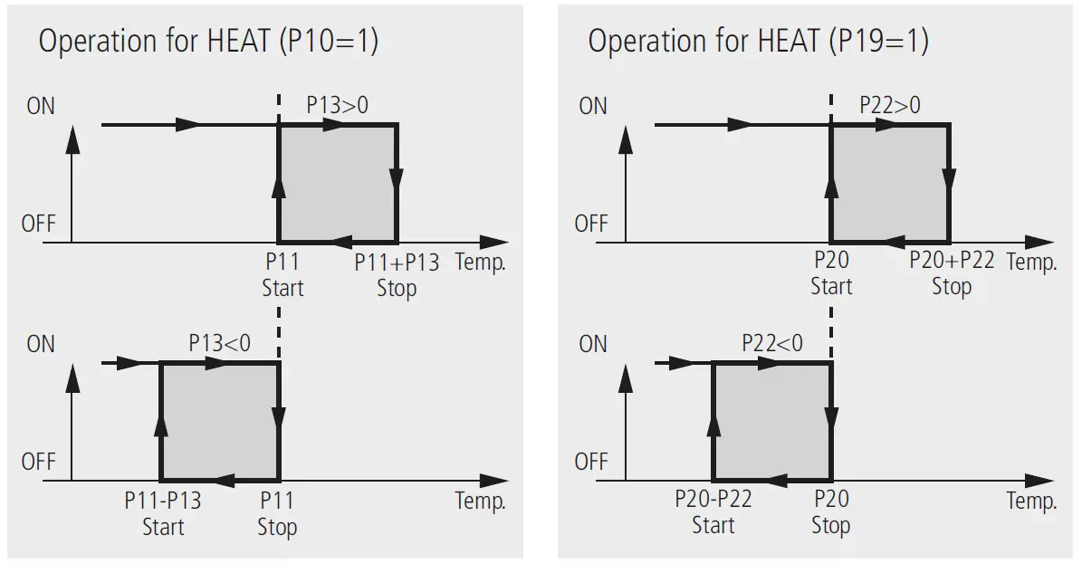
Parameters transfer
AKO-14916
Tabletop server which is connected by means of the AKO-80018, 230/12V, to the power supply. Permit to transfer parameters previously recorded in one server AKO-14918, to other panel mounting controllers without these having to be powered.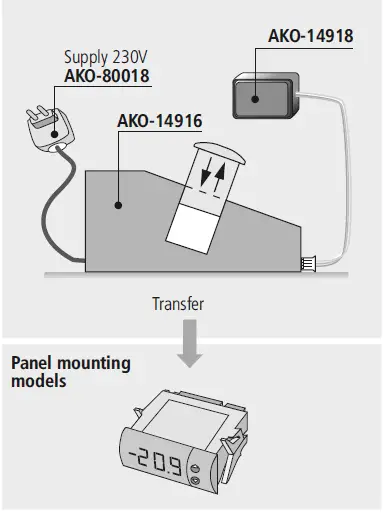
AKO-14918
A portable server without supply to which the parameters programmed in powered AKO controllers can be copied. The parameters may then be transferred from the server to other identical powered units.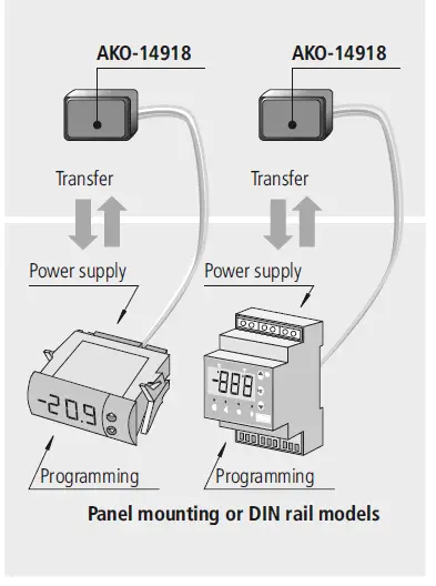
Technical data
- Temperature range . . . . . . . . . . . . . . . . . . . . . . . . . . . . . . . . -50 to 99 ºC (-58 to 211 ºF)
- NTC probe inputs . . . . . . . . . . . . . . . . . . . . . . . . . . . . . . . . . . . . . . . . . . . . AKO-149xx
- Controller accuracy . . . . . . . . . . . . . . . . . . . . . . . . . . . . . . . . . . . . . . . . . . . . . . . ± 1 ºC
- Probe tolerance at 25ºC . . . . . . . . . . . . . . . . . . . . . . . . . . . . . . . . . . . . . . . . . . ± 0.4 ºC
- Relay R1. . . . . . . . . . . . . . . . . . . . . . . . . . . . . . . . . . . . . 16 (4) A*, 250 V, cos j=1, SPST
- Relay R2 . . . . . . . . . . . . . . . . . . . . . . . . . . . . . . . . . . . . . . . 8 A*, 250 V, cos j=1, SPDT
- Maximum input power. . . . . . . . . . . . . . . . . . . . . . . . . . . . . . . . . . . . . . . . . . . . . . 5 VA
- Working ambient temperature . . . . . . . . . . . . . . . . . . . . . . . . . . . . . . . . . . . . 5 to 40 ºC
- Storage ambient temperature . . . . . . . . . . . . . . . . . . . . . . . . . . . . . . . . . . . -30 to 70 ºC
- Installation category. . . . . . . . . . . . . . . . . . . . . . . . . . . . . . . . . . II según norma CEI 664
- 3 digits and an optional decimal point when programmed . . . . . . . . . . . . . . . . . . . . . . . .
- Double insulation between the power supply, the secondary circuit and the relay output.
- * The current specified for each relay is its individual maximum. When more than one relay
- is connected, the total current cannot surpass 17,5A (EN61010) or 13A (EN60730
AKO ELECTROMECÁNICA , S.A.L. Avda. Roquetes, 30-38 08812 • Sant Pere de Ribes. Barcelona • Spain. www.ako.com


