
AKO-13012 Electronic Controllers Thermometers
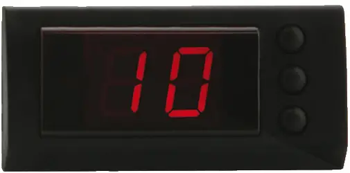
Small dimensions unit range, designed to monitor, control and regulate refrigerating generators (with manual or automatic defrost programmed by stopping the compressor) or heating generators.
Versions and references
| MODEL | FUNCTION | RELAY | POWER SUPPLY, 50/60 Hz |
| AKO-13012 | Thermometer | – | 12 V ~ ±20% |
| AKO-13020 | Thermometer | – | 120 V ~ +8% -12% |
| AKO-13023 | Thermometer | – | 230 V ~ ±10% |
| AKO-13112 | Thermostat | 16(4) A, 250 V, cos cp=1, SPST | 12 V ~ ±20% |
| AKO-13120 | Thermostat | 16(4) A, 250 V, cos cp=1, SPST | 120 V ~ +8% -12% |
| AKO-13123 | Thermostat | 16(4) A, 250 V, cos cp=1, SPST | 230 V ~ ±10% |
REMARK: A reference number followed by /**, one or two alphanumeric characters, means “with a special program”. In such a case, in addition to these general instructions,the particular instructions attached, with variations for each device should be followed.
Technical data
- Temperature range: . . . . . . . . . . . . . . . . . . . . . . . . . . . . . . . . . . . . . . . . -50 ºC to 99 ºC
- Resolution, Set Point and differential: . . . . . . . . . . . . . . . . . . . . . . . . . . . . . . . . . . . 1 ºC
- Input for NTC probe:. . . . . . . . . . . . . . . . . . . . . . . . . . . . . . . . . . . . . . . . . . AKO-149XX
- Controller accuracy: . . . . . . . . . . . . . . . . . . . . . . . . . . . . . . . . . . . . . . . . . . . . . . ± 1 ºC
- Probe tolerance at 25 ºC: . . . . . . . . . . . . . . . . . . . . . . . . . . . . . . . . . . . . . . . . . ± 0,4 ºC
- Maximum input power: . . . . . . . . . . . . . . . . . . . . . . . . . . . . . . . . . . . . . . . . . . . . . 3 VA
- Working ambient temperature:. . . . . . . . . . . . . . . . . . . . . . . . . . . . . . . . . . 5 ºC to 40 ºC
- Storage ambient temperature:. . . . . . . . . . . . . . . . . . . . . . . . . . . . . . . . . -30 ºC to 70 ºC
- Voltage pulse assigned: . . . . . . . . . . . . . . . . . . . . . . . . . . . . . . . . . . . . . . . . . . . . 800 V
Pressure ball test temperature - Accessible parts:. . . . . . . . . . . . . . . . . . . . . . . . . . . . . . . . . . . . . . . . . . . . . . 75 ºC
- Active elements positioning parts: . . . . . . . . . . . . . . . . . . . . . . . . . . . . . . . . 100 ºC
- CEM emission voltage test:. . . . . . . . . . . . . . . . . . . . . . . . . . . . . . . . . . . . . . . . . . 207 V
- CEM emission current test: . . . . . . . . . . . . . . . . . . . . . . . . . . . . . . . . . . . . . . . . . . 9 mA
Control device classification: Independent mounting, with the characteristic of automatic operation action Type 1.B, to be used in clean situation, logical medium (software) class A. Double insulation between the power supply, the secondary circuit and the relay output.
Installation
The controller must be installed in a place protected from vibrations, water and corrosive gases, and where the ambient temperature does not surpass the value specified in the technical data.In order the controllers be suitable having IP65 protection, the gasket should be installed properly between the apparatus and the perimeter of the panel cut-out where it is to be fitted. In order to give a correct reading, the probe has to be installed in a place without heat influences other than the temperature that is to be measured or controlled.
Fastening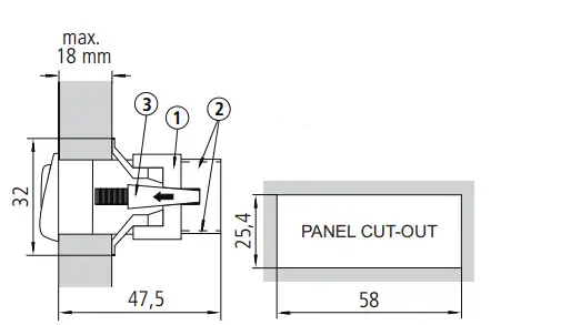
To fix the unit, place fasteners 1 over the sliders 2 as shown in the figure. Move the fasteners in the direction of the arrow. By pressing tab 3 the fasteners may be moved in the opposite direction of the arrow.
Connection
See the diagram in the unit rating plate. The probe and its lead should NEVER be installed in ducting along with power, control or power supply wiring. The power supply circuit should be connected with a minimum 2A, 230V, switch located close to the unit. The cables should be of 2 2 the type H05VV-F 2×0,75 mm or H05V-K 0,75 mm . 2 2 Section of connecting wires for relays contacts must be between 1,5 mm and 2,5 mm.
Front panel functions
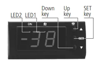
- UP key N: When pressed for at least 5 seconds, a manual defrost is started with programmed duration, (in thermostats function).
- In programming, it increases the displayed value.
- DOWN key Q: In programming, it reduces the displayed value
- SET key: When pressed for at least 5 seconds, it displays the SET POINT temperature value, (in thermostats function).In programming, accept the programmed new value.
- LED 1: Defrost in operation indicator. (in thermostats function).
- LED 2: Relay ON indicator. (in thermostats function)
- LED 2 flashing: Programming phase.
Adjustment and configuration
It should only be programmed or modified by personnel who are fully conversant with operation and possibilities of the equipment.
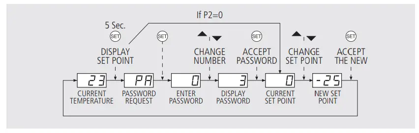
Set Point temperature
The factory SET POINT default value is 0 ºC.
- Press SET key for at least 5 seconds to DISPLAY SET POINT. It displays the CURRENT SET POINT value and LED “2” start flashing.
- Press N or Q keys for CHANGE SET POINT to the required value.
- Press SET key to ACCEPT THE NEW SET POINT. The display returns to the current temperature display status and the LED “2” stop flashing. When PA appears in display, PASSWORD programmed in L5 parameter should be enter for acceding to the CURRENT SET POINT.
- Press SET key. 0 will be displayed to ENTER PASSWORD.
- Press N or Q keys to CHANGE NUMBER and DISPLAY PASSWORD.
- Press SET key to ACCEPT PASSWORD. The CURRENT SET POINT value will be displayed and possible to be modified.
Parameters configuration
Level 1 Parameters
- Press the N + Q keys simultaneously for at least 10 seconds. The LED “2” will be flashing, we are in the LEVEL 1 PARAMETERS and in the display appear the first parameter “C0”.
- Press the N key to access the next parameter and Q key to return to the previous one.
- Pressing the SET key in the last parameter EP, the controller returns to the current temperature display status and the LED “2” will stop flashing. When PA appears in display, PASSWORD programmed in L5 parameter should be enter for accede to programming LEVEL 1 parameter.
- Press the SET key. 0 will be displayed to ENTER PASSWORD.
- Press N or Q keys to CHANGE NUMBER and DISPLAY PASSWORD
- Press the SET key to ACCEPT PASSWORD. The first parameter “C0” will be displayed.
Level 2 Values
- To DISPLAY the CURRENT VALUE of any parameter, select the required one and press the SET key. Once it is displayed, you can CHANGE VALUE by pressing N or Q key.
- Press the SET key to ACCEPT THE NEW VALUE. The programming returns to LEVEL 1 PARAMETERS.
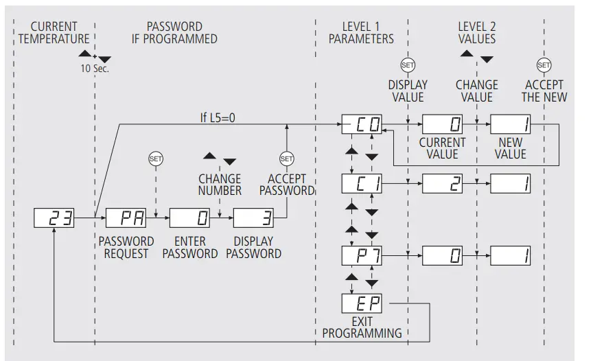
REMARK: If no key is pressed for 25 seconds in either of the previous steps, the controller will automatically return to the current temperature display status without modifying any of the parameter values.
Description of parameters and messages
The values in the Def. column are factory-set.
| Thermometers parameters | |||||||
| Thermostats parameters | |||||||
| Functions and description | Values | Min. | Def. | Max. | |||
| C0 | Sensor calibration (Offset) | ºC | -20 | 0 | 20 | • | • |
| C1 | Sensor differential (Hysteresis) | ºC | 1 | 2 | 20 | • | |
| C2 | Set Point upper limit (It cannot be set above this value) | ºC | xx | 99 | 99 | • | |
| C3 | Set Point lowers limit (It cannot be set below this value ) | ºC | -50 | -50 | xx | • | |
| C4 | Compressor protection delay type: 0=OFF/ON (From the last switch-off) 1=ON (At switch-on) | 0 | 0 | 1 | • | ||
| C5 | Protection delay time (Value for the option selected in parameter C4) | min. | 0 | 0 | 99 | • | |
| C7 | Relay time in ON in case of faulty sensor (If C7=0 and C8 0, the relay will always be OFF disconnected) | min. | 0 | 10 | 99 | • | |
| C8 | Relay time in OFF in case of faulty sensor (If C8=0 and C7 0, the relay will always be ON connected) | min. | 0 | 5 | 99 | • | |
| d0 | Defrost frequency (elapsed time between 2 starts) | h. | 0 | 1 | 99 | • | |
| d1 | Defrost maximum duration | min. | 0 | 0 | 99 | • | |
| d2 | Type of message during defrost: 0=Current temperature display; 1=Defrost start temperature display; 2=Display dF message | 0 | 2 | 2 | • | ||
| d3 | Message maximum duration (Time added at the end of defrost) | min. | 0 | 5 | 99 | • | |
| L5 | Access password to parameters | 0 | 0 | 99 | • | • | |
| L6 | Parameters transfer: 0=Disabled; 1=Send; 2=Receive | 0 | 0 | 2 | • | • | |
| PU | Program version (Information) | • | • | ||||
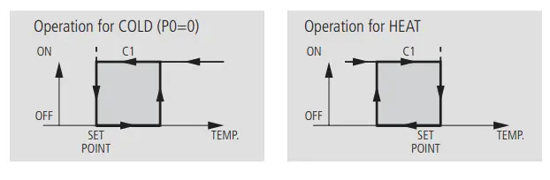
| P0 | Type of operation: 0=Cold; 1=Heat | 0 | 0 | 1 | • | ||
| P1 | Delay of all functions on power supply switch on | min. | 0 | 0 | 99 | • | |
| P2 | Allocation of password to Set Point: 0=Without allocation; 1=With allocation of L5 password | 0 | 0 | 1 | • | ||
| P3 | Initial parameters: 1=YES, configure to “Def” and exit programming if P2=0) | 0 | 0 | 1 | • | ||
| P5 | Address for units with communication (not activated) | 0 | 0 | 99 | • | • | |
| P7 | Temperature display mode: 0=Integers in ºC; 2=Integers in ºF | 0 | 0 | 2 | • | • | |
| EP | Exit programming | • | • | ||||
| Messages | |
| dF | It indicates defrosting is being carried out. In order to display “dF” during defrosting, it is essential that parameter d2 is set to option 2 |
| E1 | Sensor failure (Open circuit, crossed, temp.> 110ºC or temp.<-55ºC) |
| _ _ | Temperature > 99 ºC/ ºF |
| EE | Memory failure |
| PA | Password request to enter in programming parameters or SET POINT |
REMARK: When the time parameters are modified, the new values are applied once the current cycle is completed. In order for it to have an immediate effect, switch the controller off and then on again
Parameters transfer
AKO-14918: Portable server without supply, to which can be copied by transferred the parameters programmed in a powered unit. The parameters may then be transferred again from the server to other identical powered units. To transfer parameters, other servers are available for controllers that should be programmed identically in high quantity without power supply. 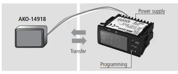
Relay operation and control
Maintenance
Clean the controller surface with a soft cloth and soap and water. Do not use abrasive detergents, petrol, alcohol or solvents.
Warnings
The use of the unit different to the manufacturer’s instructions voids the safety qualification. To ensure the correct operation of the apparatus, only NTC-type probes supplied by AKO should be used. Between –40 ºC and +20 ºC, when the probe is extended up to 1.000 m with a minimum 2 0,5mm cable, the deviation will be less than 0.25 ºC (probe extension cable ref. AKO-15586).
AKO ELECTROMECÁNICA , S.A.L.
Avda. Roquetes, 30-38
08812 • Sant Pere de Ribes.
Barcelona • Spain.
www.ako.com


