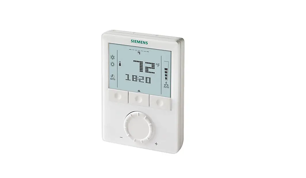
SIEMENS RDG160TU Commercial Thermostat Instruction Manual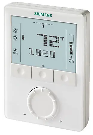
Selecting Location
Install the thermostat about 4 feet (120 cm) above the floor on an inside wall. Ensure that there is free airflow around the thermostat. Do not install the thermostat near windows or doors, in direct or radiant heat of sunlight, on unconditioned outside walls or near heating or cooling duct outlets. Not following these prerequisites will adversely affect the thermostat’s sensed temperature and its control performance. See Figure 1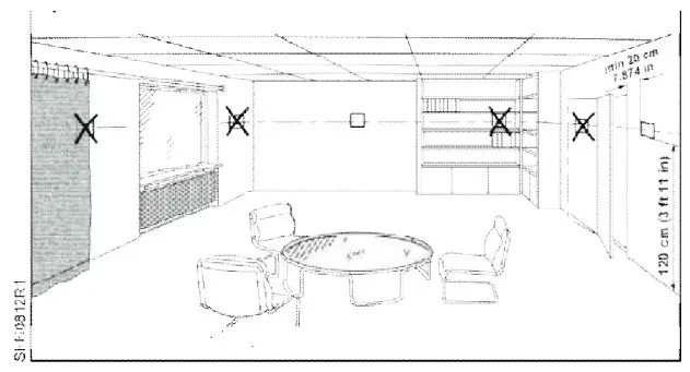
Figure 1. Mounting Location.
Installation

Step 1. Loosen retaining screws.
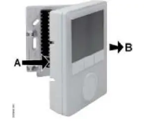
Step 2. Remove thermostat from back plate, if attached.
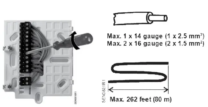
Step 3. Mount back plate at desired location and terminate wiring connections. See maximum wire size (above).
Step 4. Set application DIP switches. See DIP Switch Settings.
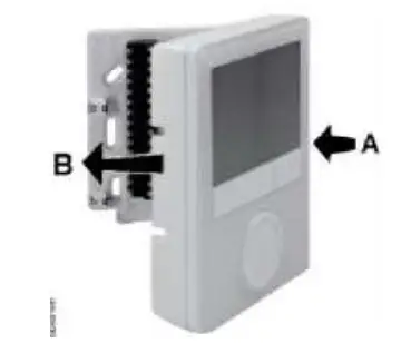
Step 5. Pivot thermostat onto back plate.
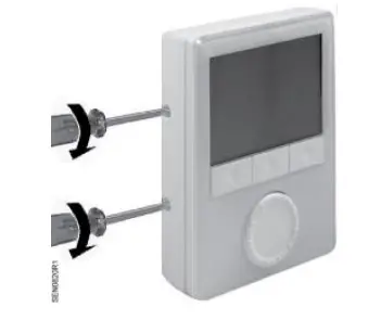
Step 6. Snap into place and tighten mounting screws.
Thermostat Termination Reference
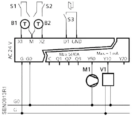
NOTE:
24 Vac power to be supplied by Class 2 rated transformer.
- G Operating voltage, 24 Vac L
- G0 Operating voltage, 24 Vac N
- X1 Input 1 signal (Digital In or 3K Ω NTC)
- X2 Input 2 signal (Digital In or 3K Ω NTC)
- M Input 1 and 2 Common
- D1 Digital input signal (example: occupancy)
- GND Digital input Common
- Q1~3 Relays outputs for 2-position valve, Speeds 1 to 3 for 3-speed fan
- Y50 0 to 10V output for ECM Fan
- Y10 0 to 10V output for H/C valve (2-pipe) or Heating valve (4-pipe) applications
- Y20 0 to 10V output for Radiator or Electric heat (2-pipe) or Cooling valve (4-pipe) applications
- C 24 Vac L for relay outputs
Setting Up Applications
Use the DIP switches to set up Basic Applications.
Use the Control Parameter set up on the front panel to set up additional application customization or special set up can be set up. See Parameter Set Up in Service Level.
If no Applications are set up, the front panel displays NO APP.
Diagnostics Mode
In addition to standard Service level control parameter set up, the RDG160TU also has an Expert Level for the advanced user to perform diagnostics and troubleshooting. SeeTable 3.
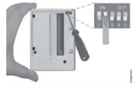
DIP Switch Settings Overview
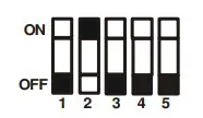
Applications are set up with DIP switches 1 through 3.
DIP Switch 4 selects ECM Fan (OFF) or 3-Speed Fan (ON).
DIP Switch 5 (ON) disables time program functions; time is not displayed.
Following is the set up of the most common applications and any supporting parameters to be set using the Service Menu after installation. For other application settings or detailed control functions, see Room Thermostats with LCD for Wall Mounting RDG100, RDG100T, RDG110, RDG140, RDG160, RDG100T/H Basic Documentation (CE1P3181).
| HEAT PUMP(Manual changeover only, no reversing valvesupport) | Heat OR Cool Compressor (Q1) Only | Heat OR Cool Compressor (Q1) with2-Position Electric Heat (Q2) | Heat (Q1) ANDCool (Q2) Compressors | 2-Stage Heat OR Cool(Q1, Q2) |
| ECM Fan (Y50) | 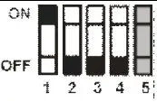 P46 = 1 | 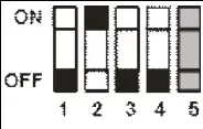 P46 = 1 P47 = 1 | 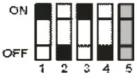 P46 = 1P47 = 1 | 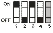 |
| 2-PIPE FCU | 2-Position Valve (Q1) | Modulating Valve (Y10) | 2-PIPE FCU with HEAT | 2-Position Valve (Q1) with ON-OFF Electric Heat (Q2) | Modulating Valve (Y10) with Modulating Electric Heat (Q2) | Valve (Y10) with Modulating Electric Heat (Q2) Modulating Valve (Y10) with Modulating Electric Heat (Y20) | 2-PIPE FCU with RADIATOR | 2-Position Valve (Q1) with 2-Position Radiator (Q2) | Modulating Valve (Y10) with 2-Position Radiator (Q2) | Modulating Valve (Y10) with Modulating Radiator (Y20) |
| ECM Fan (Y50 | P46 = 1 | | ECM Fan (Y50) | P46 = 1 P47 = 1 | P46 = 2 P47 = 1 | | ECM Fan (Y50) | 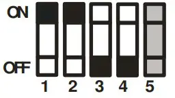 P46 = 1 P47 = 1 | P46 = 2 P47 = 1 | |
| 3-Speed Fan (Q1-Q3) | | 3-Speed Fan (Q1-Q3) | | 3-Speed Fan (Q1-Q3) | | |||||
| Chilled / Heated Ceiling | / Heated Ceiling 2-Position Valve (Q1) | Modulating Valve (Y10) | 2-Position valve (Q1) with 2- Position Electric Heater (Q2) | Modulating Valve (Y10) with 2-Position Electric Heater (Q2) | Modulating Valve (Y10) with Modulating Electric Heater (Y20) | 2-Position Valve (Q1) with 2-Position Radiator Q2) | Modulating Valve (Y10) with 2-Position Radiator (Q2) | Modulating Valve (Y10) with Modulating Radiator (Y20) | ||
P46 = 1 | | P46 = 1 P47 = 1 | P46 = 2 P47 = 1 | | P46 = 1 P47 – 1 | P46 = 2 P47 = 1 | |
| 4-PIPE FCU | 2-Position Heating (Q1) and Cooling (Q2) Valves | Modulating Heating (Y10) and Cooling (Y20) Valves | 2-STAGE | 2-Position Heating (Q1) and Cooling (Q2) Valves | Modulating Heating (Y10) and Cooling (Y20) Valves |
| ECM Fan (Y50 | 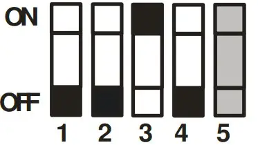 P46 = 1 P47 = 1 | | ECM Fan (Y50) | P46 = 1 P47 = 1 | |
| 3-Speed Fan (Q1-Q3) | | 3-Speed Fan (Q1-Q3) | |
Parameter Set Up in Service Level
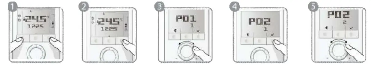
To change control parameters, do the following:
- Press the HEAT/COOL and FAN/OK buttons simultaneously for at least 4 seconds.
- Release them and, within 2 seconds, press the HEAT/COOL button again until P01 displays.
- Select the required parameter by turning the rotary knob.
- Press the FAN/OK button . The selected parameter value blinks. Change the value by turning the rotary knob.
- Press the FAN/OK button to confirm the change, or the HEAT/COOL button (Esc) to cancel the change.
- Repeat Steps 3 through 5 for more parameters or press HEAT/COOL (Esc) to exit.
To return to the factory-default control parameters, do the following:
- Change the value of Parameter P71 to ON.
- Press the FAN/OK button to confirm the change. When reloading, the screen displays 8888.
When reloading, the screen displays 8888.
NOTES
- Use Comfort mode for Occupied settings.
- Use Economy mode for Unoccupied settings.
- Use Protection mode for Frost Protection.
Table 1. Service Level Parameters.
| Parameter | Name | Factory Setting | Range | Dependencies |
| P01 | Control sequence | With 2-pipe/2-stage: 1 = cooling only With 4-pipe:4 = H/C | 0 = Heating only 1 = Cooling only2 = H/C changeover manual3 = H/C changeover automatic 4 = Heating and cooling | |
| P02 | Operating mode profile (operating mode button) | 1 | 1 = (Auto) – Comfort – Protection 2 = (Auto) – Comfort – Economy –Protection3 = Comfort – Protection4 = Comfort – Economy – Protection | P01 |
| P03 | Fan mode selection | 0 | 0 = Auto – Manual 1 = Manual2 = Auto – Manual – Protection3 = Auto – Protection | P52 |
| P04 | Selection of °C or °F | Also set during initial set-up | 0 = Degrees Celsius (°C)1 = Degrees Fahrenheit (°F) | |
| P05 | Sensor calibration (internally, externally) | 0°F (0°C) | – 6°F to 6°F (-21°C to -14°C) | |
| P06 | Standard temperature display | 0 | 0 = Room temperature 1 = Setpoint | |
| P08 | Comfort setpoint | 70°F (21°C) | 41°F to 104°F (5°C to 40°C) | |
| P09 | Minimum setpoint for Comfort mode | 41°F (5°C) | 41°F to 104 °F (5°C to 40°C) | |
| P10 | Maximum setpoint for Comfort mode | 95°F (35°C) | 41°F to 104°F (5°C to 40°C) | |
| P11 | Economy heating setpoint | 59°F (15°C) | OFF, 41°F to 104°F (5°C to 40°C max.) | |
| P12 | Economy cooling setpoint | 86°F (30°C) | OFF, 41°F to 104°F; 5°C to 40°C (min.) | |
| P13 | Electric heater in cooling mode | ON | ON = Enabled OFF = Disabled | Application |
| P14 | Button lock function | 0 | 0 = Unlocked 1 = Auto lock2 = Manual lock | |
| P15 | Fan stage in deadband (Comfort mode) | 0 | 0 = Disabled1 = Stage 1 (heating and cooling) 2 = Stage 1 (cooling only) |
Diagnostics and Testing using Expert Level
To change control parameters, do the following:
- Press the HEAT/COOL and FAN/OK buttons simultaneously for at least 4 seconds.
- Release them, and within 2 seconds, press the FAN/OK button again until the temperature does not display.
- Turn the rotary knob counterclockwise a minimum 1/2 rotation.
Pxx displays. Select the required parameter by turning the rotary knob. - Press the FAN/OK button . The current value of the selected parameter blinks and can be changed by turning the rotary knob.
- Press the FAN/OK button to confirm the adjusted value or press the HEAT/COOL button (Esc) to cancel the change.
- To adjust additional parameters, repeat Steps 3 through 5.
- Press the HEAT/COOL button (Esc) to exit the parameter setting mode.
To return to the factory-default control parameters, do the following:
- Change the value of Parameter P71 to ON.
- Press the FAN/OK button to confirm the change.
When reloading, the screen displays 8888.
NOTES
- Parameters P46 and P47: Use DIP switches 4 and 5 to set to 2-position or 3 position.
- Parameter P45 compensates for heat dissipation of the electric heater relay.
- If no sensors or switches are connected, it is not necessary to disable the inputs (P38, P40 or P42 = no function), the thermostat recognizes if a sensor is connected (but diagnostic displays Err).
Table 2. Expert Level Parameters.
| Parameter | Name | Factory Sett | Range | Dependencies |
| P30 | P-band/switching differential in heating mode | 4°F (-15°C) | 1°F to 12°F (-17°C to -11°C) | |
| P31 | P-band/switching differential in cooling mode | 2°F (-16°C)) | 1°F to 12°F (-17°C to -11°C) | |
| P32 | P-band/switching differential for radiator | 4°F (-15°C) | 1°F to 12°F (-17°C to -11°C) | Application |
| P33 | Deadband in Comfort mode | 4°F (-15°C) | 1°F to 10°F (-17°C to -12°C) | Application |
| P34 | Setpoint differential (wD) | 4°F (-15°C) | 1°F to 10 F (-17°C to -12°C) | Application |
| P35 | Integral action time | 45 minutes | 0 to 120 minutes | P46, P47 |
| P36 | Heating/cooling changeover switching point cooling (X1/X2) | 61°F (16°C) | 50°F to 77°F (10°C to 25 C) | P38, P40 |
| P37 | Heating/cooling changeover switching point heating (X1/X2) | 82°F (27°C) | 81°F to 104°F (27°C to 40°C) | |
| P38 | Functionality of X1 | 1 = External sensor | 0 = — (No function) 1 = Room temp ext/ret air temp (AI) 2 = H/C changeover (AI/DI) 3 = Operating mode contact [DI) 4 = Dewpoint sensor (DI) 5 = Enable electric heater (DI) 6 = Fault input (DI) 9 = Supply air sensor | |
| P39 | Operating action of X1 if digital input | NO | NO = Normally open/open NC = Normally closed/closed | P38 |
| P40 | Functionality of X2 | 2 = H/C changeove | 0 = — (No function) 1 = Room temp ext/ret air temp (AI) 2 = H/C changeover (AI/DI) 3 = Operating mode contact [DI) 4 = Dewpoint sensor. (DI) 5 = Enable electric heater (DI) 6 = Fault input (DI) 9 = Supply air sensor | |
| P41 | Operating action of X2 if digital input | NO | NO = Normally open/open NC = Normally closed/closed | P40 |
| P42 | Functionality of D1 | 3 = Operating mode changeover | 0 = — (no function) 2 = H/C changeover (DI) 3 = Operating mode contact [DI) 4 = Dewpoint sensor (DI) 5 = Enable electric heater (DI) P406 = Fault input (DI) | |
| P43 | Operating action of D1 if digital input | NO | NO = Normally open/open NC = Normally closed/closed | P42 |
| P45 | Power of electric heater on Q2 (for adaptive temperature compensation) | 0 kW | 0.0 to 1.2 kW | |
| P46 | Outputs Y10 (DC) or Q1 (2-pos) | DC 0 to 10V (2) | 1 = On/Off 2 = DC 0 to 10V | Application |
| P47 | Outputs Y20 (DC) or Q2 (2.pos) | DC 0 to 10V (2) | 1 = On/Off 2 = DC 0 to 10V | Application |
| P48 | Min. output on time 2-position control output | 1 minute | 1 to 20 minutes | P46 |
| P48 | Min. output ON time on Q1, Q2 and Q3, Relay function P72, P73, P74 ( =2,3,4,5): | 1 minute | 1 to 20 minutes | Application P7x |
| P49 | Min. output off time 2-position control output | 1 minute | 1 to 20 minutes | P47 |
| P49 | Min. output OFF time on Q1, Q2 and Q3 Relay function P72, P73, P74 ( =2,3,4,5): | 1 minute | 1 to 20 minutes | Application P7x |
| P50 | Purging function (only when changeover with local sensor is selected) | OFF | OFF: Not active 1 to 5 min: Active with selected duratio | |
| P51 | Floor heating limit temperature | OFF | OFF, 50°F to 122°F (10°C to 50°C) | |
| P52 | Fan operation | 1 | 0 = Disabled 1 = Enabled 2 = Heating only 3 = Cooling only | |
| P53 | Fan speed | DC 0 to 10V | 1 = 1-speed fan 2 = 3-speed fan 3 = DC 0 to 10V (ECM fan) | P52 DIP4 |
| P54 | Fan overrun time (only when electric heater is used) | 60 seconds | 0 to 360 seconds | P52 |
| P55 | Switching point fan speed high | 100% | 80 to 100% | P52 |
| P56 | Switching point fan speed medium ECM fan min. output | 65% ECM: 30% | 30% to 75% ECM: 1% to fan max. | P52 |
| P57 | Switching point fan speed low ECM: Switching point fan | 10% ECM:10% | 1% to 15% ECM: 1% to 100% | P52 |
| P58 | Fan start booster | ON | ON: Enabled OFF: Disabled | P52 |
| P59 | Fan min. on time | 2 minutes | 1 to .6 minutes | P52 |
| P60 | Fan kick interval in Comfort mode (time until next kick) | OFF | 0 to 89 minutes, OFF | P52 |
| P61 | Fan kick interval in Economy mode (time until next kick) | OFF | 0 to 359 minutes, OFF | P52 |
| P62 | Clean filter reminder running time | OFF (0) | OFF, 100 to 9900 hours | P52 |
| P63 | Minimum supply air temperature | OFF, 32°F to P64 °F (0°C to P64 °C) | P38, P40 | |
| P64 | Maximum supply air temperature | OFF | OFF, P63 °F to 122°F (P63 °C to 50°C) | P38, P40 |
| P65 | Protection heating setpoint | 8°C | OFF, 41°F to 104°F (5°C to 40°C max.) | |
| P66 | Protection cooling setpoint | OFF | OFF, 41°F to 104°F; 5°C to 40°C (min.) | P52, P46, P47 |
| P67 | Fan start delay | 0 seconds | 0 through 360 seconds | P02 |
| P68 | Extension Comfort period | OFF F (0) | OFF(0); 15 through 360 minutes | |
| P69 | Temporary setpoint Comfort mode (see also Comfort setpoint P08) | OFF | OFF = Disabled ON = Enabled | |
| P70 | Infrared receiver (Not available) | ON | OFF = Disabled ON = Enabled | |
| P71 | Reload factory settings | OFF | OFF = Disabled ON = Reload start | Application |
| P72 | Output Q1 function | 0 | 0 = No function 1= Switch OFF in Protection 2= Switch ON in H/C demand (2-pipe) 3= Switch ON in H demand (4-pipe) 4= Switch ON in C demand (4-pipe) 5= Status active sequence (H or C) | Application |
| P73 | Output Q2 function | 0 | 0 = No function 1= Switch OFF in Protection 2= Switch ON in H/C demand (2-pipe) 3= Switch ON in H demand (4-pipe) 4= Switch ON in C demand (4-pipe) 5= Status active sequence (H or C) | Application |
| P74 | Output Q3 function | 0 | 0 = No function 1= Switch OFF in Protection 2= Switch ON in H/C demand (2-pipe) 3= Switch ON in H demand (4-pipe) 4= Switch ON in C demand (4-pipe) 5= Status active sequence (H or C) | Application |
Table 3. Diagnostics and Tests.
| Parameter | Name | Factory Setting | Range | Dependencies |
| d01 | Application type | Diagnostics | 0 = (no application) 1 = 2-pipe2 = 2-pipe with electric heater 3 = 2-pipe with radiator4 = 4-pipe5 = 2 stage heating or cooling 6 = 4-pipe with electric heater | |
| d02 | X1 status | Diagnostics | “—” = Function not selected 0 = Not activated (for DI)1 = Activated (DI)32°F to 120°F (0°C to 49°C)= Curr. temp. value (for AI) Err *)00 = H/C input closed100 = H/C input open | |
| d03 | X2 status | Diagnostics | “—” = Function not selected 0 = Not activated (for DI)1 = Activated (DI)32°F to 120°F (0°C to 49°C)= Curr. temp. value (for AI) Err *)00 = H/C input closed100 = H/C input open | |
| d04 | D1 status | Diagnostics | “—” = Function not selected 0 = Not activated (for DI)1 = Activated (DI)00 = H/C input closed100 = H/C input open | |
| d07 | Software version | — | Ux.xx displays | |
| d08 | Test mode for checking Q1 output | — | “—” = No signal at output Q1OPE = Output Q1 forced opening CLO = Output Q1 forced closing | P72,Application |
| d09 | Test mode for checking Q2 output | — | “—” = No signal at output Q2OPE = Output Q2 forced opening CLO = Output Q2 forced closing | P73,Application |
| d10 | Test mode for checking Q3 output | — | “—” = No signal at output Q3OPE = Output Q3 forced opening CLO = Output Q3 forced closing | P74,Application |
Dimensions
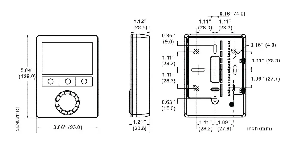
Figure 2. Dimensions in Inches (Millimeters).
Information in this publication is based on current specifications. The company reserves the right to make changes in specifications and models as design improvements are introduced. Product or company names mentioned herein may be the trademarks of their respective owners. © 2016 Siemens Industry, Inc.
Siemens Industry, Inc.
Building Technologies Division
1000 Deerfield Parkway
Buffalo Grove, IL 60089
USA
Tel. + 1 847-215-1000
Your feedback is important to us. If you have
comments about this document, please send them to
[email protected]
Document No. 129-588
Printed in the USA


