Dettson R02P034 Communicating Thermostat
FAILURE TO READ AND FOLLOW ALL INSTRUCTIONS CAREFULLY BEFORE INSTALLING OR OPERATING THIS CONTROL AND SYSTEM COULD CAUSE PERSONAL INJURY AND/OR PROPERTY DAMAGE.
PRODUCT OVERVIEW
The R02P034 is our most powerful thermostat yet. Control your home comfort system powered by an improved full LED display control unit with touch sensitivity. Adjust the desired temperature with a wide setpoint range of 41°F to 95°F.
The unit works well with 24 VAC ClimateTalkTM architecture; powered by gas, electric heat, heat pumps, and central air conditioning based systems. With smart systems such as autoconfigure, a utochangeover and advance diagnostics, you can take a hands off aproach, while letting it do the heavy lifting for you. Additional features include humidity control, dehumidification control, dual fuel control, and filter change-out indicator. The R02P034 is the full package in home control systems.
![]() WARNING Thermostat installation and all components of the control system shall conform to Class II circuits per the NEC/CEC code.
WARNING Thermostat installation and all components of the control system shall conform to Class II circuits per the NEC/CEC code.
![]() WARNING To prevent electrical shock and/or equipment damage, disconnect electric power to system at main fuse or circuit breaker box until installation is complete.
WARNING To prevent electrical shock and/or equipment damage, disconnect electric power to system at main fuse or circuit breaker box until installation is complete.
ATTENTION: MERCURY NOTICE This product does not contain mercury, but it may replace a product that contains mercury. Mercury and products containing mercury must not be discarded in household trash. Do not touch any spilled mercury. Wearing nonabsorbent gloves, clean up any spilled mercury and place it in a sealed container. For proper disposal of a product containing mercury or a sealed container of spilled mercury, place it in a suitable shipping container. On the Internet, visit www.switchthestat.ca. com for a location where the product containing mercury can be sent.
Installation
This booklet contains installation instruction and information on the thermostat only. Separate installation instructions for the furnace or air handler and outdoor AC condensing unit or heat pump are provided.
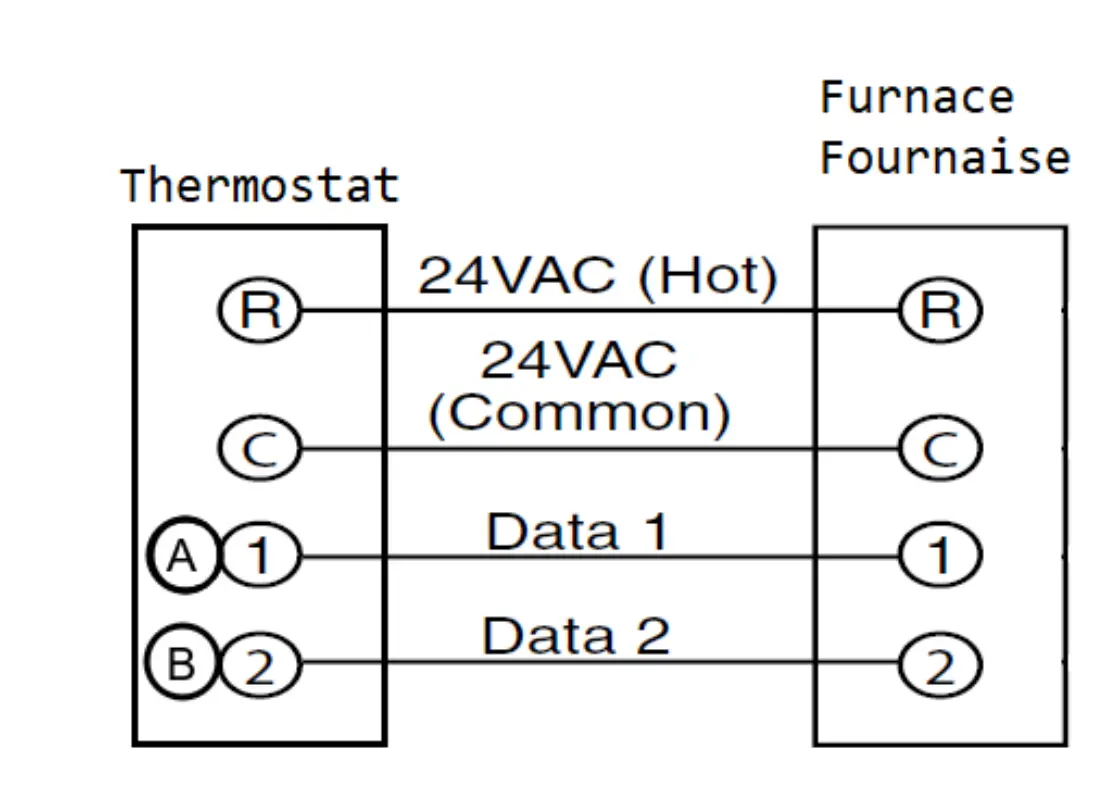
Wiring Requirements
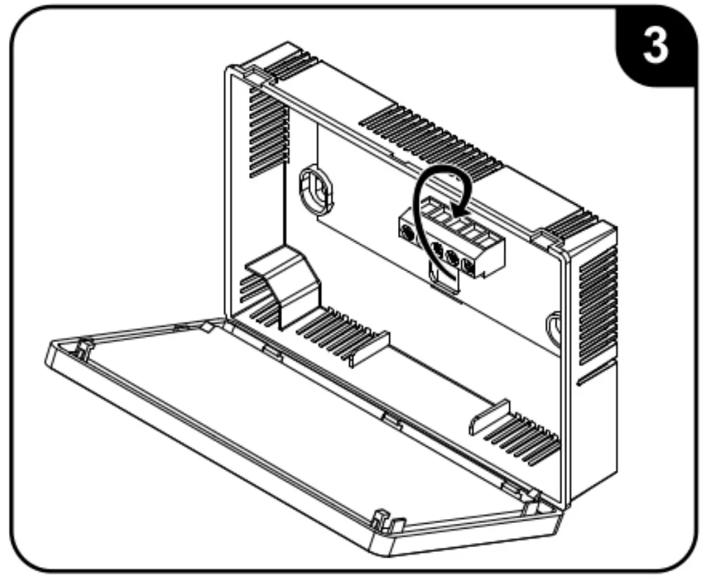
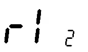
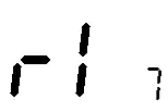
Each communicating device in the system has a four wire connection labelled (R, C, 1, 2). Each R, C, 1, and 2 terminals must be wired consistently. Maximum length from the thermostat to the indoor unit is 100 feet.
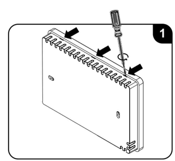
Installing Thermostat
The thermostat should be placed where the temperature is representative of the general room
conditions, away from cold or warm air draughts, radiant heat and direct sunlight. The thermostat must not be installed on an outside wall.
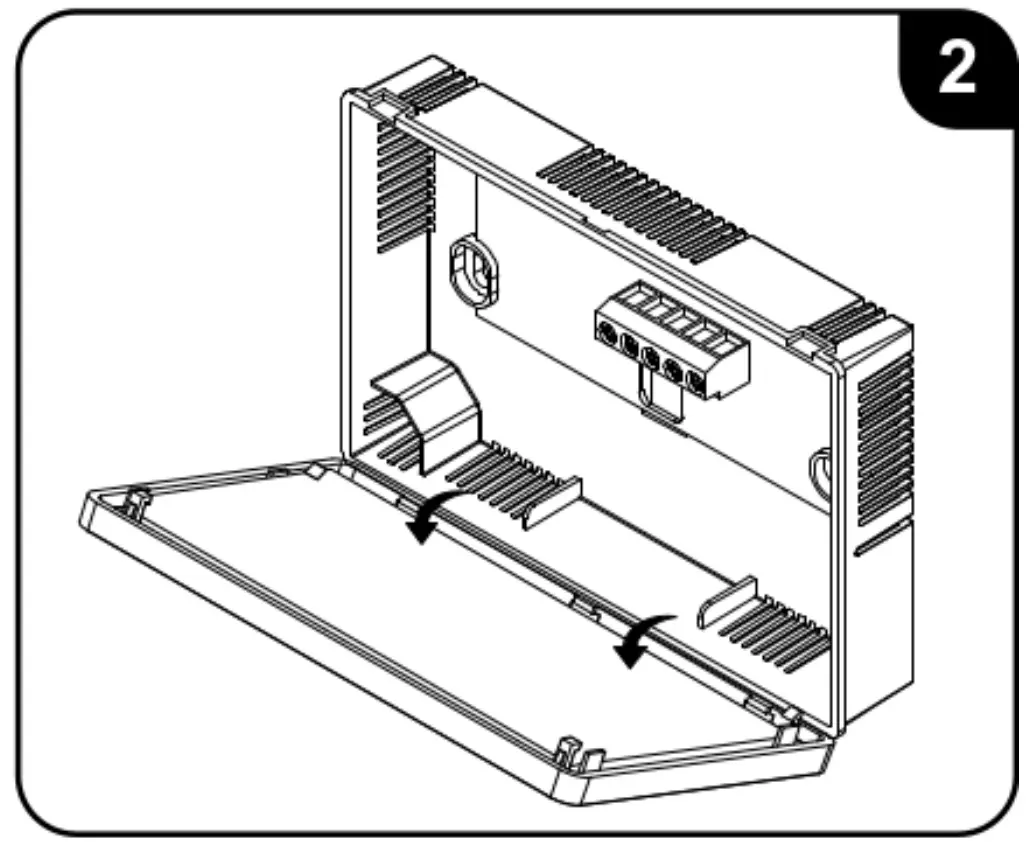
- Using a flat a screwdriver, carefully separate the the top of the thermostat body from the base.

- Swing the base open and detach it from the body.

- Connect wires to terminal block on base.
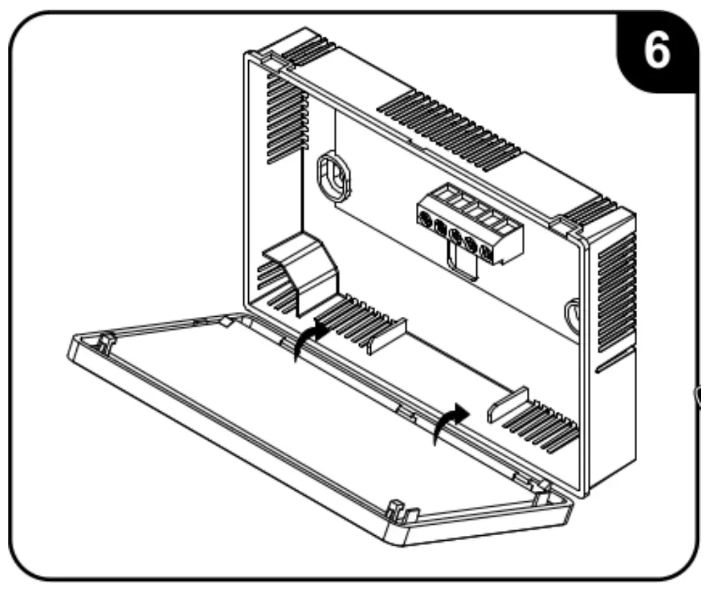
- Push excess wire into wall and plug hole with a fire resistant material (such as fiberglass insulation) to prevent drafts from affecting thermostat operation.
- Attach base snugly to wall using the two provided mounting screws. Levelling is for appearance only and will not affect thermostat operation.
- Carefully line up the bottom of the thermostat with the base and snap into place.


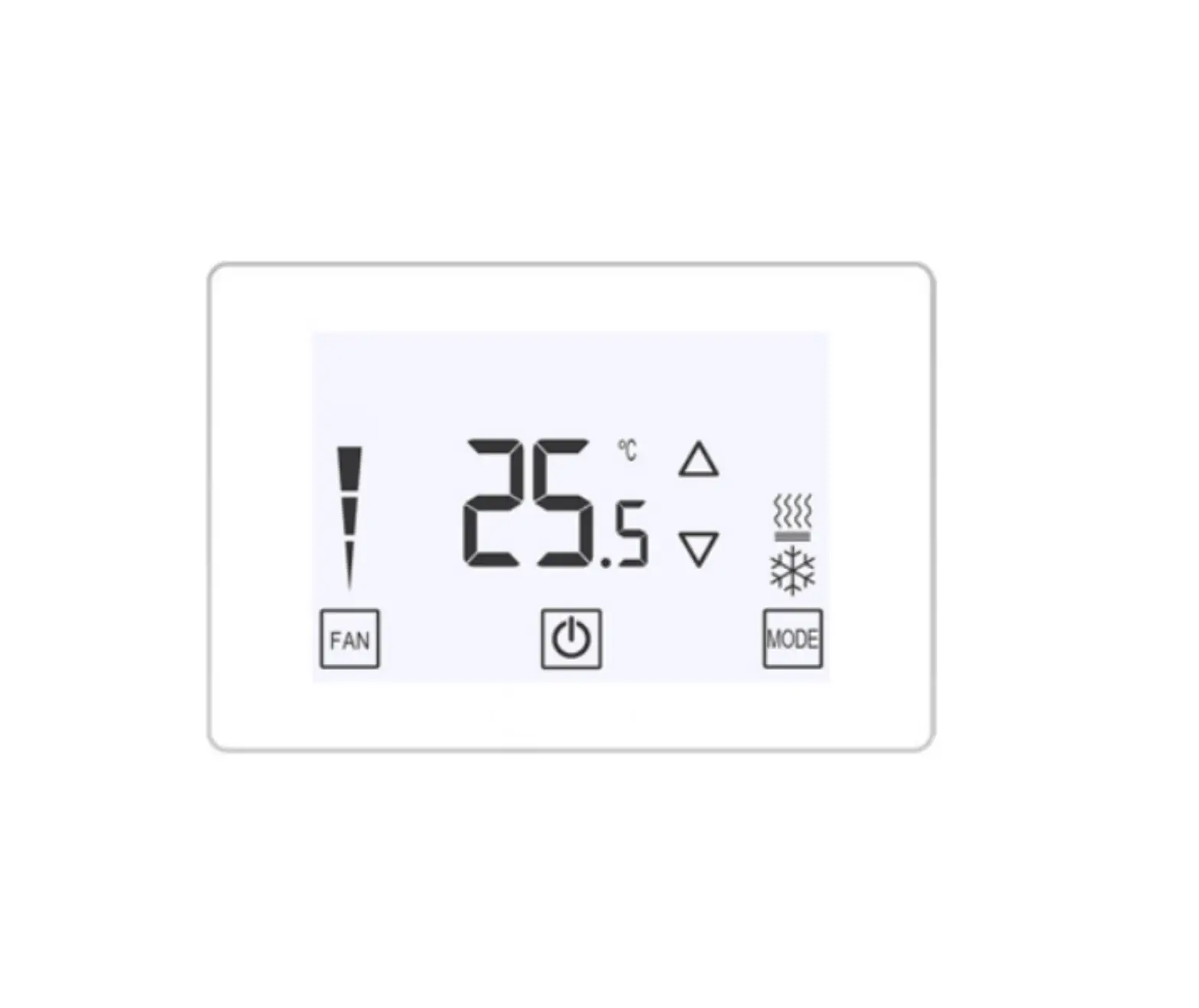
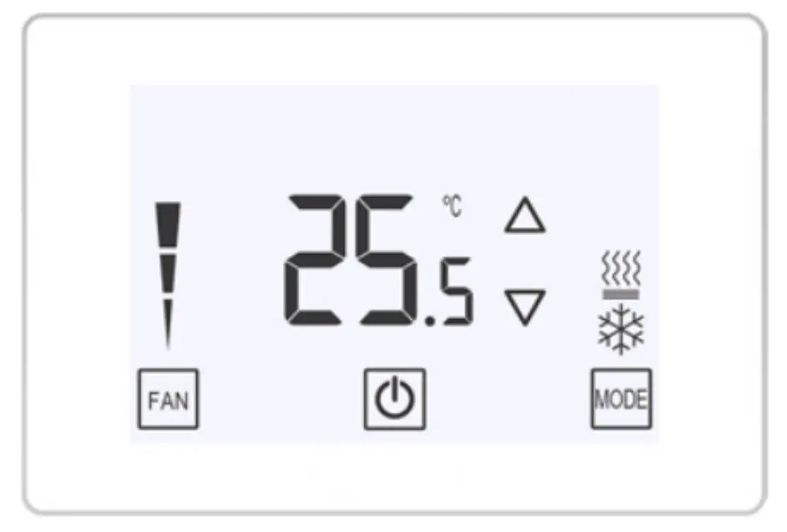
Operation
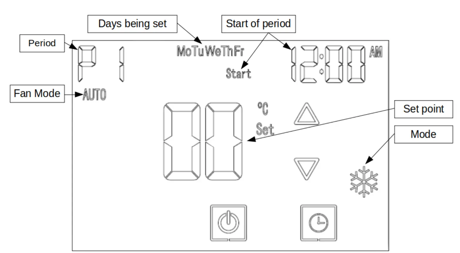
Display and Controls
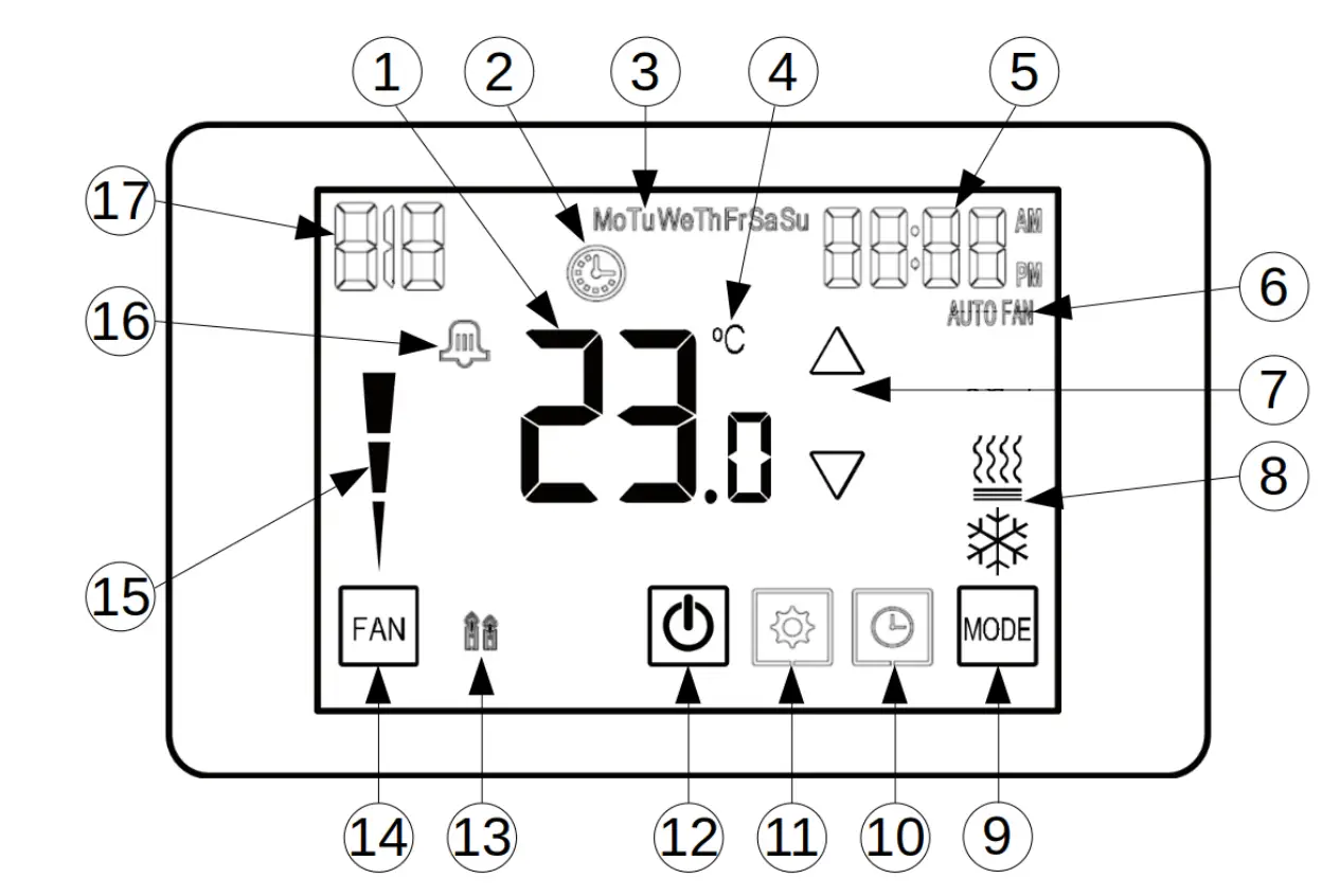
- Temperature display
- Thermostat waiting
- Week day
- Temperature scale
- Time display (or menu item value)
- Continuous fan mode
- Adjustment buttons
- Operating mode
- Mode select button
- Clock setting button
- Settings button
- On/Off button
- Auxiliary heat display
- Fan mode button
- Modulation indicator
- Error/Alarm indicator
- Humidity, outdoor temperature or alarm display
System Modes
On/Off
The![]() button allows to completely turn off the system. Then, no heating, cooling or ventilation command will be sent to the system.
button allows to completely turn off the system. Then, no heating, cooling or ventilation command will be sent to the system.
This button also allows to exit any settings menu.
Fan Modes
Press![]() to switch between Fan On and Fan Auto. When the thermostat displays AUTO FAN, the circulating fan will run only when there is a heating or cooling demand. Otherwise, the fan will run continuously.
to switch between Fan On and Fan Auto. When the thermostat displays AUTO FAN, the circulating fan will run only when there is a heating or cooling demand. Otherwise, the fan will run continuously.
Operating Modes
The operating mode can be changed using the ![]() key.
key.
Heat ![]() : Heating with the primary heating source (heat pump if present, or furnace).
: Heating with the primary heating source (heat pump if present, or furnace).
Auxiliary Heat (![]() and
and ![]() ): Heating with the auxiliary heating source (furnace). This is only available when a heat pump is connected.
): Heating with the auxiliary heating source (furnace). This is only available when a heat pump is connected.
Cool ( ![]() ): Cooling mode is only available when a heat pump or A/C unit is connected.
): Cooling mode is only available when a heat pump or A/C unit is connected.
Auto (![]() and
and![]() ): The thermostat will automatically switch between heating and cooling modes. When there is a demand for the selected mode, the matching icon will start blinking and the thermostat will command the system to operate.
): The thermostat will automatically switch between heating and cooling modes. When there is a demand for the selected mode, the matching icon will start blinking and the thermostat will command the system to operate.
Clock Setting
To set the time and day, press the button. ![]() Clock will be displayed. Use the
Clock will be displayed. Use the![]() and
and ![]() buttons to adjust the blinking value. Press
buttons to adjust the blinking value. Press![]() to switch between setting the hours, minutes and day.
to switch between setting the hours, minutes and day.
Once completed, press![]() to return to the main display
to return to the main display
Schedule Setting
By default, the scheduling mode is disable. Refer to section 3 to set the desired schedule type.
When scheduling is enabled, press ![]() to enter clock configuration (see section 2.3). Using the button
to enter clock configuration (see section 2.3). Using the button![]() to skip over the clock parameters, the schedule paramaters will be displayed
to skip over the clock parameters, the schedule paramaters will be displayed
Start is displayed indicating the start time of the current period is being set. Use![]() and
and![]() to adjust the blinking parameter, and use
to adjust the blinking parameter, and use![]() to advance to the next one, in this order:
to advance to the next one, in this order:
- Period start time (hours)
- Period start time (minutes)
- Operating mode during the period
- Fan mode
- Modulation (unused)
- Set point
The blinking cursor will cycle through these parameters for all periods, and for all day groups. Once the schedule is set, to enter this mode press and hold ![]() at the main display.
at the main display.
Alarms
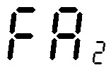
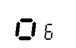
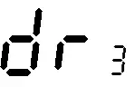
The thermostat will display ![]() when an alarm is raised. The alarm code will be shown in the top-left corner.
when an alarm is raised. The alarm code will be shown in the top-left corner.
| Display Code | Description | Action |
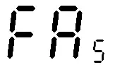
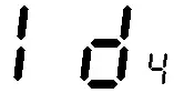
 | Air filter cleaning reminder | Clean or replace the air filter, and reset the filter counter setting (P41) |
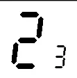
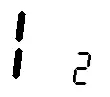
 | Defective temperature sensor | Replace the thermostat |
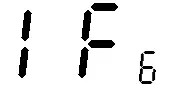
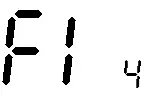
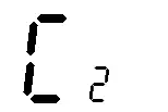
 | Communication error | Check equipment and wiring |
Thermostat Settings
Press![]() to access the settings menu.
to access the settings menu.
Use ![]() and
and ![]() to change the parameter value.
to change the parameter value.
Use ![]() to move to next parameter and to move to the previous parameter.
to move to next parameter and to move to the previous parameter.
Use ![]() to exit to the main display.
to exit to the main display.
| Item | Description | Range | Defualt | Note |
| P1 | Temperature adjustment | -6 to 6°C / -12 to 12°F | 0°C / 0°F | |
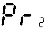
| P2 | Min. set point | 5 to 35°C / 41 to 95°F | 10°C / 50°F | Cooling |
| P3 | Max. set point | 5 to 35°C / 41 to 95°F | 30°C / 86°F | Heating |
| P22 | Continuous fan ratio | 30 to 70% | 30% | |
| P30 | Beeper | 0 / 1 | 1 | 0: Disabled 1: Enabled |
| P40 | Air filter counter | 0 – 999 hours | – | Read-only |
| P41 | Air filter counter reset | 0 / 1 | 0 | 0: Do not reset 1: Reset |
| P42 | Air filter alarm delay | 0 – 999 hours | 0 | 0: Disabled |
| P49 | Heat/cool switchover | 0 to 10°C / 0 to 20°F | 2.0°C / 4.0°F | Auto mode only |
| 100 | Dimming | 0 / 1 | 1 | 0: Disabled 1: Enabled |
| 102 | Dimming brightness | 0 to 90% | 10% | |
| 105 | Brightness | 50 to 100% | 100% | |
| 107 | Schedule program | 0 – 4 | 0 | 0: Disabled 1: 1 day 2: 5+2 days 3: 5+1+1 days 4: 7 days |
| 108 | Day periods | 0 / 1 | 1 | 0: 2 periods 1: 4 periods |
| 109 | Clock format | 0 / 1 | 0 | 0: 12h 1: 24h |
| 122 | Cool modulation speed | 0 – 100 sec. | 3 sec. | |
| 123 | Heat modulation speed | 0 – 100 sec. | 3 sec. | |
| 124 | Balance point | -30 to 15°C / -22 to 59°F | -20°C / -4°F | |
| 125 | Aux. heat temp. diff. | -1 to -4°C / -1 to -7°F | -1.5°C / -2°F | |
| 187 | Humidity or outdoor temp. display | 0 / 1 | 1 | 0: Disabled 1: Enabled |
| 191 | Display selection (187) | 0 / 1 | 0 | 0: Humidity 1: Outdoor temperature |
| 194 | Humidity deadband | 2 to 20% | 5% | |
| 195 | Humidity adjustment | -9 to 9% | 0% | |
| 197 | Humidity set point | 20 to 100% | 45% | |
| 199 | Temperature unit | 0 / 1 | 1 | 0: °F 1: °C |
| 200 | Factory reset | 0 / 1 | 0 | 0: Do not reset 1: Reset |
Equipment operating information and options can be accessed by long pressing the ![]() button.
button.
Use ![]() and
and ![]() to select the menu item, or to change the parameter value.
to select the menu item, or to change the parameter value.
Use ![]() to confirm the selection.
to confirm the selection.
Use ![]() to return to the upper menu.
to return to the upper menu.
Use ![]() to exit to the main display.
to exit to the main display.
On entering this menu, you will have to select the equipment to be accessed.
| Display | Description |
 | Furnace |
 | Interface board |
Each Equipment User Menu has submenus to divide the information into categories. Each piece
of equipment has a different set of submenus, with different parameters. The submenus and the information they provide are represented in the following tables.
A X in the following tables indicate alpha or numerical character. For more information on each menu item, refer to the manual of the corresponding equipment.
Chinook Gas Furnace User Menus
| Main Menus | ||
| Code | Menu | Description |
 | Status | Used to display equipment information |
 | 2 Week History | Display operating info. of last 2 weeks |
 | Life History | Display total operating info. |
 | Fault History | Display info. on last 6 error codes |
 | Unit Info | Display model and serial numbers |
 | Setup | Adjustable settings |
| ST1 – Status 1 | |||
| Code | Parameter | Indications | Comments |
 | Main Limit | Closed , Open | Main limit control status |
 | MRLC Input | Closed , Open | Main reset limit control status |
 | HALC Input | Closed , Open | Heat assist limit control status |
 | IDM Output | Off , Lo , Hi | Inducer output status |
 | Furn Lo Pr Sw | Closed , Open | Low pressure switch status |
 | Furn Hi Pr Sw | Closed , Open | High pressure switch status |
 | Gas VLV Prcnt | XXX %, Off | Gas valve % open |
 | Gas VLV Relay | Lo , Hi , On, Off | Gas valve control output status |
 | Flame | Off , Marginal , Good , Unexpected | Status of flame sensor |
 | Blower CFM | CFM XXXX | Furnace blower CFM |
 Status 2 Status 2 | |||
| Code | Parameter | Indications | Comments |
 | Mode | Mod Heat , Lo Heat , Hi Heat , AC1, AC2, Fan, HP1, HP2, Off | Operating mode of the system |
 | Motor Mfgr | Regblt, Emerson | Blower motor manufacturer |
 | Motor RPM | RPM | Blower motro RPM |
 | Maximum CFM | CFM XXXX | Maximum CFM blower provides |
 | Blower CFM | XXX | Blower airflow |
 | HUM Output | On , Off | Humidifier output relay status |
 | EAC Output | On , Off | Electronic air cleaner output relay status |
 – Week History – Week History | |||
| Code | Parameter | Indications | Comments |
 | 2wk Mod HT Hrs | XXX | 2 Week Modulating Heat Hours of Operation |
 | 2wk Mod HT Cycls | XXXX | 2 Week Modulating Heat Cycles |
 | 2wk Blower Hrs | XXX | 2 Week Blower Hours of Operation |
 | 2wk Blower Cycles | XXXX | 2 Week Blower Cycles |
 – Life History – Life History | |||
| Code | Parameter | Indications | Comments |
 | Total Days Pwrd | XXXX | Total days control has been powered |
 | Mod HT Hrs | XXX | Modulating Heat Hours of Operation |
 | Mod HT Cycls | XXXX | Modulating Heat Cycles |
 | 2wk Blower Hrs | XXX | Blower Hours of Operation |
 | 2wk Blower Cycles | XXXX | Blower Cycles |
 – Fault History – Fault History | ||
| Fault Code | Fautl Occurred | Comments |
| XXX | Days XX | Display up to 6 faults; Days indicates how many days ago the fault occured |
| Clear Faults (CFX ) | 0 (no) , 1 (yes) | |
 – Unit Info – Unit Info | |||
| Code | Parameter | Indications | Comments |
 | Model Number | XXXX-XXXXXXXXXXXXXXX | Unit model number |
 | Serial Number | XXXXXXXXXXXXXXXXXXX | Unit serial number |
 | Software Vers | XXXXXX | Control software version |
 – Setup – Setup | |||
| Code | Parameter | Indications | Comments |
 | Heat Rise Adjust | 55F, 65F | Adjust heat temperature rise |
 | Min Heat Adj % | -15, -7, 0, 7, 15 | Airflow adjustments at 40% firing rate |
 | Max Heat Adj % | -15, -7, 0, 7, 15 | Airflow adjustments at 100% firing rate |
 | Fixed Fire Rate | Off – 100% | Heat at fixed rate |
 | Reset All Dflts | 0 (no) , 1 (yes) | Reset furnace settings to factory defaults |
 – Status – Status | |||
| Code | Parameter | Indications | Comments |
 | CFM | XXXX CFM | Current airflow |
 | CMD | XXX % | % of active electric elements |
 | Version | X_X_X | Firmware version |
 – Status – Status | |||
| Code | Parameter | Indications | Comments |
| CFM | XXXX CFM | Current airflow |
| CMD | XXX % | % of active electric elements |
| Version | X_X_X | Firmware version |
 – Fan – Fan | |||
| Code | Parameter | Indications | Comments |
 | Cont Fan Ratio | 0-100, FC* | % CFM when fan on |
 | Rise | 20-80, FC* | Temperature rise (°F) |
 – Autobackup – Autobackup | |||
| Code | Parameter | Indications | Comments |
 | Enabled | 0 (no) , 1 (yes) | If autobackup is enabled |
 | Mode | Normal, Fusion | Autobackup mode |
 | Wait Time | 0-120, FC* | Wait time before autobackup (min) |
 | Update Delay | 0-30, FC* | Time before updating autobackup command (sec) |
 | Set PT Offset | 0.0-3.5, FC* | Minimum offset with setpoint for autobackup (°F) |
 | Lockout temp | -20-20, FC* | Furnace lockout temprature (°C) |
 | Rise | 20-80, FC* | Temperature rise (°F) for autobackup |
 – System – System | |||
| Code | Parameter | Indications | Comments |
 | AC/HP ON Delay | 005-120, FC* | Fan delay after AC/HP start (sec.) |
 | AC/HP OFF Delay | 005-240, FC* | Fan delay after AC/HP stop (sec.) |
 | Ratio Max Pwr | 20-100, FC* | % of max. power of the furnace |
 | Dual Heat | NOR, HP, DOUB | Dual heat option |
 – Reset – Reset | |||
| Code | Parameter | Indications | Comments |
 | Factory Values | 0 (no) , 1 (yes) | Reset furnace settings to factory defaults |
- FC values will be shown if a more precise value has been configured at the furnace control (refer to the Supreme furnace manual).
 – Status – Status | |||
| Code | Parameter | Indications | Comments |
 | Comp Speed | XX Hz | Compressor frequency |
 | Fan Speed | XXX RPM | Outdoor fan speed |
 | Coil Temp | XX dF | Indoor coil temperature (°F) |
 | Tube Temp | XX dF | Outdoor coil temperature (°F) |
 | Comp Temp | XX dF | Compressor discharge temperature (°F) |
 | Model | XXXXX | ODU model |
 | Version | XX_XX_XX | Interface board firmware version |
 – CFM/TON – CFM/TON | |||
| Code | Parameter | Indications | Comments |
 | Heat CFM/TON | 250-750 | CFM/TON in heating |
 | Cool CFM/TON | 250-750 | CFM/TON in cooling |
 | Dry CFM/TON | 250-750 | CFM/TON in dehumidification |
 – Defrost – Defrost | |||
| Code | Parameter | Indications | Comments |
 | Defrost Fan % | 0-100 | % Fan during defrost |
 | Defrost Heat | 0 (no) , 1 (yes) | Use aux. heating during defrost. If yes, the Defrost Fan % option will set the heat % of the furnace. |
 | Force Cycle % | 0 (no) , 1 (yes) | Force defrost cycle |
 – ERV/HRV – ERV/HRV | |||
| Code | Parameter | Indications | Comments |
 | Fan % | 20-55 | Fan speed for ERV/HRV |
 – Display – Display | |||
| Code | Parameter | Indications | Comments |
 | Temp adj. | -5-5 | Outdoor temperature adjust (°C) |
 | Priority | Cool, DH | Prioritize cooling or dehum |
 | Over-cooling allowed | 0-3 | For dehum requests (°C) |
 | Test maximum | Off, Fan, Cool, Heat | Run at max. for 60 minutes |
 – Reset – Reset | |||
| Code | Parameter | Indications | Comments |
 | Factory Values | 0 (no) , 1 (yes) | Reset settings to factory defaults |