
![]() ALTIS G4 Floodlight
ALTIS G4 Floodlight
Instruction Manual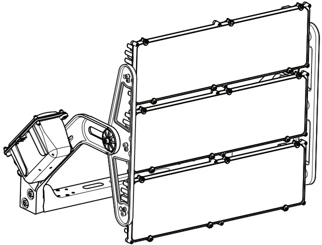
ALTIS G4 Floodlight
TYPE: ALG4 432L
IP66 / IK08![]() =30.9 kg
=30.9 kg![]() The luminaire with clear optic should be positioned so that prolonged staring into the luminaire at a distance <2m is not expected
The luminaire with clear optic should be positioned so that prolonged staring into the luminaire at a distance <2m is not expected![]() Caution, risk of electric shock
Caution, risk of electric shock
Extreme caution: Do not connect any LED CONNECTION wire (high voltage) inside NTC connector !! It could result in a critical failure and damage irreversibly the ALTIS luminaire
The light source contained in this luminaire shall only be replaced by the manufacturer or his service agent or a similar qualified person.![]()
GEAR BOX : ALG4 GB LE 432L
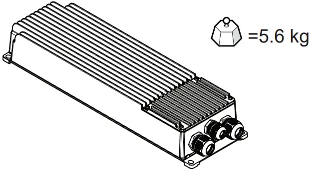
![]() TaMIN = -40°C / TaMAX = +50°C
TaMIN = -40°C / TaMAX = +50°C
(up to 50°C with driving current derating)
IP66 / IK08
corrosion environment from C1 to C3 according to standard ISO9223
ALG4 GB 432L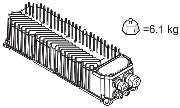 TaMIN = -40°C / TaMAX = +55°C
(up to 55°C with driving current derating)
IP66 / IK08
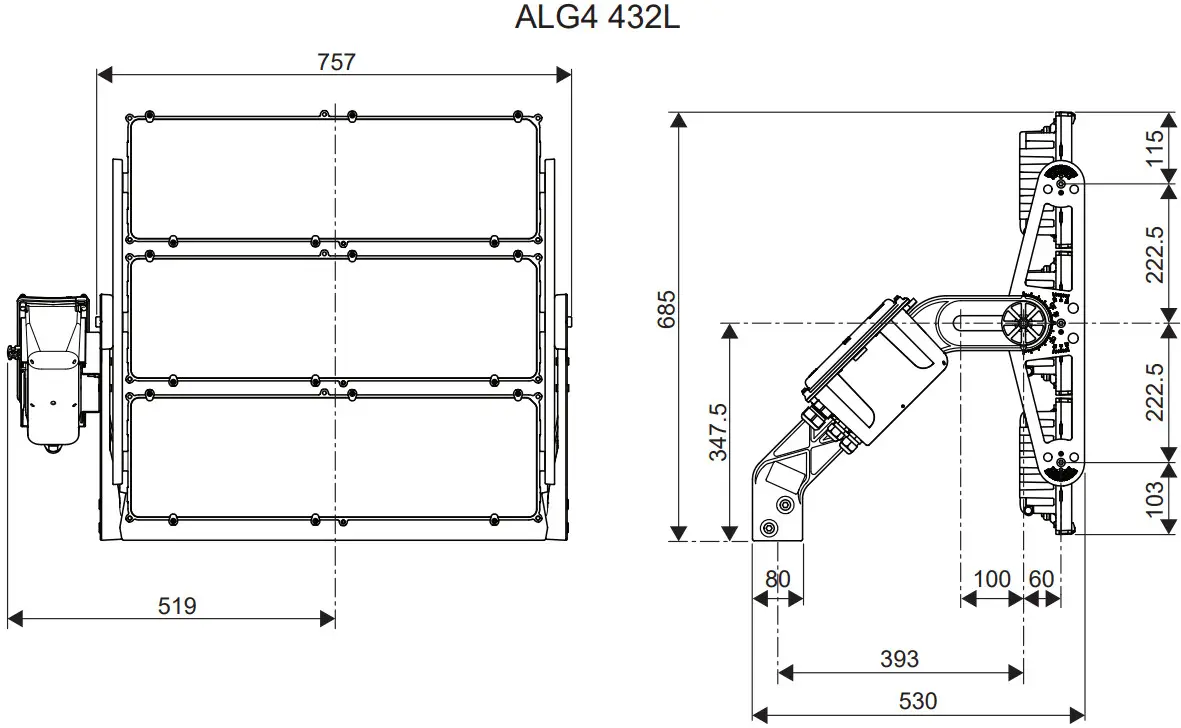
DIMENSIONS
| ScXO° * | ScX15′ * | ScX45° * | SX65′ * | ScX90° * | ||
| ALG4 | 432L | 0.14 | 0.26 | 0.48 | 0.55 | 0.57 |
 * These data refer to the worst case at indicated angle
ALG4 GB LE 432L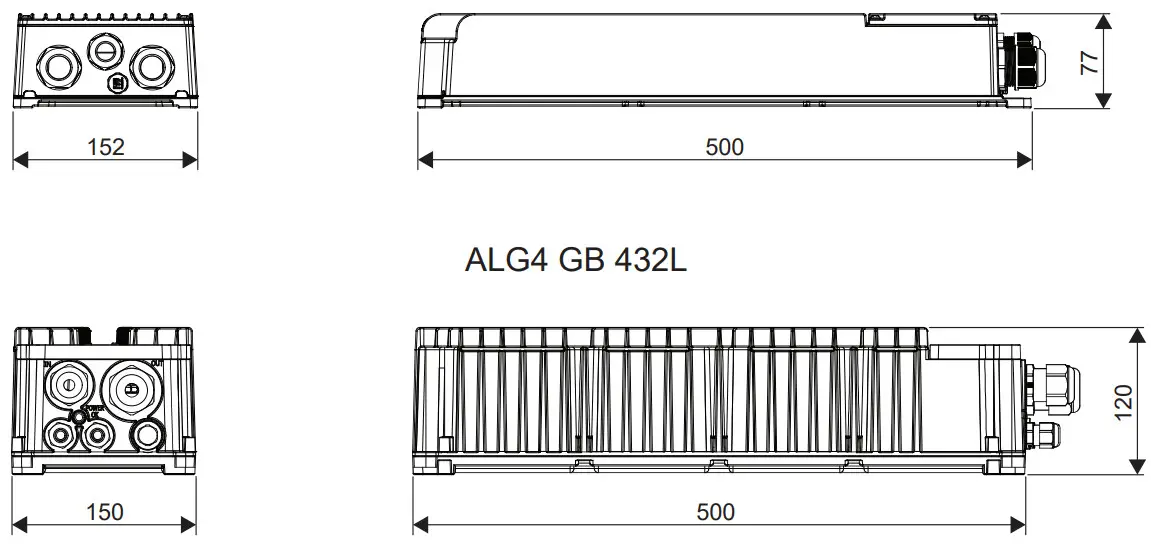
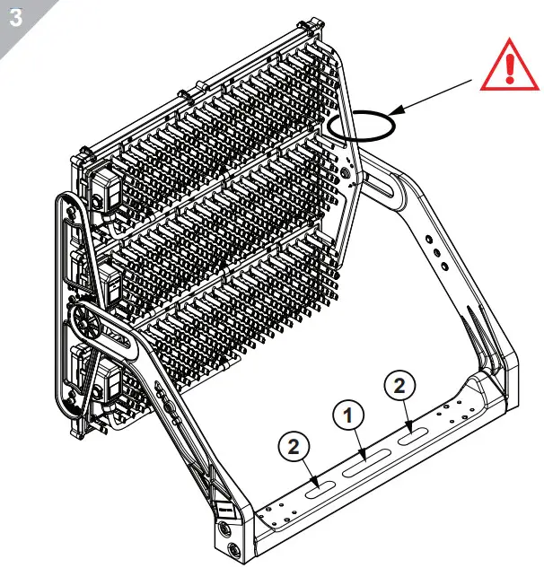
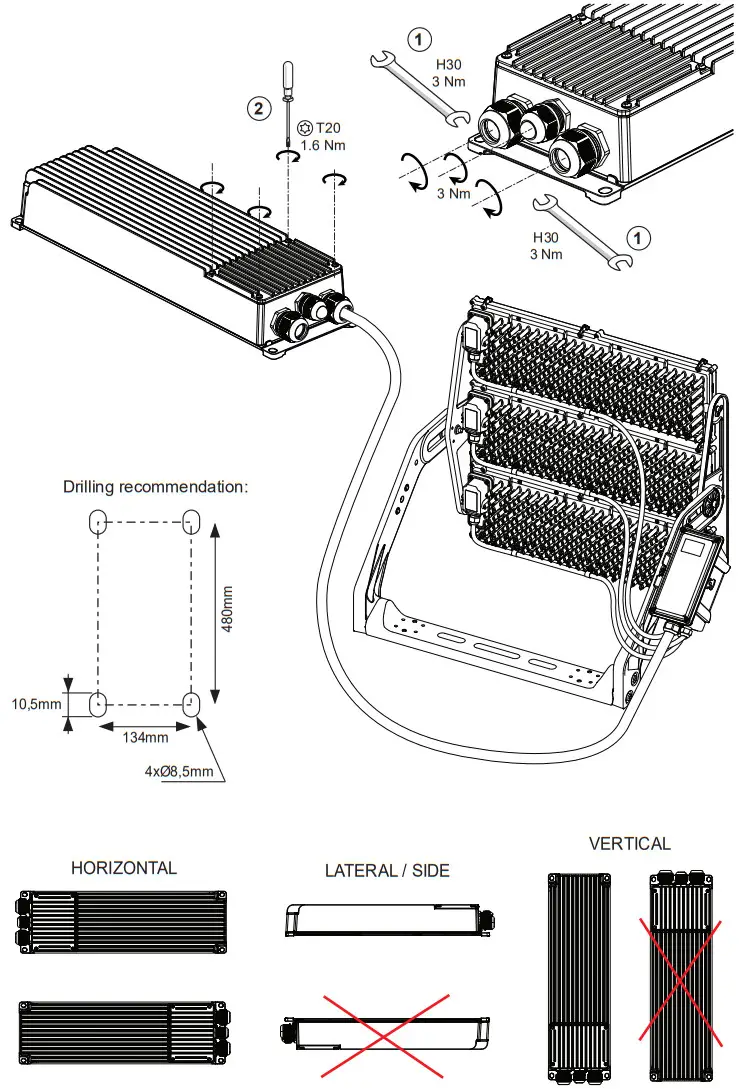
- 1xM20 with extra large washer (not provided)
or - 2xM20 with extra large washer (not provided)
For installation higher >3m
Secure product with retaining cable attached to the frame (not included in the delivery).
Please refer to local installation norms/regulations.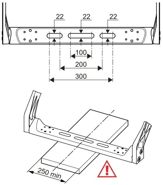
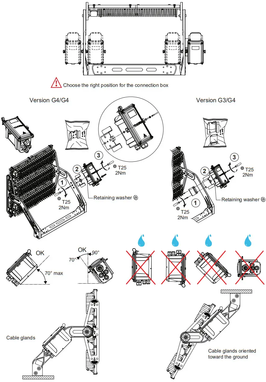
CONNECTION BOX
ELECTRICAL CONNECTION
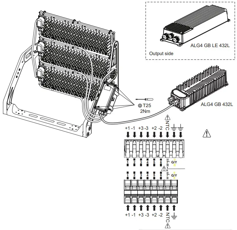 Extreme caution :
Do not connect any LED CONNECTION wire (high voltage) inside NTC connector !! It could result in a critical failure and damage irreversibly the ALTIS luminaire (7*) Optionnal : NTC connection (thermal monitoring).
Cable 9x cores or above is recommended (ex : H07 RN-F 9G1,5mm²)
| PINOUT | ||
| Number | Label | Description |
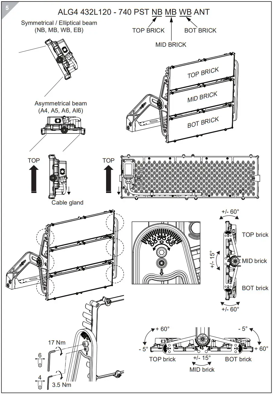
| 1 | +1 | LED1+Connection (TOP Brick |
| 2 | -1 | LED1-Connection (TOP Brick |
| 3 | +3 | LED3+Connection (BOT Brick |
| 4 | -3 | LED3-Connection (BOT Brick |
| 5 | +2 | LED2+Connection (MID Brick |
| 6 | -2 | LED2-Connection (MID Brick |
| 7 | NTC option | Thermal Measure INPUT |
| GND | PROTECTIVE EARTH | |
| GND | PROTECTIVE EARTH | |
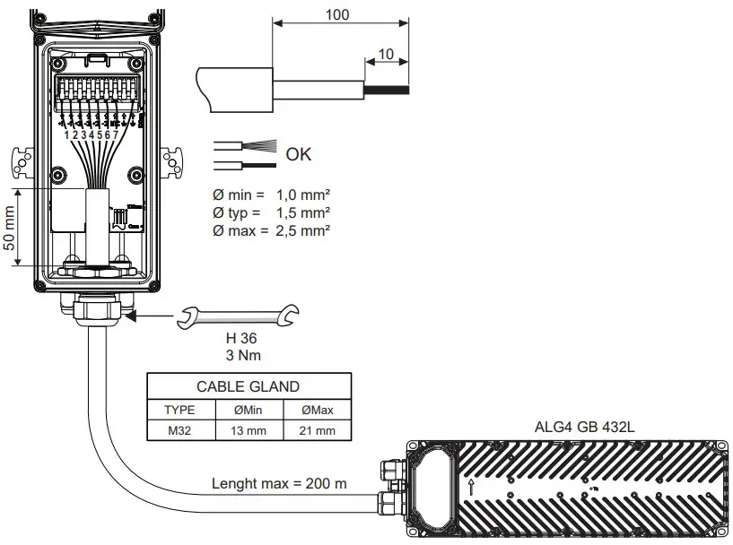 Recommended:
H07 RN-F 9G1,5 mm² with NTC connected or H07 RN-F 7G1,5 mm² if NTC not connected 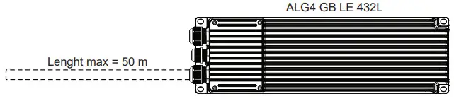 Recommended:
H07 RN-F 7G1,5 mm² ( Without NTC )
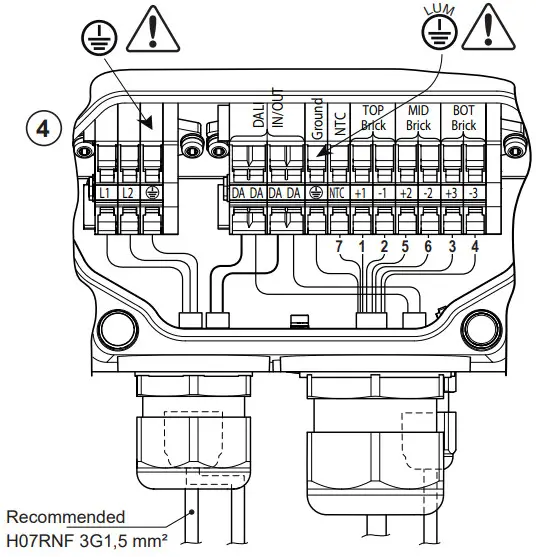
ALG4 GB 432L / ELECTRICAL CONNECTION / DALI
Extreme caution: Do not connect any LED CONNECTION wire (high voltage) inside NTC connector !! It could result in a critical failure and damage irreversibly the ALTIS luminaire
| PINOUT | ||
| Number | Label | Description |
| L1 | AC LINE 1 INPUT | |
| L2 | AC LINE 2 INPUT | |
| PROTECTIVE EARTH | ||
| DA+ | DALI INPUT | |
| DA+ | DALI RE-LAUNCH | |
| DA- | DALI INPUT | |
| DA- | DALI RE-LAUNCH | |
| PROTECTIVE EARTH FOR LED MODULE | ||
| 7 | NTC | THERMAL MEASURE INPUT |
| 1 | 1 | LED1+CONNECTION (TOP Brick) |
| 2 | -1 | LED1-CONNECTION (TOP Brick) |
| 5 | 2 | LED2+CONNECTION (MID Brick) |
| 6 | -2 | LED2-CONNECTION (MID Brick) |
| 3 | 3 | LED3+CONNECTION (BOT Brick) |
| 4 | -3 | LED3-CONNECTION (BOT Brick) |
| SIGNALLING LED INDICATIONS ON THE GEAR BOX | |||
| PERIOD | PULSES | FAULT DESCRIPTION | PRIORITY |
| The encoded faults are based on pulses emitted every 4 seconds | 1 | One or more CCR module enabled by config are not communicating with logic board | Maximum |
| 5 | Firmware version of one or more CCR module is not compatible with logic board firmware version | ||
| 2 | One or more CCR’s output is short-circuited | ||
| 3 | Load failure on one or more CCR’s output | ||
| 4 | Thermal derating active (output current reduction) | ||
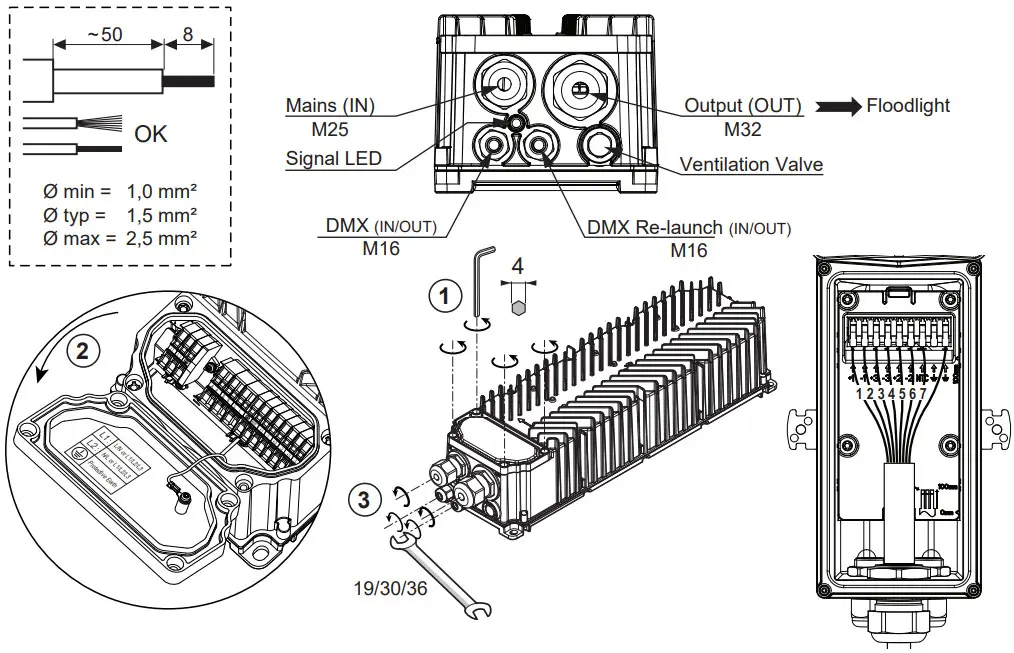
CABLE GLAND
| TYPE | ØMin | ØMax |
| M16 | 5 mm | 10 mm |
| M25 | 10 mm | 17 mm |
| M32 | 13 mm | 21 mm |
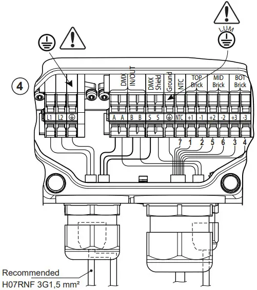
ALG4 GB 432L / ELECTRICAL CONNECTION / RDM-DMX
 Extreme caution: Do not connect any LED CONNECTION wire (high voltage) inside NTC connector !! It could result in a critical failure and damage irreversibly the ALTIS luminaire
| PINOUT | ||
| Number | Label | Description |
| L1 | AC LINE 1 INPUT | |
| L2 | AC LINE 2 INPUT | |
| PROTECTIVE EARTH | ||
| A | DMX INPUT DATA+ | |
| A | DMX-RE-LAUNCH DATA+ | |
| B | DMX INPUT DATA- | |
| B | DMX-RE-LAUNCH DATA | |
| S | DMX COMMON / SHIELD | |
| S | DMX COMMON / SHIELD | |
| PROTECTIVE EARTH FOR LED MODULE | ||
| 7 | NTC | THERMAL MEASURE INPUT |
| 1 | -1 | LED1+CONNECTION (TOP Brick) |
| 2 | 1 | LED1-CONNECTION (TOP Brick) |
| 5 | 2 | LED2+CONNECTION (MID Brick) |
| 6 | -2 | LED2-CONNECTION (MID Brick) |
| 3 | 3 | LED3+CONNECTION (BOT Brick) |
| 4 | -3 | LED3-CONNECTION (BOT Brick) |
| SIGNALLING LED INDICATIONS ON THE GEAR BOX | |||
| PERIOD | PULSES | FAULT DESCRIPTION | PRIORITY |
| The encoded faults are based on pulses emitted every 4 seconds | 1 | One or more CCR module enabled by config are not communicating with logic board | Maximum |
| 5 | Firmware version of one or more CCR module is not compatible with logic board firmware version | ||
| 2 | One or more CCR’s output is short-circuited | ||
| 3 | Load failure on one or more CCR’s output | ||
| 4 | Thermal derating active (output current reduction) | ||
CABLE GLAND
| TYPE | ØMin | ØMax |
| M16 | 5 mm | 10 mm |
| M25 | 10 mm | 17 mm |
| M32 | 13 mm | 21 mm |
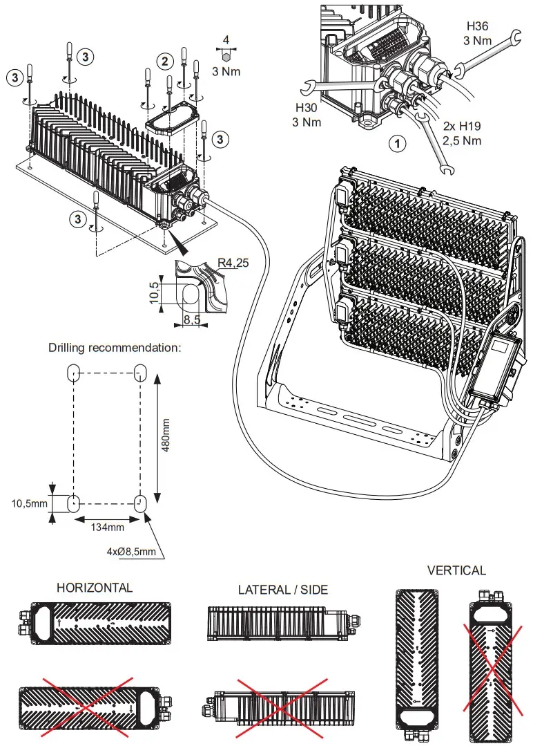
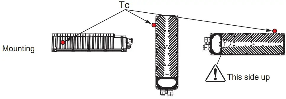
ALG4 GB 432L MOUNTING
ALG4 GB 432L / 200-250 Vac – ALG4 GB 432L/250-440 Vac
CIRCUIT BREAKER recommendation
It should mentioned in the notice that calculation has been done with a Circuit Breaker Load Factor of 100%.
| V in Nominal | Inrush Current Data | # Drivers for each Circuit Breaker | ||||||||||||
| I peak (A) | Half Value Time (ps) | Type B 10A | Type B 16A | Type B 20A | Type B 25A | Type C 10A | Type C 16A | Type C 20A | Type C 25A | Type D 10A | Type D 16A | Type D 20A | Type D 25A | |
| 230Vac | 40 | 2500 | 0 | 1 | 1 | 2 | 0 | 1 | 1 | 2 | 0 | 1 | 1 | 2 |
| 400Vac | 68 | 2000 | 0 | 1 | 1 | 1 | 1 | 1 | 2 | 2 | 1 | 1 | 2 | 3 |
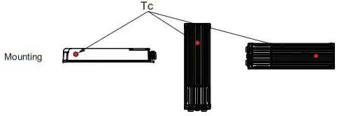
GUIDELINE FOR INTEGRATION OF GEAR BOX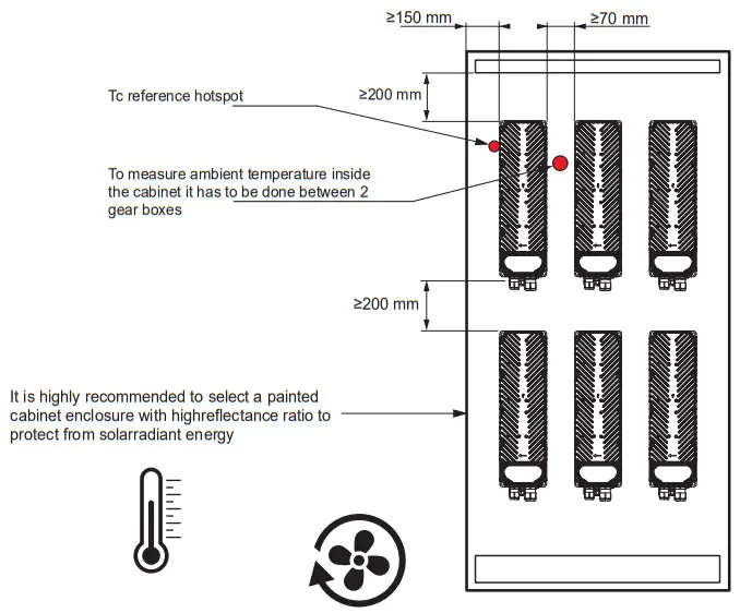 If you cannot follow instructions included in previous section regarding gear box integration, you have to measure Tc reference point taking into consideration that measures must be down to Tc_max
| Tc Reference at Max Ambient | |||
| Position | Horizontal | Vertical | Side |
 | |||
| 230Vac | 81°C | 80°C | 82°C (Ref.) |
| 400Vac | 69°C | 68°C | 70°C (Ref.) |
| Ambient Max | 55°C | 55°C | 55°C (Ref.) |
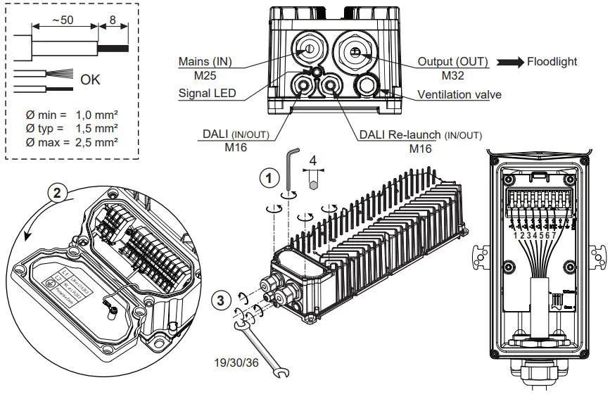
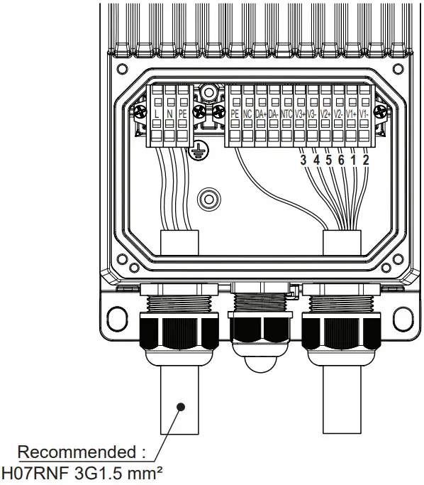
ALG4 GB LE 432L / ELECTRICAL CONNECTION
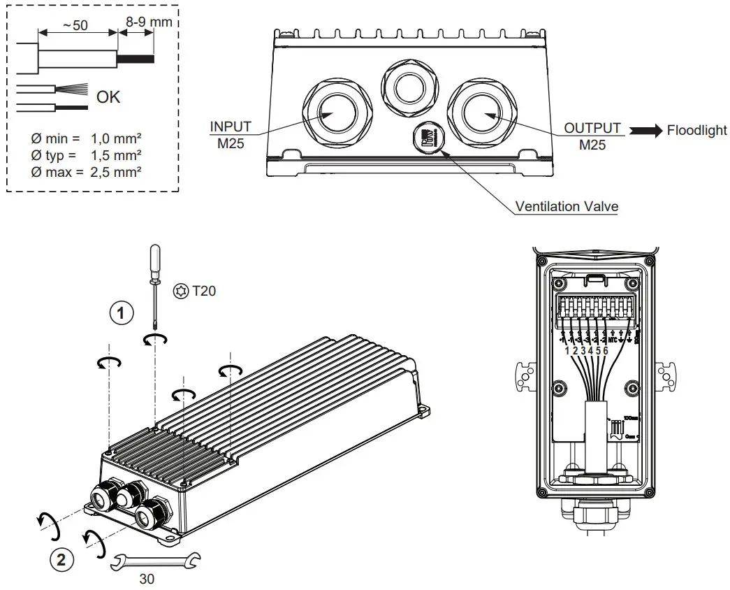
PINOUT
| Number | Label | Description |
| L | AC INPUT | |
| N | AC INPUT | |
| PE | PROTECTIVE EARTH | |
| PE | PE FOR LED MODULE | |
| NTC | THERMAL PROTECTION FOR LED FIXTURE | |
| 3 | V3+ | OUTPUT CHANNEL 3+ (BOT Brick) |
| 1 | V3- | OUTPUT CHANNEL 3- (BOT Brick) |
| 2 | V2+ | OUTPUT CHANNEL 2+ (MID Brick) |
| 4 | V2- | OUTPUT CHANNEL 2- (MID Brick) |
| 5 | V1+ | OUTPUT CHANNEL 1+ (TOP Brick) |
| 6 | V1- | OUTPUT CHANNEL 1- (TOP Brick) |
![]() The wiring should be strictly followed by the marking label instruction, Otherwise the product could be damaged or the fonctions could be affected.
The wiring should be strictly followed by the marking label instruction, Otherwise the product could be damaged or the fonctions could be affected.
Each set of + or – are not potential identical, cross connection is prohibited.
| CABLE GLAND | ||
| TYPE | ØMin | ØMax |
| M20 | 6.3 mm | 11.3 mm |
| M25 | 10 mm | 16.3 mm |
ALG4 GB LE 432L MOUNTING
ALG4 GB LE 432L / 200-250 Vac – ALG4 GB LE 432L/250-440 Vac
Drivers for each circuit breaker
Referring to the circuit breakers available on the market, the maximum number on the driver connectable for each circuit breaker is as the following table.
| Circuit Breaker Type | MCB B/C 10A | MCB B/C 16A | MCB B/C 20A | MCB B/C 25A | MCB B/C 32A |
| Input: 220~240Vac | 1 | 1 | 2 | 2 | 3 |
| Input: 380~400Vac | 1 | 2 | 2 | 3 | 4 |
GUIDELINE FOR INTEGRATION OF GEAR BOX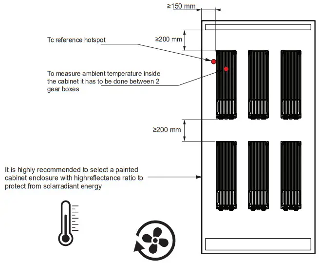 If you cannot follow instructions included in previous section regarding gear box integration, you have to measure Tc reference point taking into consideration that measures must be down to Tc_max
| Tc Reference at Max Ambient | |||
| Position | Horizontal | Vertical | Side |
 | |||
| 220Vac | 85°C | 84°C | 85°C (Ref.) |
| 400Vac | 80°C | 77°C | 80°C (Ref.) |
| Ambient Max | 50°C | 50°C | 50°C (Ref.) |
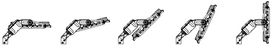
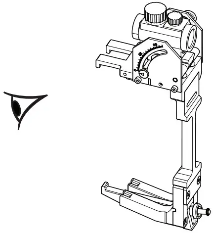
Aiming Device
ALTIS LED AIMING DEVICE
Installation instructions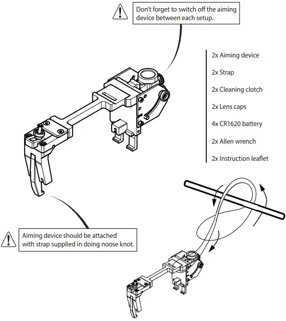
| 96671487 | ALTIS G5 AIMING DEVICE WITH VISOR |
| 96671488 | ALTIS G5 AIMING DEVICE BRACKET |
 Louvres / Bird Deterrent
ALTIS LED
Installation instructions
TYPE: ALTIS LED G4/G5 ACCESSORIES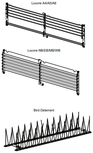
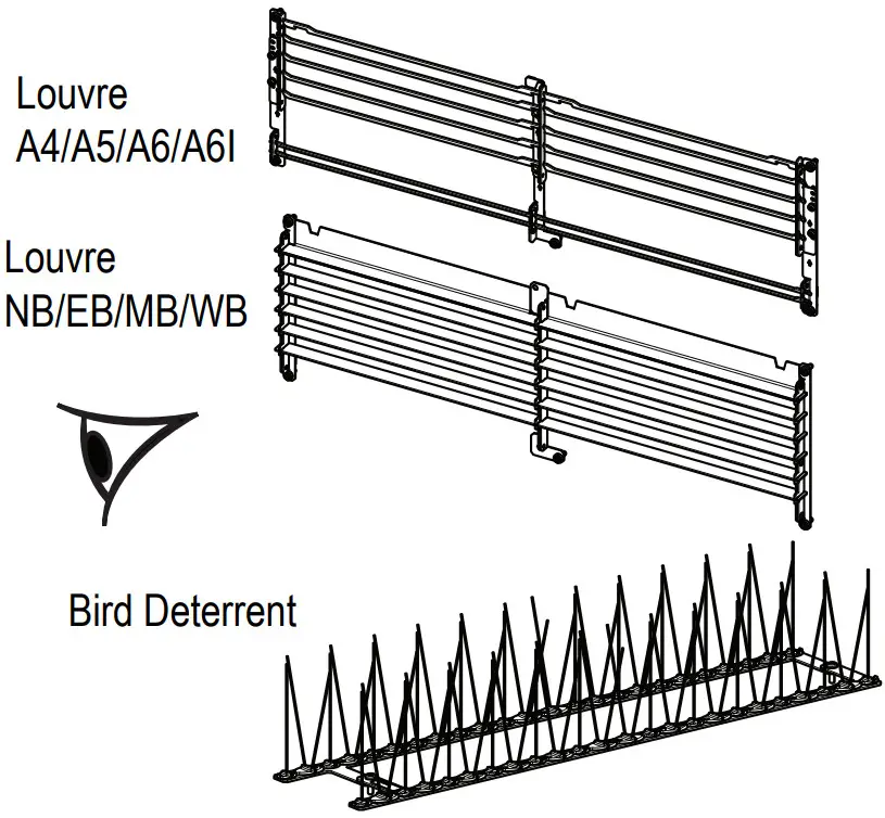
| 96671492 | ALTIS G5 1 BRICK LOUVRE A4 |
| 96671493 | ALTIS G5 1 BRICK LOUVRE A5 |
| 96671494 | ALTIS G5 1 BRICK LOUVRE A6/A6I |
| 96671496 | ALTIS G5 1 BRICK LOUVRE MB |
| 96671495 | ALTIS G5 1 BRICK LOUVRE NB/EB |
| 96671497 | ALTIS G5 1 BRICK LOUVRE WB |
96671489 ALTIS G5 BIRD DETERRENT
Visor
ALTIS LED
Installation instructions
TYPE: ALTIS G4/G5 ACCESSORIES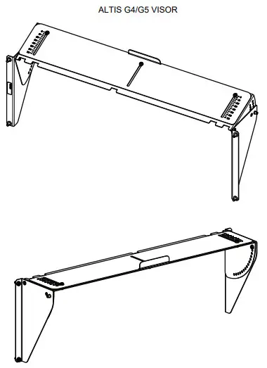 96671498 ALTIS G5 1 BRICK AJ VISOR
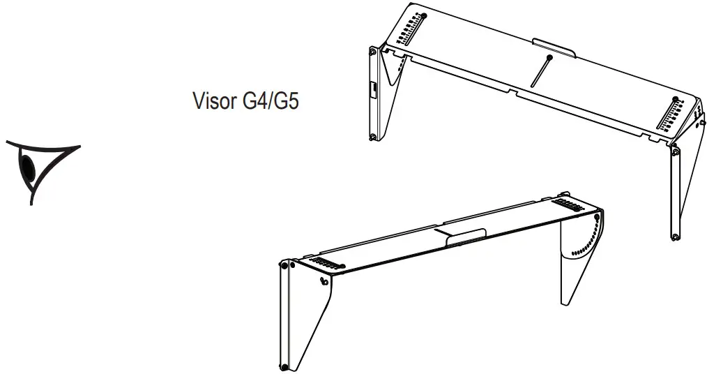 Power supply support
ALTIS LED
Installation instructions
TYPE: ALTIS G4/G5 ACCESSORIES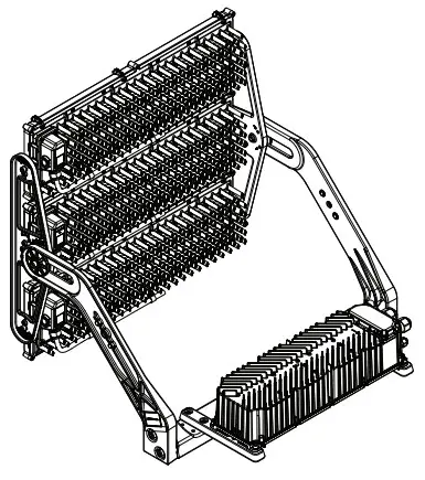 96671490 ALTIS G5 GB BRACKET 3 BRICK STIRRUP
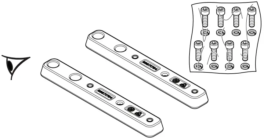
- Replace any cracked protective shield.
- Class II luminaires must be installed so that exposed metal work of the luminaire is not in contact with any part of the electrical installation connected to a protective conductor.
WARNING: Class I luminaires must be earthed. - This luminaire operates at mains voltage which must be switched off before intervention in control gear.
- Any modification to this luminaire is forbidden.
- Lighted objects nearer than the minimal distance in the is forbidden.
![]()
Thorn Lighting is constantly developing and improving its products. The right is reserved to change specifications without prior notification or public announcement.
© Thorn Lighting
 To ensure maintaining the best system performances, we advice to switch on the system “At least one night hour per month”.
- corrosion environment from C1 to C5 according to standard ISO9223 except gear box ALG4 GB LE 432L corrosion environment from C1 to C3


